CN111422759A - Method for dismantling tower crane in narrow space - Google Patents
Method for dismantling tower crane in narrow space Download PDFInfo
- Publication number
- CN111422759A CN111422759A CN202010303646.2A CN202010303646A CN111422759A CN 111422759 A CN111422759 A CN 111422759A CN 202010303646 A CN202010303646 A CN 202010303646A CN 111422759 A CN111422759 A CN 111422759A
- Authority
- CN
- China
- Prior art keywords
- tower crane
- dismantling
- arm
- boom
- small
- Prior art date
- Legal status (The legal status is an assumption and is not a legal conclusion. Google has not performed a legal analysis and makes no representation as to the accuracy of the status listed.)
- Granted
Links
- 238000000034 method Methods 0.000 title claims abstract description 25
- 238000009434 installation Methods 0.000 claims abstract description 6
- 238000007599 discharging Methods 0.000 claims abstract description 5
- 230000007246 mechanism Effects 0.000 claims description 49
- 229910000831 Steel Inorganic materials 0.000 claims description 25
- 239000010959 steel Substances 0.000 claims description 25
- 230000003014 reinforcing effect Effects 0.000 claims description 6
- 238000002360 preparation method Methods 0.000 claims description 4
- 230000000149 penetrating effect Effects 0.000 claims description 2
- 238000010276 construction Methods 0.000 abstract description 8
- 238000010586 diagram Methods 0.000 description 6
- 230000002787 reinforcement Effects 0.000 description 6
- 230000003247 decreasing effect Effects 0.000 description 3
- 238000012986 modification Methods 0.000 description 2
- 230000004048 modification Effects 0.000 description 2
- 229910001294 Reinforcing steel Inorganic materials 0.000 description 1
- 230000006978 adaptation Effects 0.000 description 1
- 230000009286 beneficial effect Effects 0.000 description 1
- 238000009435 building construction Methods 0.000 description 1
- 238000012790 confirmation Methods 0.000 description 1
- 238000001816 cooling Methods 0.000 description 1
- 238000000354 decomposition reaction Methods 0.000 description 1
- 210000003414 extremity Anatomy 0.000 description 1
- 210000000245 forearm Anatomy 0.000 description 1
- 230000005484 gravity Effects 0.000 description 1
- 239000002994 raw material Substances 0.000 description 1
- 238000004804 winding Methods 0.000 description 1
- 239000002023 wood Substances 0.000 description 1
Images




Classifications
-
- B—PERFORMING OPERATIONS; TRANSPORTING
- B66—HOISTING; LIFTING; HAULING
- B66C—CRANES; LOAD-ENGAGING ELEMENTS OR DEVICES FOR CRANES, CAPSTANS, WINCHES, OR TACKLES
- B66C23/00—Cranes comprising essentially a beam, boom, or triangular structure acting as a cantilever and mounted for translatory of swinging movements in vertical or horizontal planes or a combination of such movements, e.g. jib-cranes, derricks, tower cranes
- B66C23/18—Cranes comprising essentially a beam, boom, or triangular structure acting as a cantilever and mounted for translatory of swinging movements in vertical or horizontal planes or a combination of such movements, e.g. jib-cranes, derricks, tower cranes specially adapted for use in particular purposes
- B66C23/26—Cranes comprising essentially a beam, boom, or triangular structure acting as a cantilever and mounted for translatory of swinging movements in vertical or horizontal planes or a combination of such movements, e.g. jib-cranes, derricks, tower cranes specially adapted for use in particular purposes for use on building sites; constructed, e.g. with separable parts, to facilitate rapid assembly or dismantling, for operation at successively higher levels, for transport by road or rail
-
- B—PERFORMING OPERATIONS; TRANSPORTING
- B66—HOISTING; LIFTING; HAULING
- B66C—CRANES; LOAD-ENGAGING ELEMENTS OR DEVICES FOR CRANES, CAPSTANS, WINCHES, OR TACKLES
- B66C23/00—Cranes comprising essentially a beam, boom, or triangular structure acting as a cantilever and mounted for translatory of swinging movements in vertical or horizontal planes or a combination of such movements, e.g. jib-cranes, derricks, tower cranes
- B66C23/62—Constructional features or details
-
- B—PERFORMING OPERATIONS; TRANSPORTING
- B66—HOISTING; LIFTING; HAULING
- B66C—CRANES; LOAD-ENGAGING ELEMENTS OR DEVICES FOR CRANES, CAPSTANS, WINCHES, OR TACKLES
- B66C2700/00—Cranes
- B66C2700/03—Cranes with arms or jibs; Multiple cranes
Landscapes
- Engineering & Computer Science (AREA)
- Mechanical Engineering (AREA)
- Structural Engineering (AREA)
- Transportation (AREA)
- Working Measures On Existing Buildindgs (AREA)
- Jib Cranes (AREA)
Abstract
The invention discloses a method for dismantling a tower crane in a narrow space, wherein the tower crane comprises a large tower crane and a small tower crane, the installation height of the small tower crane is lower than that of the large tower crane, the turning radius of a boom rod of the small tower is smaller than the distance between the two tower cranes, and the dismantling step comprises the following steps: step one, increasing the length of an arm lever on the basis of the basic length of a small tower crane; step two, the height of the small tower crane is increased, the height of the large tower crane is reduced, and the arm rod of the large tower crane is detached by using the small tower crane; step three, self-descending dismantling of the large tower crane body; step four, reducing the height of the small tower crane and self-discharging the balance weight; fifthly, utilizing a self-disassembling device to disassemble the small tower boom rods section by section in the air to a basic length; step six, the small tower crane body is connected with an arm rod with a basic length and is detached in a self-descending manner; and seventhly, disassembling the boom rod with the basic length of the small tower crane on the ground. The method can realize the dismantling of the large tower crane in the narrow space, and has the advantages of low construction difficulty, easy control and high safety.
Description
Technical Field
The invention relates to the technical field of building construction, in particular to a method for dismantling a tower crane in a narrow space.
Background
The tower crane, also called "tower crane", is the most common hoisting equipment in construction sites, and is used to hang construction raw materials such as reinforcing steel bars, wood ridges, concrete, steel pipes and the like for construction by lengthening (height) one section by one section (called "standard section" for short). After the tower crane is operated, the traditional dismantling mode is that the standard section of the tower body is dismantled through a self-lifting mechanism of the tower body, and the arm rod is dismantled after falling to the ground. However, in many construction projects, the tower crane is in a narrow space, for example, the tower crane arranged in an indirect cooling tower, and the arm rod cannot fall down by adopting the traditional dismantling mode. For this reason, we need to design a new dismantling scheme.
Disclosure of Invention
The invention aims to provide a method for dismantling a tower crane in a narrow space, which solves the problem that the traditional method for dismantling the tower crane cannot be carried out in the narrow space.
The invention realizes the purpose through the following technical scheme:
a method for dismantling a tower crane in a narrow space comprises the steps that the tower crane comprises a large tower crane and a small tower crane, the installation height of the small tower crane is lower than that of the large tower crane, the turning radius of a boom rod of the small tower is smaller than the distance between the two tower cranes, and the dismantling step comprises
Step one, increasing the length of an arm lever on the basis of the basic length of a small tower crane;
step two, the height of the small tower crane is increased, the height of the large tower crane is reduced, and the arm rod of the large tower crane is detached by using the small tower crane;
step three, self-descending dismantling of the large tower crane body;
step four, reducing the height of the small tower crane and self-discharging the balance weight;
fifthly, utilizing a self-disassembling device to disassemble the small tower boom rods section by section in the air to a basic length;
step six, the small tower crane body is connected with an arm rod with a basic length and is detached in a self-descending manner;
and seventhly, disassembling the boom rod with the basic length of the small tower crane on the ground.
The further improvement is that in the step one, when the length of the arm rod is increased, the counter weight, the standard arm and the length pull rod of the corresponding small tower crane are calculated and synchronously increased.
The method is further improved in that the specific operation of the first step comprises the steps of detaching an original balance weight of a small tower crane by using a large tower crane through ①, detaching a lifting hook of the small tower crane through ②, retracting an amplitude variation trolley to the root of a large arm and detaching an amplitude variation rope, enabling the large arms of the two tower cranes to coincide with each other, lowering ③ an original large arm section of the small tower crane to the ground by using the large tower crane, assembling a standard arm support and a long pull rod of the small tower crane to be additionally provided with a cargo boom on the ground through ④, lifting the standard arm support and the long pull rod by using the large tower crane and connecting the standard arm support and the long pull rod with the residual arm section of the small tower crane, completing the installation of the long pull rod by using the large tower crane through ⑤, installing the balance weight of the small tower crane by using the large tower crane, penetrating an amplitude variation.
The further improvement is that the specific operation of using the small tower crane to dismantle the boom rod of the large tower crane comprises ① using the small tower crane to dismantle the balance weight of the large tower crane and reserve a balance weight, ② dismantling the lifting hook and the amplitude rope of the large tower crane, ③ using the small tower crane to dismantle the long pull rod arm section, the lifting arm section, the short pull rod arm section and the short pull rod of the large tower crane one by one and lower the same to the ground, ④ using the small tower crane to dismantle the last balance weight of the large tower crane, ⑤ using the small tower crane to dismantle the rear arm section and the pull rod of the balance arm of the large tower crane, and ⑥ using the small tower crane to dismantle the front arm section of the balance arm of.
The further improvement is that when the long pull rod arm section of the large tower crane is disassembled, the middle section position of the arm section of the large tower crane is pulled by using a small tower crane, the large arm of the large tower crane is fixed on the tower body of the small tower crane by using a steel wire rope and a snap ring, then the long pull rod and the short pull rod are put down to the upper chord of the cargo boom by using a lifting rope of the large tower crane, and the arm sections of the long pull rod of the large tower crane are disassembled one by using the small;
when the boom arm section is disassembled, the lifting rope of the small tower crane is started, the short pull rod of the large tower crane is pulled to the tower top, and after the pin shaft is installed, the steel wire rope and the snap ring are loosened, and the boom arm section of the large tower crane is disassembled.
The further improvement is that if the large tower crane is provided with the attachment rod, the attachment rod is detached after the large tower crane body is detached by self-descending.
In a further improvement, the specific operation of detaching the attachment bar comprises:
when dismantling the reinforcing ring and adhering to pole and otic placode support, direct manual work is dismantled on the reinforcing ring:
when the non-reinforcing ring is detached to be attached, two winches are arranged on the ground, fixed pulleys are arranged above two ends of the attachment rod respectively and used as guides, the attachment rod is hoisted after the two winch steel wire ropes penetrate the fixed pulleys respectively, the attachment rod is slowly lowered by the two winches after the pin shafts at two ends of the attachment rod are detached, and finally the lowest attachment and residual parts on the ground are detached by adopting a truck crane and scattered.
The self-disassembling device is further improved in that the self-disassembling device comprises a lifting mechanism, a rod handling mechanism, an anti-disengaging mechanism and a hoist mechanism;
the concrete operation of the fifth step comprises ① preparation work before disassembly, ② transportation of a rod mechanism to the front end of a non-disassembled arm section by using a luffing trolley, parking, binding a lifting rope of a lifting mechanism on the arm section to be disassembled, inching, disassembling a lower chord pin shaft, installing an anti-disengaging mechanism, sliding and slightly pre-tightening a lower chord of the arm section to be disassembled by using two hoist mechanisms, disassembling an upper chord pin shaft, continuously sliding hoist mechanisms on two sides, releasing the lifting rope until the lifting rope is not stressed, disassembling the lifting rope and fixing the lifting rope at the node position of the boom section to be disassembled, adjusting the hoist mechanisms and the lifting rope, disassembling the pin shaft of the anti-disengaging mechanism after ensuring that the arm section to be disassembled is stable, separating the arm section to be disassembled from the non-disassembled arm section, starting the lifting mechanism to lower the arm section to be disassembled, and sequentially disassembling a plurality of arm sections in the middle section by using the method in ③ and ② and leaving the two arm sections.
The further improvement is that the preparation work before disassembly comprises ① retracting the luffing trolley to the root of the boom, disassembling the lifting steel wire rope, placing the lifting hook on the introduction beam, ② drawing two steel wire ropes from the lower chords at the two sides of the front end of the middle section boom section to the top of the tower to be fixed, slightly pre-tightening the two steel wire ropes by using two hoists respectively, slightly lifting the boom to be lifted, ③ disassembling the lifting hook, recovering the steel wire rope of the trolley after the main hoisting pulley of the tensioning pull rod is wound, disassembling the balance weight, disassembling the long pull rod and a connecting pin shaft of a pull plate at the top of the tower, placing the long pull rod into a slot of the boom by using a hoist chain block, ④ disassembling the long pull rod into the shortest single section, and firmly binding each section of the pull rod on the inclined.
The further improvement is that the concrete operation of the step six comprises ① balancing before tower descending, ② normal tower descending operation after balancing, and ③ detaching the attaching rod operation.
The invention has the beneficial effects that: the method can realize the dismantling of the large tower crane in the narrow space, and has the advantages of low construction difficulty, easy control and high safety.
Drawings
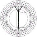
FIG. 1 is a layout diagram of two tower cranes in a cold room tower in the embodiment;
FIGS. 2 to 6 are different operation diagrams in the first step of the embodiment;
FIGS. 7 to 13 are schematic diagrams illustrating different operations in step two according to the embodiment;
FIGS. 14 and 15 are schematic diagrams illustrating different operations in step three of the embodiment;
FIGS. 16 to 22 are schematic diagrams illustrating different operations in step five according to the embodiment;
FIG. 23 is a schematic diagram showing the operation in step six of the embodiment;
in the figure: 1. a reinforcement ring; 2. an attachment rod; 3. a winch; 4. a fixed pulley; 5. a lever mechanism; 6. hoisting a rope; 7. an anti-drop mechanism; 8. a hoist mechanism.
Detailed Description
The present application will now be described in further detail with reference to the drawings, it should be noted that the following detailed description is given for illustrative purposes only and is not to be construed as limiting the scope of the present application, as those skilled in the art will be able to make numerous insubstantial modifications and adaptations to the present application based on the above disclosure.
Example (b): the disassembly of a tower crane A (small tower crane) and a tower crane B (large tower crane) arranged in a certain project cold room tower is shown in the figure 1.
Step one, increasing the length of an arm lever on the basis of the basic length of a small tower crane
The on-site situation is that the height of the tower crane A is 176.25m (47 knots), the height of the tower crane B is 190.4m (32 knots), the cargo boom of the tower crane A needs to be lengthened to 55m (the length of the original cargo boom is 47.5m), the cargo boom of the tower crane A needs to be increased to 55m, and 13 t counter weight, one 10m standard arm 3 and two 4915mm length pull rods need to be synchronously increased through calculation. The specific operation is as follows:
① As shown in FIG. 2, the brake system of the hoisting mechanism of the tower crane B and the operation of each mechanism are checked to be normal, after the confirmation that the construction requirements are met, the tower crane B is used for disassembling the counterweight of the tower crane A (a 4t counterweight is reserved), the counterweight of the tower crane A is the heaviest 4t, and the tower crane B meets the disassembly requirements.
② As shown in figure 3, the lifting hook of tower crane A is disassembled, the amplitude variation trolley is retracted to the root of the big arm and the amplitude variation rope is removed, and the two big arms of tower crane are overlapped.
③ the original large arm section of the small tower crane is lowered to the ground by using a large tower crane, as shown in fig. 4, a tower crane B is used for hanging 27.5m arm sections (the gravity center reference position is 32m, the weight is 7.5t) at the back part of a short pull rod of a tower crane boom A, then a hoisting rope is used for pulling a long pull rod headstock and detaching a pin shaft, the long pull rod is slowly lowered to an upper chord of the boom, a 12mm diameter steel wire rope with the diameter of 12m is fixed on the upper chord (the operation radius is 36m) of the tower crane boom B, an upper chord of the large arm of the tower crane A is lowered, a chain block with the chain of 2t and 6m is hung, then as shown in fig. 5, pin shafts at two ends of a long pull rod section III are detached and fixed on a large arm diagonal web member, the rope is retracted and the chain block, the short rail and the tower crane boom are lifted to the tower top by using the hoisting rope, the pin shaft is fixed, the hoisting rope is loosened, after a connecting pin shaft of the large arm section II of the tower crane boom section and the arm section II of the tower crane A are detached, the large.
④ As shown in FIG. 6, a 35m standard jib of A tower crane jib and a residual long pull rod (reserved pull rod section IV is not installed, length is 6.3m) are assembled on the ground, B tower crane jib 35m standard jib and residual long pull rod are connected with A tower crane jib section II, after pin shaft is penetrated, short pull rod is put into jib by A tower crane lifting rope, A tower crane is started to rotate, 55m jib is slowly rotated to be close to B tower crane standard section, 5m long diameter 32mm steel wire rope and 1 24t snap ring are adopted, upper chord of A tower crane large jib section VI is connected and fixed with B tower crane tower body standard section main limb, B tower crane slowly unloads hook, and hand chain block tooling replacing the 2t hoisting weight and 6m chain completes the installation of A tower crane long pull rod of A55 m standard jib, thus, 55m jib installation is completed.
⑤ the tower B machine is used to install the counterweight of tower A machine, the amplitude-variable steel cable is passed through, the lifting hook is installed, and the whole machine is debugged.
⑥ two tools for hoisting the A-type tower crane by the B-type tower crane, namely a counterweight self-unloading frame and a boom self-unloading handle rod (parts are assembled and placed on a balance arm to be fixed).
Step two, the height of the small tower crane is increased, the height of the large tower crane is reduced, and the arm rod of the large tower crane is dismantled by using the small tower crane
The method comprises the following specific operations of firstly descending the tower crane B by three standard joints, then jacking the tower crane A by three standard joints, and dismantling the arm lever of the tower crane B by the tower crane A:
① As shown in FIG. 7, the brake system of the hoisting mechanism of the tower crane A and the operation of each mechanism are checked to be normal, after the construction requirements are confirmed to be met, the balance weight of the tower crane B is disassembled by the tower crane A (a balance weight of 5t is reserved), the balance weight of the tower crane B is 5t, the operation radius is 33m when the tower crane A is disassembled, the rated hoisting weight is 8t, and the disassembly is met.
② disassembling the hook and the luffing rope of the tower crane B.
③ As shown in FIG. 8, the tower crane A is used to hold the middle section of the tower crane B's 5 th section arm, the tower crane B's large arm is fixed on the tower crane A's body by the illustrated steel wire rope and the illustrated snap ring, then the tower crane B is used to lift the rope to lower the long and short pull rods to the boom upper chord, the tower crane A is used to disassemble the arm section VI of the tower crane B's long pull rod one by one to arm section X and then to the ground, as shown in FIG. 9, the lifting rope is started to pull the tower crane B's short pull rod to the tower top, and the pin shaft is installed, the steel wire rope and the snap ring are loosened to disassemble the tower crane B's boom arm sections IV, 5, 6, 7, 9, totaling to 31.2m, 5.59t in weight, 10m in operating radius of the tower crane A, and 8t in rated lifting weight to meet the disassembling requirement, as shown in FIG. 10, the arm section III before the tower crane B's short pull rod is disassembled, 2.11t in weight, 29m in operating radius of the tower crane A, and 8t in rated lifting weight to meet the disassembling requirement.
④ disassembling the last 5t counterweight, drawing out the steel wire rope of the hoisting mechanism to place 3.15t on the ground, and independently lowering the rest 4.76t, wherein the operation radius of the tower crane A is 45m, and the rated hoisting weight is 7.22t, thereby meeting the disassembly requirement.
⑤ the total 4.3t of the rear arm section of the balance arm and the two pull rods of the balance arm are disassembled, the operation radius of the tower crane A is 35m, the rated hoisting weight is 8t, and the disassembly requirement is met, the concrete steps are that the tower crane A hoists the rear half arm hoisting point, the pull rod pin shaft is broken, the steel wire rope and the hand hoist are pulled and connected as shown in figure 12;
⑥ As shown in FIG. 13, the balance arm forearm knuckle weight is disassembled by 3.42t, the A tower crane operation radius is 45m, the rated hanging weight is 7.22t according to the method, and the disassembly requirement is satisfied.
Step three, self-descending dismantling of the tower body of the large tower crane
As shown in fig. 14, before lowering the tower, the deck on the opposite side of the jacking cylinder must be removed to avoid mechanical interference with the structural reinforcement ring; when the standard knot is lowered, the standard knot is pushed out to the outermost end of the introducing beam and then lowered by the tower crane A, the operation radius is 50m, the rated hanging weight is 6.38t, and the weight of a single standard knot is 5.752t, so that the lowering requirement is met.
In addition, in this embodiment, the B tower attachment bar needs to be removed. As shown in fig. 15, when detaching the attachment rod 2 and the ear plate support of the reinforcement ring 1, the attachment rod 2 and the ear plate support are directly detached manually on the reinforcement ring 1, when detaching the non-reinforcement ring, two winches 3 are required to be arranged on the ground, a fixed pulley 4 is respectively arranged above two ends of the attachment rod as a guide (can be hooped on the structure of the reinforcement ring 1), the attachment rod 2 is hoisted after two winch steel wire ropes respectively pass through the fixed pulleys 4, and after detaching the pin shafts at two ends of the attachment rod 2, the attachment rod 2 is slowly lowered by the two winches 3 at the same time; and finally, removing the lowest attached part and the rest parts of the tower crane B by using the truck crane ground and scattering the parts.
Step four, reducing the height of the small tower crane and self-discharging the balance weight
Firstly, the tower crane A automatically lowers 4 standard sections, then the counterweight is lowered by utilizing the installed counterweight self-discharging device, and only two 4t counterweight blocks are reserved.
Fifthly, utilizing a self-disassembling device to disassemble the small tower boom rod section by section to the basic length
The self-disassembling device comprises a lifting mechanism, a handle mechanism, an anti-falling mechanism and a hoist mechanism, wherein the handle mechanism is arranged at the front end of an upper chord of a non-disassembling arm section; the anti-falling mechanism is connected between the arm section to be disassembled and the lower chord of the non-disassembled arm section and is used for providing a rotating connection point for the arm section to be disassembled; the lifting mechanism is formed by connecting a winch and a lifting rope, and the lifting rope is bound to the arm section to be disassembled after bypassing the handle bar mechanism and is used for lowering the arm section to be disassembled; the hoist mechanism is hung on the upper chord of the non-disassembled arm section, and the hook of the hoist mechanism hooks the arm section to be disassembled. The concrete operation of the step five is as follows:
① after the trolley is retracted to the root of the big arm, the hoisting wire rope is disassembled, the hook is placed on the leading-in beam, and the arm section is reinstalled after the last 20 m.
② As shown in figure 16, two 20mm diameter double steel wire ropes are tied from the lower chords at the two sides of the front end of the arm section IV to the top of the tower to be fixed, and are slightly pre-tightened by two 5t hoists respectively, and the large arm is slightly lifted to be raised.
③ detaching the hook, recovering the steel cable of the trolley after the main winding pulley of the tension rod is wound, detaching the balance weight, detaching the long rod and the connecting pin shaft of the tower top pulling plate, and putting the long rod into the big arm slot by the hoist chain block, as shown in fig. 17.
④ the long pull rod is broken down into the shortest single segment, and each segment is tied on the big arm diagonal web member by small diameter wire rope.
⑤ A, using a trolley to transport a lever mechanism 5 to the front end of an arm section V (arm section to be disassembled), stopping the trolley, binding a lifting rope 6 at a position 4m away from the tail end of the arm section VI, inching, disassembling a lower chord pin shaft, installing an anti-falling mechanism 7, as shown in figure 19, using two 1T hoist mechanisms 8 to slide down the lower chord of the arm section VI and slightly pre-tighten the lower chord and disassemble an upper chord pin shaft, as shown in figures 21 and 22, continuing to slide down the 1T hoist mechanisms 8 at two sides, releasing the lifting rope 6 until the lifting rope 6 is not stressed, disassembling the lifting rope 6 to the position shown in figure 21 and fixing the lifting rope 6 at the chord node position of the arm section VI, adjusting the hoist and the lifting rope 6, disassembling the anti-falling mechanism 7 pin shaft after ensuring the arm section is stable, separating the arm section VI from the arm section V, and starting the lifting mechanism to lower the arm section VI.
⑥, disassembling a 10m long arm section V with the weight of 1.23t, a 5m long arm section IV with the weight of 0.7t and a 10m long arm section III with the weight of 1.33t by using the method in ⑤, wherein the total length of the arm section III and the arm section IV is 15m and the weight of 2.03, the pin shaft is disassembled after the lifting rope is directly pre-tightened by a tower tip at one time, and the tool is installed at the front end of the arm section II during the downward operation.
Step six, the small tower crane body is connected with the arm lever with the basic length to be automatically descended and dismantled
And the front end of the arm section II is provided with a trolley walking limit and an arm section X, a lifting rope is wound again, a lifting hook is arranged, and the arm sections I and II are utilized for normal tower descending operation.
① pre-tower balancing, known boom decreasing moment 13.3 x 23.4-7.3 x 10-2.2 x 22.1-160, balance arm increasing moment 17m x, balance arm decreasing moment 18 x 17-306, front and rear arm decreasing moment equal 160+17 x-306;
therefore, x is 8.59t, that is, two 4t balance weights must be reserved in the early stage and are not detached for balancing.
② and carrying out normal tower descending operation after balancing.
③ the operation of detaching the attachment bar is similar to the operation of detaching the attachment bar of a B tower crane described above, i.e. detaching it at the ground using a winch (as shown in FIG. 23).
Seventhly, disassembling and removing the basic length arm rod of the small tower crane on the ground
And (4) after the tower crane A is attached to the lowest tower crane, carrying out ground disassembly by a truck crane, wherein the conventional tower descending operation is carried out, and the step decomposition description is not carried out.
And at this moment, the two tower cranes are completely lowered to the lowest level and are completely disassembled by the truck crane, and the disassembling operation is completed.
The above-mentioned embodiments only express several embodiments of the present invention, and the description thereof is more specific and detailed, but not construed as limiting the scope of the present invention. It should be noted that, for a person skilled in the art, several variations and modifications can be made without departing from the inventive concept, which falls within the scope of the present invention.
Claims (10)
1. The utility model provides a method that tower crane demolishd in narrow space, the tower crane includes a big tower crane and a little tower crane, little tower crane mounting height is less than big tower crane, and little tower davit pole radius of gyration is less than the interval of two tower cranes, its characterized in that: the dismantling step comprises
Step one, increasing the length of an arm lever on the basis of the basic length of a small tower crane;
step two, the height of the small tower crane is increased, the height of the large tower crane is reduced, and the arm rod of the large tower crane is detached by using the small tower crane;
step three, self-descending dismantling of the large tower crane body;
step four, reducing the height of the small tower crane and self-discharging the balance weight;
fifthly, utilizing a self-disassembling device to disassemble the small tower boom rods section by section in the air to a basic length;
step six, the small tower crane body is connected with an arm rod with a basic length and is detached in a self-descending manner;
and seventhly, disassembling the boom rod with the basic length of the small tower crane on the ground.
2. The method for dismantling the tower crane in the narrow space according to claim 1, wherein: in the first step, when the length of the arm rod is increased, the counter weight, the standard arm and the length pull rod of the corresponding small tower crane are required to be calculated and synchronously increased.
3. The method for dismantling the tower crane in the narrow space as claimed in claim 2, wherein the concrete operations of the first step include ① dismantling an original balance weight of the small tower crane by using a large tower crane, ② dismantling a lifting hook of the small tower crane, retracting the luffing dolly to the root of the large arm and dismantling the luffing rope, enabling the large arms of the two tower cranes to coincide, ③ lowering an original large arm section of the small tower crane to the ground by using the large tower crane, ④ assembling a standard arm support and a long pull rod of the small tower crane to be provided with a crane arm to be added on the ground, hoisting the standard arm support and the long pull rod by using the large tower crane and connecting with the rest arm section of the small tower crane, and then completing the installation of the long pull rod by using the large tower crane, ⑤ installing the balance weight of the small tower crane by using the large tower crane, penetrating a luffing rope, installing the lifting hook, debugging, and ⑥ hoisting a self-unloading support and.
4. The method for dismantling the tower crane in the narrow space as claimed in claim 1, wherein the concrete operations of dismantling the boom of the large tower crane by using the small tower crane include ① dismantling the balance weight of the large tower crane by using the small tower crane and reserving a balance weight, ② dismantling the lifting hook and the luffing rope of the large tower crane, ③ dismantling the long boom section, the short boom section and the short pull rod of the large tower crane one by using the small tower crane and lowering the boom section, ④ dismantling the last balance weight of the large tower crane by using the small tower crane, ⑤ dismantling the rear boom section and the balance boom pull rod of the large tower crane by using the small tower crane, and ⑥ dismantling the front boom section of the balance boom of the large tower crane by using the small tower crane.
5. The method for dismantling the tower crane in the narrow space according to claim 4, wherein: when the long pull rod arm section of the large tower crane is disassembled, the middle section position of the arm section of the large tower crane is pulled by using a small tower crane, the large arm of the large tower crane is fixed on the body of the small tower crane by using a steel wire rope and a snap ring, then the long pull rod and the short pull rod are put down to the upper chord of the cargo boom by using a lifting rope of the large tower crane, and the arm sections of the long pull rod of the large tower crane are disassembled one by using the small tower;
when the boom arm section is disassembled, the lifting rope of the small tower crane is started, the short pull rod of the large tower crane is pulled to the tower top, and after the pin shaft is installed, the steel wire rope and the snap ring are loosened, and the boom arm section of the large tower crane is disassembled.
6. The method for dismantling the tower crane in the narrow space according to claim 1, wherein: and if the large tower crane is provided with the attachment rod, the attachment rod is detached after the large tower crane body is detached by self-descending.
7. The method for dismantling the tower crane in the narrow space according to claim 6, wherein: the specific operation of detaching the attachment bar comprises:
when dismantling the reinforcing ring and adhering to pole and otic placode support, direct manual work is dismantled on the reinforcing ring:
when the non-reinforcing ring is detached to be attached, two winches are arranged on the ground, fixed pulleys are arranged above two ends of the attachment rod respectively and used as guides, the attachment rod is hoisted after the two winch steel wire ropes penetrate the fixed pulleys respectively, the attachment rod is slowly lowered by the two winches after the pin shafts at two ends of the attachment rod are detached, and finally the lowest attachment and residual parts on the ground are detached by adopting a truck crane and scattered.
8. The method for dismantling the tower crane in the narrow space according to claim 1, wherein: the self-disassembling device comprises a lifting mechanism, a lever mechanism, an anti-falling mechanism and a hoist mechanism;
the concrete operation of the fifth step comprises ① preparation work before disassembly, ② transportation of a rod mechanism to the front end of a non-disassembled arm section by using a luffing trolley, parking, binding a lifting rope of a lifting mechanism on the arm section to be disassembled, inching, disassembling a lower chord pin shaft, installing an anti-disengaging mechanism, sliding and slightly pre-tightening a lower chord of the arm section to be disassembled by using two hoist mechanisms, disassembling an upper chord pin shaft, continuously sliding hoist mechanisms on two sides, releasing the lifting rope until the lifting rope is not stressed, disassembling the lifting rope and fixing the lifting rope at the node position of the boom section to be disassembled, adjusting the hoist mechanisms and the lifting rope, disassembling the pin shaft of the anti-disengaging mechanism after ensuring that the arm section to be disassembled is stable, separating the arm section to be disassembled from the non-disassembled arm section, starting the lifting mechanism to lower the arm section to be disassembled, and sequentially disassembling a plurality of arm sections in the middle section by using the method in ③ and ② and leaving the two arm sections.
9. The method for dismantling the tower crane in the narrow space according to claim 8, wherein the preparation before dismantling comprises ① retracting the luffing jib to the root of the boom, dismantling the hoisting steel wire rope, placing the lifting hook on the introduction cross beam, ② pulling two steel wire ropes from the lower chords at two sides of the front end of the middle section boom section to the top of the tower to be fixed, slightly pre-tightening the two hoists respectively, slightly lifting the boom, ③ dismantling the lifting hook, recovering the steel wire rope of the jib after the main hoisting pulley of the tensioning boom is wound, dismantling the counterweight, dismantling the long boom and the top of the tower pulling plate to be connected with a pin shaft, placing the long boom into the clamping groove of the boom by using a hoist chain, ④ dismantling the long boom into the shortest single section, and firmly binding each section of the boom to the diagonal web member by using the steel wire rope.
10. The method for dismantling the tower crane in the narrow space as claimed in claim 1, wherein the concrete operations of the sixth step comprise ① balancing before tower descending, ② normal tower descending operation after balancing, and ③ detaching the attached rods.
Priority Applications (1)
| Application Number | Priority Date | Filing Date | Title |
|---|---|---|---|
| CN202010303646.2A CN111422759B (en) | 2020-04-17 | 2020-04-17 | Method for dismantling tower crane in narrow space |
Applications Claiming Priority (1)
| Application Number | Priority Date | Filing Date | Title |
|---|---|---|---|
| CN202010303646.2A CN111422759B (en) | 2020-04-17 | 2020-04-17 | Method for dismantling tower crane in narrow space |
Publications (2)
| Publication Number | Publication Date |
|---|---|
| CN111422759A true CN111422759A (en) | 2020-07-17 |
| CN111422759B CN111422759B (en) | 2021-11-09 |
Family
ID=71556487
Family Applications (1)
| Application Number | Title | Priority Date | Filing Date |
|---|---|---|---|
| CN202010303646.2A Active CN111422759B (en) | 2020-04-17 | 2020-04-17 | Method for dismantling tower crane in narrow space |
Country Status (1)
| Country | Link |
|---|---|
| CN (1) | CN111422759B (en) |
Cited By (3)
| Publication number | Priority date | Publication date | Assignee | Title |
|---|---|---|---|---|
| CN113200465A (en) * | 2021-04-25 | 2021-08-03 | 中铁上海工程局集团有限公司 | Aerial dismantling method for special structure construction tower crane |
| CN113336108A (en) * | 2021-04-21 | 2021-09-03 | 中国化学工程第三建设有限公司 | Movable mast tool for dismantling high-altitude tower crane in cooling tower |
| CN114084816A (en) * | 2021-11-12 | 2022-02-25 | 北京紫竹慧建设服务股份有限公司 | Counterweight arm cutting device and arm cutting process of tower crane |
Citations (5)
| Publication number | Priority date | Publication date | Assignee | Title |
|---|---|---|---|---|
| JP2012126494A (en) * | 2010-12-15 | 2012-07-05 | Shimizu Corp | Hanging tool for crane, and method of lifting and conveying by using hanging tool |
| CN103523683A (en) * | 2013-10-16 | 2014-01-22 | 温州建设集团有限公司 | Construction method for dismantling tower crane by use of small hoisting equipment |
| CN107697817A (en) * | 2017-10-30 | 2018-02-16 | 北京紫竹慧建设服务股份有限公司 | A kind of novel tower slings the method that weighing arm becomes length in the air |
| CN208120600U (en) * | 2018-04-20 | 2018-11-20 | 上海市机械施工集团有限公司 | A kind of quick provision for disengagement of large size inside-climbing tower crane |
| CN108892060A (en) * | 2018-08-31 | 2018-11-27 | 中昇建机(南京)重工有限公司 | A kind of crane upper mechanism is from dismantling device, crane and tears method open certainly |
-
2020
- 2020-04-17 CN CN202010303646.2A patent/CN111422759B/en active Active
Patent Citations (5)
| Publication number | Priority date | Publication date | Assignee | Title |
|---|---|---|---|---|
| JP2012126494A (en) * | 2010-12-15 | 2012-07-05 | Shimizu Corp | Hanging tool for crane, and method of lifting and conveying by using hanging tool |
| CN103523683A (en) * | 2013-10-16 | 2014-01-22 | 温州建设集团有限公司 | Construction method for dismantling tower crane by use of small hoisting equipment |
| CN107697817A (en) * | 2017-10-30 | 2018-02-16 | 北京紫竹慧建设服务股份有限公司 | A kind of novel tower slings the method that weighing arm becomes length in the air |
| CN208120600U (en) * | 2018-04-20 | 2018-11-20 | 上海市机械施工集团有限公司 | A kind of quick provision for disengagement of large size inside-climbing tower crane |
| CN108892060A (en) * | 2018-08-31 | 2018-11-27 | 中昇建机(南京)重工有限公司 | A kind of crane upper mechanism is from dismantling device, crane and tears method open certainly |
Cited By (3)
| Publication number | Priority date | Publication date | Assignee | Title |
|---|---|---|---|---|
| CN113336108A (en) * | 2021-04-21 | 2021-09-03 | 中国化学工程第三建设有限公司 | Movable mast tool for dismantling high-altitude tower crane in cooling tower |
| CN113200465A (en) * | 2021-04-25 | 2021-08-03 | 中铁上海工程局集团有限公司 | Aerial dismantling method for special structure construction tower crane |
| CN114084816A (en) * | 2021-11-12 | 2022-02-25 | 北京紫竹慧建设服务股份有限公司 | Counterweight arm cutting device and arm cutting process of tower crane |
Also Published As
| Publication number | Publication date |
|---|---|
| CN111422759B (en) | 2021-11-09 |
Similar Documents
| Publication | Publication Date | Title |
|---|---|---|
| CN106115500B (en) | A kind of high-rise building is special, and tearing formula roofing open hangs and tears open certainly method certainly | |
| CN100519396C (en) | Gin pole integrated dismounting method for tower crane | |
| CN101734560B (en) | High-altitude dismantling method of inside-climbing tower crane for towering structure construction | |
| CN111422759B (en) | Method for dismantling tower crane in narrow space | |
| CN218492299U (en) | Tower type pier construction device | |
| CN107720569B (en) | A kind of dismounting inner climbing crane tower is hung with masts type roofing | |
| CN217376990U (en) | Hoisting equipment for large steel structural part | |
| CN108892060A (en) | A kind of crane upper mechanism is from dismantling device, crane and tears method open certainly | |
| CN111186779A (en) | Novel crane boom mounting mode of movable arm tower crane | |
| CN201495051U (en) | Crane jib for flat-top tower crane | |
| CN2858608Y (en) | Folding dual-horizontal-arm self-rising crane | |
| CN212315378U (en) | Tower crane arm pole high altitude self-disassembling device | |
| CN111392612A (en) | Device and method for high-altitude self-disassembly of tower crane arm rod | |
| CN206769526U (en) | Jack up Multifunctional creeping gin pole | |
| CN220283436U (en) | Hoisting mechanism, wind power device thereof and full-automatic tower crane | |
| CN210480530U (en) | Elevator shaft traction overhead two-to-one suspension ratio construction elevator | |
| CN221070772U (en) | Aerial disassembly device for crane boom of tower crane | |
| CN201762053U (en) | Simple automatic hoisting rod | |
| CN111591909A (en) | Mast crane | |
| CN113200465B (en) | Aerial dismantling method of tower crane for special structure construction | |
| CN212769534U (en) | A rotatable simple lifting device | |
| CN111533005B (en) | Method for disassembling large tower crane arm rod by using small tower crane | |
| CN107445077A (en) | Jib length combined technical method is converted in the air from liter arm tower crane | |
| CN212076223U (en) | Pull rod hoist system convenient to dismantle | |
| CN111824975A (en) | High-rise tower crane boom mast |
Legal Events
| Date | Code | Title | Description |
|---|---|---|---|
| PB01 | Publication | ||
| PB01 | Publication | ||
| SE01 | Entry into force of request for substantive examination | ||
| SE01 | Entry into force of request for substantive examination | ||
| GR01 | Patent grant | ||
| GR01 | Patent grant |