CN111408639A - Pipe bending machine capable of automatically discharging - Google Patents
Pipe bending machine capable of automatically discharging Download PDFInfo
- Publication number
- CN111408639A CN111408639A CN202010231538.9A CN202010231538A CN111408639A CN 111408639 A CN111408639 A CN 111408639A CN 202010231538 A CN202010231538 A CN 202010231538A CN 111408639 A CN111408639 A CN 111408639A
- Authority
- CN
- China
- Prior art keywords
- gear
- platform
- pressure die
- piece
- die
- Prior art date
- Legal status (The legal status is an assumption and is not a legal conclusion. Google has not performed a legal analysis and makes no representation as to the accuracy of the status listed.)
- Withdrawn
Links
- 238000005452 bending Methods 0.000 title claims abstract description 41
- 238000007599 discharging Methods 0.000 title abstract description 10
- 238000006073 displacement reaction Methods 0.000 claims abstract description 42
- 238000000034 method Methods 0.000 abstract description 12
- 230000000903 blocking effect Effects 0.000 description 7
- 230000000694 effects Effects 0.000 description 3
- 238000005034 decoration Methods 0.000 description 2
- 230000007423 decrease Effects 0.000 description 2
- 238000012986 modification Methods 0.000 description 2
- 230000004048 modification Effects 0.000 description 2
- 230000000149 penetrating effect Effects 0.000 description 2
- 238000010586 diagram Methods 0.000 description 1
- 238000012423 maintenance Methods 0.000 description 1
- 238000000926 separation method Methods 0.000 description 1
Images



Classifications
-
- B—PERFORMING OPERATIONS; TRANSPORTING
- B21—MECHANICAL METAL-WORKING WITHOUT ESSENTIALLY REMOVING MATERIAL; PUNCHING METAL
- B21D—WORKING OR PROCESSING OF SHEET METAL OR METAL TUBES, RODS OR PROFILES WITHOUT ESSENTIALLY REMOVING MATERIAL; PUNCHING METAL
- B21D7/00—Bending rods, profiles, or tubes
-
- B—PERFORMING OPERATIONS; TRANSPORTING
- B21—MECHANICAL METAL-WORKING WITHOUT ESSENTIALLY REMOVING MATERIAL; PUNCHING METAL
- B21D—WORKING OR PROCESSING OF SHEET METAL OR METAL TUBES, RODS OR PROFILES WITHOUT ESSENTIALLY REMOVING MATERIAL; PUNCHING METAL
- B21D7/00—Bending rods, profiles, or tubes
- B21D7/16—Auxiliary equipment, e.g. for heating or cooling of bends
Landscapes
- Engineering & Computer Science (AREA)
- Mechanical Engineering (AREA)
- Bending Of Plates, Rods, And Pipes (AREA)
Abstract
The invention discloses a pipe bending machine capable of automatically discharging, which comprises a base, wherein a stepping motor is arranged in the base, a platform is arranged at the upper end of the base, a bending die and a butting block are arranged at the upper end of the platform, a pressure die is arranged on the right side of the bending die, a rotating groove is arranged at the rear end of the platform, a rotating piece which is rotatably arranged in the rotating groove is sleeved on an output shaft of the stepping motor, a displacement mechanism which is used for loosening and tightening the pressure die and rotates the rotating piece is arranged in the rotating piece, the displacement mechanism is connected with the output shaft of the stepping motor and the pressure die, and a discharging. The invention has the advantages that: simple structure, convenient and fast can accomplish in proper order automatically and press from both sides tight straight tube, crooked straight tube, loosen the return bend, in proper order automatic unloading in proper order, need not operating fixture and can press from both sides tight pipe fitting at the in-process of return bend always, degree of automation is high.
Description
Technical Field
The invention relates to the technical field of pipe bending, in particular to a pipe bending machine capable of automatically discharging.
Background
Pipe bending machines in the market mainly comprise a numerical control pipe bending machine, a hydraulic pipe bending machine and the like, the existing pipe bending machines need to manually loosen a clamp, take a straight pipe, put the straight pipe into the clamp and clamp the straight pipe, the operation is time-consuming and labor-consuming, the workers can be damaged, the maintenance cost is high, and the operation is complex.
Disclosure of Invention
The invention mainly aims to provide a pipe bender capable of automatically discharging, which is simple in structure, convenient and quick, can automatically and sequentially clamp a straight pipe, bend the straight pipe, loosen the bent pipe and discharge, does not need to operate a clamp, and is high in automation degree.
In order to achieve the above purposes, the technical scheme adopted by the invention is as follows: a pipe bending machine capable of automatically discharging materials comprises a base, wherein a stepping motor is arranged in the base, a platform is arranged at the upper end of the base, a bending die and a supporting block are arranged at the upper end of the platform, a pressure die is arranged on the right side of the bending die, a rotating groove is arranged at the rear end of the platform, a rotating piece which is rotatably arranged in the rotating groove is sleeved on an output shaft of the stepping motor, a displacement mechanism for loosening and tightening the pressure die and rotating the rotating piece is arranged in the rotating piece, the displacement mechanism is connected with the output shaft of the stepping motor and the pressure die, a discharging mechanism for automatically discharging materials is arranged on the platform, the discharging mechanism comprises a blocking mechanism connected to the displacement mechanism and side baffles arranged on the front side and the rear side of the upper end of the platform, a right baffle plate positioned above the pressure die is arranged between the two side baffles, and an inclined plate which is connected to the platform and is matched with the blocking, the right end of the inclined plate is provided with a left baffle. The straight pipe is placed on the inclined plate, after each pipe bending is finished, one straight pipe is placed on the blocking mechanism to roll down, the straight pipe falls between the pressure die and the bending die under the gears of the left baffle, the right baffle and the side baffle, in the process that the pressure die moves to the left, the straight pipe can be clamped by the pressure die and the bending die, and meanwhile, the front end of the straight pipe is abutted by the abutting block, so that automatic blanking is realized.
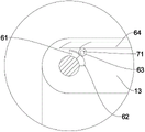
Furthermore, the displacement mechanism comprises an incomplete tooth block which is keyed on the output shaft of the stepping motor, a sliding groove and an arc-shaped groove for accommodating the incomplete tooth block to move are formed in the rotating piece, a gear which is meshed with the incomplete tooth block is rotatably arranged in the rotating piece, a displacement piece which is meshed with the gear is matched in the sliding groove in a sliding mode, and the right end of the displacement piece is connected with the pressure die. The gear is positioned in the middle of the arc-shaped groove. The device can drive an incomplete tooth block to rotate in an arc-shaped groove through an output shaft of a stepping motor, meanwhile, the incomplete tooth block drives a gear to rotate, the gear drives a displacement piece to move left, the displacement piece drives a pressure die to move left, the pressure die is attached to a bending die to clamp a straight pipe, the incomplete tooth block is abutted against the rear end face of the arc-shaped groove, the gear is fixed by the incomplete tooth block and does not rotate any more, then the incomplete tooth block pushes a rotating piece to rotate around the output shaft of the stepping motor and the central shaft of the bending die, so that the gear, the displacement piece and the pressure die are driven to rotate, the effect of bending the pipe is achieved, the rotating piece is reversely reset after the pipe is bent, then the incomplete tooth block drives the gear to reversely rotate, the gear drives the displacement piece to move right, the displacement piece drives the pressure die to move right to reset, the pressure die is separated from the bending, is convenient and quick.
Furthermore, the blocking mechanism comprises two ejector rods penetrating through the inclined plate and a rotating shaft which is in keyed joint with the center of the gear, an end face cam is in keyed joint with the top end of the rotating shaft, the two ejector rods respectively push against the left side and the right side of the working face of the end face cam, a limiting ring is arranged at the middle end of each ejector rod, a fixed block is arranged at the lower end of the inclined plate, and a spring connected with the limiting ring and the fixed block is sleeved outside each ejector rod. This setting can cooperate with displacement mechanism, when the pressure mould moves to the left, incomplete tooth piece drives the gear and overlooks and rotates half a circle, make left ejector pin decline through the end cam, the ejector pin on right side rises, the straight tube is blocked by the ejector pin on right side on the hang plate, after accomplishing the return bend, when the pressure mould moves to the right, incomplete tooth piece takes gear reversal half a circle, make left ejector pin rise through the end cam, the ejector pin on right side descends, at this in-process, a straight tube between the left and right sides ejector pin rolls down, and the straight tube at back is blocked by the ejector pin on right side, realize only at the in-process that the pressure mould moved to the right, just have a straight tube to roll down, in proper order automatic unloading.
Furthermore, the displacement piece comprises a rack meshed with the gear and a connecting block arranged on the right side of the upper end of the rack, and the connecting block is arranged at the lower end of the pressure die.
Further, when the incomplete tooth block props against the rear end face of the arc-shaped groove, the gear rotates for a half circle, and the teeth of the incomplete tooth block are meshed with the gear. During the rotation of the rotating part, the gear is fixed by the incomplete tooth block, so that the displacement part and the pressure die are fixed, and the straight pipe is prevented from not being clamped in the pipe bending process.
The invention has the advantages that: simple structure, convenient and fast can accomplish in proper order automatically and press from both sides tight straight tube, crooked straight tube, loosen the return bend, in proper order automatic unloading in proper order, need not operating fixture and can press from both sides tight pipe fitting at the in-process of return bend always, degree of automation is high.
Drawings
FIG. 1 is a perspective view according to the present invention;
FIG. 2 is a schematic structural diagram according to the present invention;
FIG. 3 is a front view according to the present invention;
FIG. 4 is a top view according to the present invention;
FIG. 5 is a sectional view A-A of FIG. 3;
FIG. 6 is a front view of the displacer and pressure die moving to the bottom left in accordance with the present invention;
FIG. 7 is a cross-sectional view B-B of FIG. 6;
FIG. 8 is a cross-sectional view of a rotating member rotating and bending a tube according to the present invention;
FIG. 9 is a cross-sectional view of the rotating member being reset and the bending being completed in accordance with the present invention;
FIG. 10 is an enlarged view of section C of FIG. 5;
fig. 11 is a perspective view of a displacement member according to the present invention.
Detailed Description
As shown in fig. 1 to 11, a pipe bender capable of automatic blanking comprises a base 1, a stepping motor 4 is arranged in the base 1, a platform 2 is arranged at the upper end of the base 1, a bending die 3 and a supporting block 8 are arranged at the upper end of the platform 2, a pressure die 5 is arranged at the right side of the bending die 3, a rotating groove is arranged at the rear end of the platform 2, a rotating member 13 rotatably arranged in the rotating groove is sleeved on an output shaft of the stepping motor 4, a displacement mechanism 6 for tightening and loosening the pressure die 5 and rotating the rotating member 13 is arranged in the rotating member 13, the displacement mechanism 6 is connected with the output shaft of the stepping motor 4 and the pressure die 5, a blanking mechanism for automatic blanking is arranged on the platform 2, the blanking mechanism comprises a blocking mechanism 7 connected on the displacement mechanism 6, side baffles 9 arranged at the front and rear sides of the upper end of the platform 2, a right baffle 10 positioned above the pressure die 5 is arranged between the side baffles 9, an inclined plate 11 connected on the, the right end of the inclined plate 11 is provided with a left baffle 12. The straight pipe is placed on the inclined plate, after each pipe bending is finished, one straight pipe is placed on the blocking mechanism to roll down, the straight pipe falls between the pressure die and the bending die under the gears of the left baffle, the right baffle and the side baffle, in the process that the pressure die moves to the left, the straight pipe can be clamped by the pressure die and the bending die, and meanwhile, the front end of the straight pipe is abutted by the abutting block, so that automatic blanking is realized.
The displacement mechanism 6 comprises an incomplete tooth block 61 which is keyed on an output shaft of the stepping motor 4, an arc-shaped groove 62 which is provided with a sliding groove and can accommodate the incomplete tooth block 61 to move is arranged on the rotating piece 13, a gear 63 which is meshed with the incomplete tooth block 61 is rotatably arranged in the rotating piece 13, a displacement piece 64 which is meshed with the gear 63 is arranged in the sliding groove in a sliding way, and the right end of the displacement piece 64 is connected with the pressure die 5. The gear is positioned in the middle of the arc-shaped groove. The device can drive an incomplete tooth block to rotate in an arc-shaped groove through an output shaft of a stepping motor, meanwhile, the incomplete tooth block drives a gear to rotate, the gear drives a displacement piece to move left, the displacement piece drives a pressure die to move left, the pressure die is attached to a bending die to clamp a straight pipe, the incomplete tooth block is abutted against the rear end face of the arc-shaped groove, the gear is fixed by the incomplete tooth block and does not rotate any more, then the incomplete tooth block pushes a rotating piece to rotate around the output shaft of the stepping motor and the central shaft of the bending die, so that the gear, the displacement piece and the pressure die are driven to rotate, the effect of bending the pipe is achieved, the rotating piece is reversely reset after the pipe is bent, then the incomplete tooth block drives the gear to reversely rotate, the gear drives the displacement piece to move right, the displacement piece drives the pressure die to move right to reset, the pressure die is separated from the bending, is convenient and quick.
The blocking mechanism 7 comprises two push rods 73 penetrating through the inclined plate 11 and a rotating shaft 71 which is in keyed connection with the center of the gear 63, an end face cam 72 is in keyed connection with the top end of the rotating shaft 71, the two push rods 73 are respectively abutted against the left side and the right side of the working face of the end face cam 72, a limiting ring 74 is arranged at the middle end of each push rod 73, a fixed block 75 is arranged at the lower end of the inclined plate 11, and a spring connected with the limiting ring 74 and the fixed block 75 is sleeved outside each push rod. This setting can cooperate with displacement mechanism, when the pressure mould moves to the left, incomplete tooth piece drives gear rotation half a circle, make left ejector pin decline through the end cam, the ejector pin on right side rises, the straight tube is blocked by the ejector pin on right side on the hang plate, after accomplishing the return bend, when the pressure mould moves to the right, incomplete tooth piece takes gear reversal half a circle, make left ejector pin rise through the end cam, the ejector pin on right side descends, at this in-process, a straight tube between the left and right sides ejector pin rolls down, and the straight tube at back is blocked by the ejector pin on right side, realize only moving to the right in-process at the pressure mould, just have a straight tube to roll down, just in order automatic unloading in proper order.
The displacement member 64 includes a rack 641 engaged with the gear 63, and a connection block 642 provided on the right side of the upper end of the rack 641, and the connection block 642 is provided at the lower end of the pressure die 5.
When the incomplete tooth block 61 abuts against the rear end face of the arc-shaped groove 62, the gear 63 rotates half a turn, and the teeth of the incomplete tooth block 61 mesh with the gear 63. During the rotation of the rotating part, the gear is fixed by the incomplete tooth block, so that the displacement part and the pressure die are fixed, and the straight pipe is prevented from not being clamped in the pipe bending process.
The working principle is as follows: when a pipe needs to be bent, the straight pipes are placed on the inclined plate, the straight pipes are blocked by the ejector rod on the left side, the straight pipes are placed between the bending die and the pressure die, then the stepping motor is started, the output shaft of the stepping motor drives the incomplete tooth block to rotate in the arc-shaped groove, meanwhile, the incomplete tooth block drives the gear to rotate for half a circle, the gear drives the displacement piece to move left, the displacement piece drives the pressure die to move left, the pressure die is attached to the bending die to clamp the straight pipes tightly, meanwhile, the gear drives the rotating shaft to rotate, the rotating shaft enables the ejector rod on the left side to descend through the end face cam, the ejector rod on the right side rises, the straight pipe on the inclined plate is blocked by the ejector rod on the right side, then the incomplete tooth block props against the rear end face of the arc-shaped groove, the gear is fixed by the incomplete tooth block, The displacement piece, the pressure die is rotatory, reach the effect of return bend, rotate the piece reversal and reset behind the return bend, incomplete tooth piece area gear reversal afterwards, the gear area moves to the right side, the displacement piece area pressure die moves to the right side and resets, pressure die and bending die separation, the staff takes out the return bend and the gear area pivot reversal simultaneously, make left ejector pin rise through the end cam, the ejector pin on right side descends, at this in-process, a straight tube between the left and right sides ejector pin rolls down, and the straight tube at back is blocked by the ejector pin on right side, realize only at the in-process that the pressure die moved to the right side, just have a straight tube to roll down, just in proper order automatic unloading in proper order, the staff is as long as to add the straight tube and get the return bend on the hang plate, just can accomplish.
The foregoing is only a preferred embodiment of the present invention, and it should be noted that, for those skilled in the art, various modifications and decorations can be made without departing from the technical principle of the present invention, and these modifications and decorations should also be regarded as the protection scope of the present invention.
Claims (5)
1. The utility model provides a bending machine of automatic unloading which characterized in that: including base (1), be equipped with step motor (4) in base (1), the upper end of base (1) is equipped with platform (2), the upper end of platform (2) is equipped with bending die (3), supports piece (8), the right side of bending die (3) is equipped with pressure die (5), the rear end of platform (2) is equipped with rotates the groove, the cover is equipped with to rotate on the output shaft of step motor (4) and establishes with rotating rotation inslot rotate piece (13), it is equipped with in (13) and is used for the elasticity to rotate pressure die (5) and rotate displacement mechanism (6) of rotating piece (13), displacement mechanism (6) are connected the output shaft of step motor (4) pressure die (5), be equipped with the unloading mechanism that is used for automatic unloading on platform (2), unloading mechanism is including connecting block mechanism (7) on displacement mechanism (6), Establish side shield (9) of both sides around platform (2) upper end, two be equipped with between side shield (9) and be located right baffle (10) of pressure mould (5) top, the left side of right baffle (10) is equipped with to be connected on platform (2) and with stop mechanism (7) matched with hang plate (11), the right-hand member of hang plate (11) is equipped with left baffle (12).
2. The bending machine capable of automatically blanking according to claim 1, wherein: the displacement mechanism (6) comprises an incomplete tooth block (61) which is in keyed connection with an output shaft of the stepping motor (4), a sliding groove and an arc-shaped groove (62) for accommodating the incomplete tooth block (61) are formed in the rotating part (13), a gear (63) meshed with the incomplete tooth block (61) is rotationally arranged in the rotating part (13), a displacement piece (64) meshed with the gear (63) is arranged in the sliding groove in a sliding mode, and the right end of the displacement piece (64) is connected with the pressure die (5).
3. The bender capable of automatic blanking according to claim 2, wherein: stop gear (7) including passing two ejector pins (73), the key joint of hang plate (11) are in pivot (71) at gear (63) center, the top key joint of pivot (71) has end cam (72), two ejector pin (73) are pushed up respectively the left and right sides of end cam (72) working face, the middle-end of ejector pin (73) is equipped with spacing ring (74), the lower extreme of hang plate (11) is equipped with fixed block (75), ejector pin (72) overcoat is equipped with the connection spacing ring (74), the spring of fixed block (75).
4. The bender capable of automatic blanking according to claim 2, wherein: the displacement piece (64) comprises a rack (641) meshed with the gear (63) and a connecting block (642) arranged on the right side of the upper end of the rack (641), and the connecting block (642) is arranged at the lower end of the pressure die (5).
5. The bender capable of automatic blanking according to any of the claims 2-4, characterized in that: when the incomplete tooth block (61) abuts against the rear end face of the arc-shaped groove (62), the gear (63) rotates for half a turn, and the teeth of the incomplete tooth block (61) are meshed with the gear (63).
Priority Applications (1)
| Application Number | Priority Date | Filing Date | Title |
|---|---|---|---|
| CN202010231538.9A CN111408639A (en) | 2020-03-27 | 2020-03-27 | Pipe bending machine capable of automatically discharging |
Applications Claiming Priority (1)
| Application Number | Priority Date | Filing Date | Title |
|---|---|---|---|
| CN202010231538.9A CN111408639A (en) | 2020-03-27 | 2020-03-27 | Pipe bending machine capable of automatically discharging |
Publications (1)
| Publication Number | Publication Date |
|---|---|
| CN111408639A true CN111408639A (en) | 2020-07-14 |
Family
ID=71485229
Family Applications (1)
| Application Number | Title | Priority Date | Filing Date |
|---|---|---|---|
| CN202010231538.9A Withdrawn CN111408639A (en) | 2020-03-27 | 2020-03-27 | Pipe bending machine capable of automatically discharging |
Country Status (1)
| Country | Link |
|---|---|
| CN (1) | CN111408639A (en) |
Citations (13)
| Publication number | Priority date | Publication date | Assignee | Title |
|---|---|---|---|---|
| JPH01122622A (en) * | 1987-11-09 | 1989-05-15 | Hitachi Ltd | Pipe bending device |
| CN101829927A (en) * | 2010-05-27 | 2010-09-15 | 张家港和升数控机床制造有限公司 | Automatic material jacking mechanism |
| WO2013068013A2 (en) * | 2011-11-08 | 2013-05-16 | Bend-It Aps | Portable electric pipe-bending apparatus |
| CN104525644A (en) * | 2014-12-05 | 2015-04-22 | 芜湖恒美电热器具有限公司 | Automatic pipe bending machine |
| CN106240185A (en) * | 2016-08-31 | 2016-12-21 | 杨志平 | Small Cylindrical workpiece stamp machine |
| CN207192097U (en) * | 2017-05-05 | 2018-04-06 | 佛山市宏石激光技术有限公司 | Tubing automatic charging device |
| CN207735491U (en) * | 2017-12-22 | 2018-08-17 | 襄阳龙思达智控技术有限公司 | A kind of bending machine automatic loading and unloading mechanism |
| CN108723141A (en) * | 2018-05-23 | 2018-11-02 | 文丹 | A kind of continuous bending machine of multi-angle |
| CN208374846U (en) * | 2018-07-03 | 2019-01-15 | 苏州卡茗特自动化设备有限公司 | Steel pipe automatic feed dividing collator |
| CN209753731U (en) * | 2019-04-18 | 2019-12-10 | 上海专一热处理有限公司 | Bending device with automatic feeding and discharging functions |
| CN110560593A (en) * | 2019-08-29 | 2019-12-13 | 安徽三花制冷新材料科技有限公司 | automatic feeding and discharging mechanism of pipe bender |
| CN209969270U (en) * | 2019-02-27 | 2020-01-21 | 重庆金仑机械制造有限责任公司 | Improved automatic pipe bending device |
| CN110817594A (en) * | 2019-11-06 | 2020-02-21 | 宁波爵盛科技有限公司 | Electric wire winding device |
-
2020
- 2020-03-27 CN CN202010231538.9A patent/CN111408639A/en not_active Withdrawn
Patent Citations (13)
| Publication number | Priority date | Publication date | Assignee | Title |
|---|---|---|---|---|
| JPH01122622A (en) * | 1987-11-09 | 1989-05-15 | Hitachi Ltd | Pipe bending device |
| CN101829927A (en) * | 2010-05-27 | 2010-09-15 | 张家港和升数控机床制造有限公司 | Automatic material jacking mechanism |
| WO2013068013A2 (en) * | 2011-11-08 | 2013-05-16 | Bend-It Aps | Portable electric pipe-bending apparatus |
| CN104525644A (en) * | 2014-12-05 | 2015-04-22 | 芜湖恒美电热器具有限公司 | Automatic pipe bending machine |
| CN106240185A (en) * | 2016-08-31 | 2016-12-21 | 杨志平 | Small Cylindrical workpiece stamp machine |
| CN207192097U (en) * | 2017-05-05 | 2018-04-06 | 佛山市宏石激光技术有限公司 | Tubing automatic charging device |
| CN207735491U (en) * | 2017-12-22 | 2018-08-17 | 襄阳龙思达智控技术有限公司 | A kind of bending machine automatic loading and unloading mechanism |
| CN108723141A (en) * | 2018-05-23 | 2018-11-02 | 文丹 | A kind of continuous bending machine of multi-angle |
| CN208374846U (en) * | 2018-07-03 | 2019-01-15 | 苏州卡茗特自动化设备有限公司 | Steel pipe automatic feed dividing collator |
| CN209969270U (en) * | 2019-02-27 | 2020-01-21 | 重庆金仑机械制造有限责任公司 | Improved automatic pipe bending device |
| CN209753731U (en) * | 2019-04-18 | 2019-12-10 | 上海专一热处理有限公司 | Bending device with automatic feeding and discharging functions |
| CN110560593A (en) * | 2019-08-29 | 2019-12-13 | 安徽三花制冷新材料科技有限公司 | automatic feeding and discharging mechanism of pipe bender |
| CN110817594A (en) * | 2019-11-06 | 2020-02-21 | 宁波爵盛科技有限公司 | Electric wire winding device |
Similar Documents
| Publication | Publication Date | Title |
|---|---|---|
| CN117066555B (en) | Machining mechanism and machining method for electric tool accessories | |
| CN110814074B (en) | Mould convenient to shaping unloading | |
| CN114453806B (en) | Automatic welding machine for bottom support plate of metal furniture upright post | |
| CN110900173A (en) | Be used for edges and corners bolt automatic assembly nut device | |
| CN117020290A (en) | A kind of prefabricated construction steel support processing equipment | |
| CN108480513B (en) | Positive and negative bidirectional hydraulic bending mechanism with bending baffle | |
| CN219151398U (en) | Stamping device convenient to unload | |
| CN112756434A (en) | Stamping and bending device for sheet metal processing | |
| CN106623485A (en) | Turbocharging oil return pipe forming device and process | |
| CN214024365U (en) | Index plate for trimmer | |
| CN108429413A (en) | A kind of vertical head-torsion machine of new energy motor | |
| CN221018982U (en) | Gear shaping machine tool for gear machining | |
| CN219966333U (en) | Hydraulic riveting machine | |
| CN114769446B (en) | Punch forming equipment and process for corrosion-resistant stainless steel seamless steel pipe fitting | |
| CN117505708A (en) | Rotary disc type multi-station vertical iron barrel sealing machine and method | |
| CN112589001B (en) | Automatic production line for special-shaped fixing parts | |
| CN113751548B (en) | Automatic bending device for special-shaped workpiece | |
| CN215515623U (en) | Automatic ceramic green sheet arranging device | |
| CN215511754U (en) | Dark jade cutting device | |
| CN111421029A (en) | Pipe bending machine with automatic push-out function | |
| CN212652409U (en) | Cold extrusion machining mechanism for gear shaft | |
| CN108817146B (en) | A kind of L shape workpiece automatic bending machine | |
| CN214813901U (en) | Novel pipe bending wheel device | |
| CN218574789U (en) | Positioning tool for hydraulic plate bending machine | |
| CN215658133U (en) | A high-efficiency cutting device for long stainless steel pipes |
Legal Events
| Date | Code | Title | Description |
|---|---|---|---|
| PB01 | Publication | ||
| PB01 | Publication | ||
| SE01 | Entry into force of request for substantive examination | ||
| SE01 | Entry into force of request for substantive examination | ||
| WW01 | Invention patent application withdrawn after publication | ||
| WW01 | Invention patent application withdrawn after publication |
Application publication date: 20200714 |