CN111396422A - Pilot type proportional flow valve and control method - Google Patents
Pilot type proportional flow valve and control method Download PDFInfo
- Publication number
- CN111396422A CN111396422A CN202010324662.XA CN202010324662A CN111396422A CN 111396422 A CN111396422 A CN 111396422A CN 202010324662 A CN202010324662 A CN 202010324662A CN 111396422 A CN111396422 A CN 111396422A
- Authority
- CN
- China
- Prior art keywords
- compensator
- valve
- valve core
- displacement
- control
- Prior art date
- Legal status (The legal status is an assumption and is not a legal conclusion. Google has not performed a legal analysis and makes no representation as to the accuracy of the status listed.)
- Pending
Links
- 238000000034 method Methods 0.000 title claims abstract description 26
- 238000006073 displacement reaction Methods 0.000 claims abstract description 89
- 238000011897 real-time detection Methods 0.000 claims abstract description 18
- 238000012545 processing Methods 0.000 claims description 16
- 238000012360 testing method Methods 0.000 claims description 5
- 230000005540 biological transmission Effects 0.000 claims description 2
- 238000012806 monitoring device Methods 0.000 claims description 2
- 238000010586 diagram Methods 0.000 description 6
- 238000004364 calculation method Methods 0.000 description 5
- 238000005516 engineering process Methods 0.000 description 3
- 230000009977 dual effect Effects 0.000 description 2
- RZVAJINKPMORJF-UHFFFAOYSA-N Acetaminophen Chemical compound CC(=O)NC1=CC=C(O)C=C1 RZVAJINKPMORJF-UHFFFAOYSA-N 0.000 description 1
- 230000003321 amplification Effects 0.000 description 1
- 238000004458 analytical method Methods 0.000 description 1
- 230000009286 beneficial effect Effects 0.000 description 1
- 230000033228 biological regulation Effects 0.000 description 1
- 230000006837 decompression Effects 0.000 description 1
- 238000001514 detection method Methods 0.000 description 1
- 238000004519 manufacturing process Methods 0.000 description 1
- 238000003199 nucleic acid amplification method Methods 0.000 description 1
- 230000001360 synchronised effect Effects 0.000 description 1
Images


Classifications
-
- F—MECHANICAL ENGINEERING; LIGHTING; HEATING; WEAPONS; BLASTING
- F15—FLUID-PRESSURE ACTUATORS; HYDRAULICS OR PNEUMATICS IN GENERAL
- F15B—SYSTEMS ACTING BY MEANS OF FLUIDS IN GENERAL; FLUID-PRESSURE ACTUATORS, e.g. SERVOMOTORS; DETAILS OF FLUID-PRESSURE SYSTEMS, NOT OTHERWISE PROVIDED FOR
- F15B13/00—Details of servomotor systems ; Valves for servomotor systems
- F15B13/02—Fluid distribution or supply devices characterised by their adaptation to the control of servomotors
- F15B13/021—Valves for interconnecting the fluid chambers of an actuator
-
- F—MECHANICAL ENGINEERING; LIGHTING; HEATING; WEAPONS; BLASTING
- F15—FLUID-PRESSURE ACTUATORS; HYDRAULICS OR PNEUMATICS IN GENERAL
- F15B—SYSTEMS ACTING BY MEANS OF FLUIDS IN GENERAL; FLUID-PRESSURE ACTUATORS, e.g. SERVOMOTORS; DETAILS OF FLUID-PRESSURE SYSTEMS, NOT OTHERWISE PROVIDED FOR
- F15B13/00—Details of servomotor systems ; Valves for servomotor systems
- F15B13/02—Fluid distribution or supply devices characterised by their adaptation to the control of servomotors
- F15B13/026—Pressure compensating valves
-
- F—MECHANICAL ENGINEERING; LIGHTING; HEATING; WEAPONS; BLASTING
- F15—FLUID-PRESSURE ACTUATORS; HYDRAULICS OR PNEUMATICS IN GENERAL
- F15B—SYSTEMS ACTING BY MEANS OF FLUIDS IN GENERAL; FLUID-PRESSURE ACTUATORS, e.g. SERVOMOTORS; DETAILS OF FLUID-PRESSURE SYSTEMS, NOT OTHERWISE PROVIDED FOR
- F15B19/00—Testing; Calibrating; Fault detection or monitoring; Simulation or modelling of fluid-pressure systems or apparatus not otherwise provided for
Landscapes
- Engineering & Computer Science (AREA)
- Physics & Mathematics (AREA)
- Fluid Mechanics (AREA)
- Mechanical Engineering (AREA)
- General Engineering & Computer Science (AREA)
- Chemical & Material Sciences (AREA)
- Analytical Chemistry (AREA)
- Fluid-Pressure Circuits (AREA)
- Control Of Fluid Pressure (AREA)
Abstract
一种先导型比例流量阀,包括连通主阀先导腔的比例先导阀,主阀与所述比例先导阀之间设置压差补偿器,压差补偿器对比例先导阀进出口压差进行补偿,压差补偿器为主动控制型压差补偿器,设置有阀芯线性控制装置及阀芯位移量实时检测装置;阀芯位移量实时检测装置的信号输出端口连接处理器;处理器连接控制所述阀芯线性控制装置。本发明解决了阀口采用压差传感器校正闭环控制流量方法,受压力传感器控制精度限制,压力传感器需要大的工作范围,但补偿压差相对较小,与系统中压力波动处于同一个数量级,压力微小变化造成流量大的波动,稳定性差的问题。
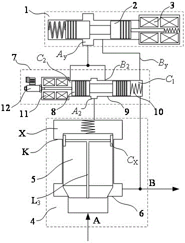
A pilot type proportional flow valve, comprising a proportional pilot valve communicating with a pilot chamber of a main valve, a pressure difference compensator is arranged between the main valve and the proportional pilot valve, and the pressure difference compensator compensates the pressure difference between the inlet and outlet of the proportional pilot valve, The differential pressure compensator is an active control type differential pressure compensator, which is provided with a valve core linear control device and a valve core displacement real-time detection device; the signal output port of the valve core displacement real-time detection device is connected to the processor; the processor is connected to control the Spool linear control device. The invention solves the problem that the valve port adopts the pressure difference sensor to correct the closed-loop flow control method, which is limited by the control accuracy of the pressure sensor, and the pressure sensor needs a large working range, but the compensation pressure difference is relatively small, which is in the same order of magnitude as the pressure fluctuation in the system. Small changes cause large fluctuations in flow and poor stability.
Description
技术领域technical field
本发明涉及液压控制技术领域,特别涉及一种先导型比例流量阀及控制方法。The invention relates to the technical field of hydraulic control, in particular to a pilot type proportional flow valve and a control method.
背景技术Background technique
比例流量控制阀是液压系统的重要元件之一,通过对流量的控制,实现对执行器速度的控制。比例流量控制阀有直动型和先导型2大类,对于大流量阀,通常采用先导型控制方式。The proportional flow control valve is one of the important components of the hydraulic system. It can control the speed of the actuator by controlling the flow. There are two types of proportional flow control valves: direct-acting and pilot-operated. For large-flow valves, pilot-operated control is usually used.
根据阀口流量计算公式,控制阀的输出流量是流量系数与阀开口面积和阀口前后压差平方根的乘积,紊流情况下(流量较大),流量系数被认为是常数,这样通过阀的流量就是阀开口面积与压差平方根的乘积。由于直接检测流量比较困难,目前的流量控制阀主要由两部分构成,一是控制阀开口面积的节流阀,再串联一个控制其阀口压差恒定的压差补偿器,目前的技术水平,节流阀的开口面积可以控制的非常精确,但压差补偿器所控制的压差值却受负载压力和流量的影响,变化比较大,这就造成阀输出流量的变化较大、控制精度降低。另外,阀的流量系数在小流量时,也是随着流动状态发生变化,所以在小流量时会造成阀输出流量与设定值的偏差较大。而且现有在主阀口直接串接压差补偿器的方式也减小了阀的通流能力,增大了阀的节流损失。According to the valve port flow calculation formula, the output flow rate of the control valve is the product of the flow coefficient and the valve opening area and the square root of the pressure difference before and after the valve port. Flow is the product of the valve opening area and the square root of the differential pressure. Due to the difficulty of directly detecting the flow rate, the current flow control valve is mainly composed of two parts, one is a throttle valve that controls the opening area of the valve, and a pressure difference compensator that controls the constant pressure difference of the valve port in series. The current technical level, The opening area of the throttle valve can be controlled very accurately, but the differential pressure value controlled by the differential pressure compensator is affected by the load pressure and flow, and the change is relatively large, which results in a large change in the output flow of the valve and a decrease in the control accuracy. . In addition, the flow coefficient of the valve also changes with the flow state when the flow is small, so the deviation between the valve output flow and the set value will be large when the flow is small. In addition, the existing method of directly connecting the differential pressure compensator in series at the main valve port also reduces the flow capacity of the valve and increases the throttling loss of the valve.
瑞典学者B.Anderson上世纪80年代初发明了流量放大型比例流量阀(Valvistor),其主阀的流量与先导阀的流量成正比,当阀的结构参数确定后,主阀按比例放大通过先导阀的流量。同时,为了消除比例先导阀进出口压差变化对通过其流量的影响,在主阀和比例先导阀之间串联一个小通径的定差减压阀,对比例先导阀进出口压差进行补偿,相对于在主阀口进行压差补偿的原理,简化了阀的结构。这样基本保证了先导阀进油口与出油口之间的压差恒定,但由于采用开环控制,控制流量仍然要受到压差补偿用定差减压阀液动力的影响,控制精度低,阀的机械结构也相对复杂,同时加大了阀的最低工作压力。The Swedish scholar B. Anderson invented the flow-amplifying proportional flow valve (Valvistor) in the early 1980s. The flow of the main valve is proportional to the flow of the pilot valve. When the structural parameters of the valve are determined, the main valve is proportionally enlarged and passed through the pilot valve valve flow. At the same time, in order to eliminate the influence of the pressure difference between the inlet and outlet of the proportional pilot valve on the flow through it, a small-diameter fixed differential pressure reducing valve is connected in series between the main valve and the proportional pilot valve to compensate the pressure difference between the inlet and outlet of the proportional pilot valve. , Compared with the principle of differential pressure compensation at the main valve port, the structure of the valve is simplified. In this way, the pressure difference between the oil inlet and the oil outlet of the pilot valve is basically guaranteed to be constant. However, due to the open-loop control, the control flow is still affected by the hydraulic power of the fixed difference pressure reducing valve used for pressure difference compensation, and the control accuracy is low. The mechanical structure of the valve is also relatively complex, and at the same time, the minimum working pressure of the valve is increased.
专利号为CN2011104114760的中国发明专利“先导流量闭环控制的流量阀及控制方法”,给出了一种在流量反馈型先导式比例节流阀的基础上、通过采用压力传感器实时检测先导阀口压差,对先导阀的开口按流量计算公式校正,从而维持先导阀流量不受压差变化的影响,再利用Valvistor阀专有的流量放大原理,主阀比例放大先导阀流量的控制方法。该方法虽然理论上能够克服直接在主阀进出油口串联压差补偿器的不足,但也产生了新的问题。首先,采用压力传感器检测阀口压差,成本很高,仅传感器的价格就远大于比例流量阀的价格,用户难以接受;其次,研究也表明,由于尚无耐高压力的压差传感器,而实际所需的压差值又非常小,与液压系统中压力波动值的范围接近,采用两支高压力范围的压力传感器做减法求取的压差值,就会受到系统压力波动的影响,使计算出的流量不稳定。如果对压差信号做深度滤波,又极大地影响阀的动态响应和控制性能,这一方法也非常不适用。The Chinese invention patent with the patent number of CN2011104114760 "Flow valve and control method for closed-loop control of pilot flow" provides a flow feedback type pilot proportional throttle valve based on the real-time detection of the pilot valve port pressure by using a pressure sensor. The opening of the pilot valve is corrected according to the flow calculation formula, so that the flow of the pilot valve is not affected by the change of pressure difference, and then the control method of the main valve proportionally amplifies the flow of the pilot valve by using the proprietary flow amplification principle of the Valvistor valve. Although this method can theoretically overcome the insufficiency of connecting the pressure difference compensator in series directly at the inlet and outlet of the main valve, it also creates new problems. First of all, the use of pressure sensors to detect the pressure difference at the valve port is very expensive. The price of the sensor alone is much higher than that of the proportional flow valve, which is difficult for users to accept; The actual required differential pressure value is very small, which is close to the range of the pressure fluctuation value in the hydraulic system. The differential pressure value obtained by subtracting two pressure sensors with a high pressure range will be affected by the system pressure fluctuation, making the The calculated flow is not stable. If the differential pressure signal is deeply filtered, which greatly affects the dynamic response and control performance of the valve, this method is also very unsuitable.
通过对现有技术和方法的分析,造成目前这种技术不足的原因可归结为,流量是阀口面积和阀口压差的双元函数,但目前的各种控制方法都只有一个阀口面积可控参数,而压差补偿器并不可控,只是被动地维持阀口压差基本恒定,如果能够将压差补偿器的压差值也作为可控参数,这样的阀就具有2个可控参数,与流量计算公式的双参数对应,就可以获得高的控制精度。Through the analysis of the existing technologies and methods, the reason for the current shortage of this technology can be attributed to the fact that the flow rate is a dual function of the valve port area and the valve port pressure difference, but the current various control methods only have one valve port area. Controllable parameters, but the pressure difference compensator is not controllable, but passively maintains the valve port pressure difference basically constant. If the pressure difference value of the pressure difference compensator can also be used as a controllable parameter, such a valve has two controllable parameters. The parameters correspond to the double parameters of the flow calculation formula, so that high control accuracy can be obtained.
发明内容SUMMARY OF THE INVENTION
本发明目的是解决现有比例流量阀结构复杂、流量控制精度低和压差损失大的技术问题;解决采用压力传感器控制,存在成本高、精度低等问题,提供一种结构简单、控制简单、压力损失小、流量控制精度高、调控范围大的先导型比例流量阀。The purpose of the invention is to solve the technical problems of complex structure, low flow control accuracy and large pressure difference loss of the existing proportional flow valve; Pilot-operated proportional flow valve with small pressure loss, high flow control accuracy and wide control range.
本发明采用的技术方案是:一种先导型比例流量阀,包括连通主阀先导腔的比例先导阀,所述主阀与所述比例先导阀之间设置压差补偿器,所述压差补偿器对所述比例先导阀进出口压差进行补偿,所述压差补偿器为主动控制型压差补偿器,设置有阀芯线性控制装置及阀芯位移量实时检测装置;所述阀芯位移量实时检测装置的信号输出端口连接处理器;The technical scheme adopted in the present invention is: a pilot type proportional flow valve, comprising a proportional pilot valve communicating with a pilot chamber of a main valve, a pressure difference compensator is arranged between the main valve and the proportional pilot valve, and the pressure difference compensation The differential pressure compensator is an active control type differential pressure compensator, which is provided with a valve core linear control device and a valve core displacement real-time detection device; the valve core displacement The signal output port of the quantitative real-time detection device is connected to the processor;
所述处理器连接控制所述阀芯线性控制装置;the processor is connected to control the spool linear control device;
所述处理器持续接收所述阀芯位移量实时检测装置实时输出的信号,与输入的初始控制信号对比处理后,生成控制信号至所述阀芯线性控制装置。The processor continuously receives the real-time output signal of the valve core displacement amount real-time detection device, and generates a control signal to the valve core linear control device after comparing and processing with the input initial control signal.
所述的一种先导型比例流量阀,其特征是:所述处理器包括运算模块,信号处理模块;所述初始控制信号包括所述阀芯线性控制装置所接收到的初始控制信号;The pilot type proportional flow valve is characterized in that: the processor includes an arithmetic module and a signal processing module; the initial control signal includes the initial control signal received by the valve core linear control device;
所述运算模块持续接收所述阀芯位移量实时检测装置实时输出的信号,与输入所述阀芯位移控制装置的信号对比处理后,输出处理信号至所述信号处理模块;The computing module continuously receives the real-time output signal of the valve core displacement real-time detection device, and outputs the processed signal to the signal processing module after comparing it with the signal input to the valve core displacement control device;
所述信号处理模块将所述运算模块输出的处理信号转化为控制信号,发送至所述阀芯位移控制装置。The signal processing module converts the processing signal output by the arithmetic module into a control signal, and sends it to the valve core displacement control device.
所述的一种先导型比例流量阀,其特征是:所述处理器还包括预估补偿模块;所述比例先导阀阀芯也设置有阀芯位移监测装置;The pilot type proportional flow valve is characterized in that: the processor further includes an estimation compensation module; the proportional pilot valve spool is also provided with a spool displacement monitoring device;
所述预估补偿模块通过所述比例先导阀阀芯位移量计算出比例先导阀开口面积,从而计算出所述比例先导阀的理论流量,即为所述压差补偿器的理论流量,将理论流量与压差补偿器阀芯位移量带入试验测得的压差-位移-流量三维曲线图,计算出需要补偿的液动力,并由信号处理模块转化为控制信号,叠加于所述运算模块输出的控制信号之上。The estimated compensation module calculates the opening area of the proportional pilot valve through the displacement of the proportional pilot valve spool, so as to calculate the theoretical flow rate of the proportional pilot valve, which is the theoretical flow rate of the differential pressure compensator. The displacement of the valve core of the flow and differential pressure compensator is brought into the three-dimensional curve of differential pressure-displacement-flow measured by the test to calculate the hydraulic force that needs to be compensated, and is converted into a control signal by the signal processing module, which is superimposed on the operation module. above the output control signal.
所述的一种先导型比例流量阀,其特征是:所述阀芯线性控制装置为比例电磁铁或电机驱动丝杠。The pilot type proportional flow valve is characterized in that: the linear control device of the valve core is a proportional electromagnet or a motor-driven lead screw.
所述的一种先导型比例流量阀,其特征是:当所述压差补偿器是比例电磁铁控制的压差补偿器时,包含有补偿器阀芯、补偿器阀体、补偿器弹簧、第Ⅰ比例电磁铁、位移传感器、补偿器进油口、补偿器出油口、补偿器弹簧腔和补偿器无弹簧腔;补偿器阀芯布置在补偿器阀体之中,补偿器弹簧一端作用在补偿器阀芯一个端面上,另一端作用在补偿器阀体上、并与补偿器阀芯形成补偿器弹簧腔,第Ⅰ比例电磁铁与补偿阀体连接、作用在补偿器阀芯另一端面上,并与补偿器阀芯、补偿器阀体形成补偿器无弹簧腔,位移传感器与第Ⅰ比例电磁铁集成安装。The pilot type proportional flow valve is characterized in that: when the differential pressure compensator is a differential pressure compensator controlled by a proportional electromagnet, it includes a compensator valve core, a compensator valve body, a compensator spring, The first proportional electromagnet, displacement sensor, compensator oil inlet, compensator oil outlet, compensator spring cavity and compensator no spring cavity; the compensator valve core is arranged in the compensator valve body, and one end of the compensator spring acts On one end face of the compensator spool, the other end acts on the compensator valve body and forms a compensator spring cavity with the compensator spool. The first proportional electromagnet is connected to the compensator valve body and acts on the other end of the compensator spool. On the end face, and with the compensator valve core and the compensator valve body, the compensator has no spring cavity, and the displacement sensor is integrated with the first proportional electromagnet.
所述的一种先导型比例流量阀,其特征是:所述的主动控制型压差补偿器是旋转电机驱动滚珠丝杠控制的压差补偿器时,包括补偿器阀芯、补偿器阀体、补偿器弹簧、旋转电机、轴承、滚珠丝杠、推杆、编码器、补偿器进油口、补偿器出油口、补偿器弹簧腔和补偿器无弹簧腔;补偿器阀芯布置在补偿器阀体之中,补偿器弹簧一端作用在补偿器阀芯一个端面上,另一端作用在补偿器阀体上、并与补偿器阀芯形成补偿器弹簧腔,旋转电机与补偿器阀体连接,旋转电机伸出轴通过轴承与滚珠丝杠连接,滚珠丝杠与推杆连接,推杆与补偿器阀芯机械连接,并与补偿器阀体、补偿器阀芯形成补偿器无弹簧腔C2。旋转电机带动滚珠丝杠旋转,通过滚珠丝杠将电机的旋转运动转换为直线运动,从而驱动推杆输出不同的力和位移。The pilot type proportional flow valve is characterized in that: when the active control type differential pressure compensator is a differential pressure compensator controlled by a ball screw driven by a rotating motor, it includes a compensator valve core and a compensator valve body. , compensator spring, rotating motor, bearing, ball screw, push rod, encoder, compensator oil inlet, compensator oil outlet, compensator spring cavity and compensator no spring cavity; the compensator spool is arranged in the compensator In the compensator valve body, one end of the compensator spring acts on one end face of the compensator valve core, the other end acts on the compensator valve body, and forms a compensator spring cavity with the compensator valve core, and the rotating motor is connected with the compensator valve body. , the extension shaft of the rotating motor is connected with the ball screw through the bearing, the ball screw is connected with the push rod, the push rod is mechanically connected with the compensator valve core, and forms a compensator without spring cavity C with the compensator valve body and the compensator valve core 2 . The rotary motor drives the ball screw to rotate, and the rotary motion of the motor is converted into linear motion through the ball screw, thereby driving the push rod to output different forces and displacements.
一种先导型比例流量阀的控制方法,其特征是:主阀先导腔依次连通压差补偿器和比例先导阀,所述压差补偿器设置有阀芯线性控制装置及阀芯位移量实时检测装置;所述压差补偿器能够进行压差控制和位移控制;A control method for a pilot type proportional flow valve, characterized in that: a main valve pilot chamber is connected to a differential pressure compensator and a proportional pilot valve in sequence, and the differential pressure compensator is provided with a valve core linear control device and real-time detection of valve core displacement device; the differential pressure compensator can perform differential pressure control and displacement control;
压差控制时,步骤如下:During differential pressure control, the steps are as follows:
步骤一:初始控制信号控制所述压差补偿器阀芯输出力,直接改变差压补偿器的补偿压差,补偿流量或压力变化带来的非线性控制偏差;Step 1: The initial control signal controls the output force of the differential pressure compensator spool, directly changes the compensated differential pressure of the differential pressure compensator, and compensates for the nonlinear control deviation caused by changes in flow or pressure;
位移控制时,步骤如下:During displacement control, the steps are as follows:
步骤一:初始控制信号控制所述压差补偿器阀芯输出力;Step 1: the initial control signal controls the output force of the differential pressure compensator spool;
步骤二:压差补偿器阀芯的实时位移量信号通过处理器调整,再次转化为压差补偿器阀芯控制信号,从而控制阀芯的输出力;Step 2: The real-time displacement signal of the spool of the differential pressure compensator is adjusted by the processor and converted into a control signal of the spool of the differential pressure compensator, thereby controlling the output force of the spool;
步骤三:经步骤二调试后,压差补偿器阀芯的实时位移量信号通过处理器调整,再次转化为压差补偿器阀芯控制信号,控制阀芯输出力和位移,反复调整,最终达到位移设定值;Step 3: After debugging in
如初始控制信号发生改变,则会重复步骤一至三。If the initial control signal is changed,
所述的一种先导型比例流量阀的控制方法,其特征是:所述阀芯线性控制装置为比例电磁铁,所述阀芯位移量实时检测装置为位移传感器;The control method for a pilot type proportional flow valve is characterized in that: the valve core linear control device is a proportional electromagnet, and the valve core displacement real-time detection device is a displacement sensor;
压差控制时:步骤一中,所述初始控制信号直接控制所述比例电磁铁输出力改变压差补偿器压差;During differential pressure control: in
位移控制时:步骤一中,所述初始控制信号控制所述比例电磁铁输出力;步骤二、三中,所述压差补偿器阀芯控制信号控制所述比例电磁铁输出力,从而控制阀芯的位移,最终达到位移设定值。During displacement control: in
所述的一种先导型比例流量阀的控制方法,其特征是:所述阀芯线性控制装置为电机和丝杠,所述电机匹配有电机驱动器,所述阀芯位移量实时检测装置为编码器;The control method of a pilot type proportional flow valve is characterized in that: the linear control device for the valve core is a motor and a lead screw, the motor is matched with a motor driver, and the real-time detection device for the displacement of the valve core is a code device;
压差控制时:步骤一中,所述初始控制信号输入所述电机驱动器,控制所述电机的转速或转矩,改变压差补偿器的补偿压差;During differential pressure control: in
位移控制时:步骤一中,所述初始控制信号输入所述电机驱动器,控制所述电机的转速或转矩;步骤二、三中,所述编码器检测电机转角,通过丝杠传动比转化为阀芯位移量输入处理器中,经处理器调整,再次转化为压差补偿器阀芯控制信号输入所述电机驱动器控制旋转电机13转速和/或转矩,最终控制补偿器阀芯位移。During displacement control: in
所述的一种先导型比例流量阀的控制方法,其特征是:所述初始控制信号转化为所述比例先导阀的理论流量,即为所述压差补偿器的理论流量,将理论流量与压差补偿器阀芯位移量带入试验测得的压差-位移-流量三维曲线图,计算出需要补偿的液动力,并由信号处理模块转化为控制信号,叠加于所述运算模块输出的控制信号之上,控制阀芯的输出力和位移。The control method for a pilot type proportional flow valve is characterized in that: the initial control signal is converted into the theoretical flow of the proportional pilot valve, that is, the theoretical flow of the differential pressure compensator, and the theoretical flow is equal to the theoretical flow of the proportional pilot valve. The displacement of the spool of the differential pressure compensator is brought into the three-dimensional curve of differential pressure-displacement-flow measured by the test to calculate the hydraulic force that needs to be compensated, and is converted into a control signal by the signal processing module, which is superimposed on the output of the operation module. Above the control signal, the output force and displacement of the spool are controlled.
与现有技术相比,本发明具有以下有益效果:Compared with the prior art, the present invention has the following beneficial effects:
本发明设计的新型主动控制型压差补偿器,解决阀口采用压差传感器校正闭环控制流量方法,受压力传感器控制精度限制,压力传感器需要大的工作范围,但补偿压差相对较小,与系统中压力波动处于同一个数量级,压力微小变化造成流量大的波动,稳定性差的问题。The novel active control differential pressure compensator designed by the present invention solves the problem that the valve port adopts the differential pressure sensor to correct the closed-loop flow control method, which is limited by the control accuracy of the pressure sensor, and the pressure sensor needs a large working range, but the compensation pressure difference is relatively small, and the pressure difference is relatively small. The pressure fluctuations in the system are in the same order of magnitude, and small changes in pressure cause large fluctuations in flow and poor stability.
本发明设计的新型主动控制型压差补偿器,采用电子控制单元可连续改变补偿器控制压差,并实时监控补偿器阀芯位置,控制补偿器阀芯处于最大开口,主阀就相当于比例节流阀,具有较流量控制2倍以上的最大流量;连续改变补偿器的压差值,就可连续控制主阀的额定输出流量,使阀具有节流与调速复合的控制功能,因而增大了主阀的流量调控范围,当需要大流量时采用节流控制,当需要精确控制流量或者是多执行器分配流量时,可以采用高精度流量控制功能。促进了流量控制阀的智能化,为进一步实施先进控制奠定了基础。解决了现有原理,在主阀阀口串接压差补偿器限制主阀输出流量控制范围的问题。The new type of active control differential pressure compensator designed by the invention adopts the electronic control unit to continuously change the control pressure differential of the compensator, and monitor the position of the compensator valve core in real time. When the valve core of the compensator is controlled to be at the maximum opening, the main valve is equivalent to a proportional The throttle valve has a maximum flow rate that is more than 2 times that of the flow control; continuously changing the differential pressure value of the compensator can continuously control the rated output flow of the main valve, so that the valve has a combined control function of throttling and speed regulation, thus increasing the The flow control range of the main valve is enlarged. When large flow is required, throttling control is used. When precise flow control or multi-actuator distribution flow is required, high-precision flow control function can be used. It promotes the intelligence of the flow control valve and lays the foundation for the further implementation of advanced control. The invention solves the problem of limiting the output flow control range of the main valve by connecting the pressure difference compensator in series at the valve port of the main valve according to the existing principle.
本发明设计了新型主动控制型压差补偿器,可实现补偿器压差值和其阀芯位移的双参数控制功能,通过检测补偿器阀芯位置,实时施加主动压差控制,可维持系统压差大范围变化时,补偿器控制的压差值恒定,增强了流量阀抗负载变化的调节刚性,具有好的稳态负载特性,从而提高了主阀的流量控制精度。可以解决现有技术受液动力变化影响,补偿器控制压差变化较大,造成流量控制精度低的问题。The invention designs a new type of active control differential pressure compensator, which can realize the dual parameter control function of the differential pressure value of the compensator and the displacement of its valve core. By detecting the position of the valve core of the compensator and applying active differential pressure control in real time, the system pressure can be maintained. When the difference changes in a large range, the pressure difference value controlled by the compensator is constant, which enhances the adjustment rigidity of the flow valve against load changes, and has good steady-state load characteristics, thereby improving the flow control accuracy of the main valve. It can solve the problem that the existing technology is affected by the change of hydraulic power, and the pressure difference controlled by the compensator changes greatly, resulting in low flow control accuracy.
本发明设计的新型主动控制型压差补偿器,可实现补偿器常开或常闭控制,解决了传统流量阀采用减压式补偿器响应滞后、负载压力阶跃起动流量超调大的问题。The novel active control type differential pressure compensator designed by the invention can realize the normally open or normally closed control of the compensator, and solve the problems that the traditional flow valve adopts the decompression type compensator to respond lag and the load pressure step start flow overshoot is large.
本发明设计的新型主动控制型压差补偿器,可适用阀的不同工况,基于工况需求匹配补偿器压差值,同样的阀口面积增益,减小补偿器压差值就可降低阀口流量增益,精细控制微小流量,提高执行器操控精度和平稳性。提高补偿器补偿压差值,就增大了阀口流量增益,增大阀的输出流量,可实现执行器快速动作。解决了现有恒定值压差补偿器,由于压差值较大,完全靠改变阀节流口形状控制微小流量,受制造难度和阀口形貌限制,微小流量控制精度低的问题。The new type of active control differential pressure compensator designed by the invention can be applied to different working conditions of the valve, and the differential pressure value of the compensator can be matched according to the requirements of the working conditions. The same valve port area gain can be reduced by reducing the differential pressure value of the compensator. Port flow gain, finely control the tiny flow, and improve the control accuracy and stability of the actuator. Increasing the compensation pressure difference value of the compensator increases the flow gain of the valve port, increases the output flow of the valve, and can realize the rapid action of the actuator. The existing constant-value differential pressure compensator, due to the large differential pressure value, completely controls the tiny flow by changing the shape of the valve orifice, and is limited by the difficulty of manufacturing and the shape of the valve port, and the control accuracy of the tiny flow is low.
附图说明Description of drawings
图1为本发明实施例1的结构原理图;1 is a schematic structural diagram of
图2为本发明实施例1的控制原理图;Fig. 2 is the control principle diagram of
图3为本发明实施例2的结构原理图;3 is a schematic structural diagram of
图4为本发明实施例2的控制原理图;4 is a control principle diagram of
图5为本发明实施例3的结构原理图;5 is a schematic structural diagram of
图6为本发明实施例3的控制原理图。FIG. 6 is a control principle diagram of
图中:1-比例先导阀,2-先导阀阀芯,3-先导阀比例电磁铁,Ay-先导阀进油口,By-先导阀出油口,4-主阀,5-主阀阀芯,6-主阀套7-主动控制型压差补偿器,8-补偿器阀芯,9-补偿器阀体,10-补偿器弹簧,11-第Ⅰ比例电磁铁,12-位移传感器,13-旋转电机,14-轴承,15-滚珠丝杠,16-推杆,17-第Ⅱ位移传感器,18-比例放大器,19-电机驱动器,20-编码器,21-处理器。In the figure: 1- proportional pilot valve, 2- pilot valve spool, 3- pilot valve proportional solenoid, A y - pilot valve inlet, B y - pilot valve outlet, 4- main valve, 5- main valve Valve spool, 6-main valve sleeve 7-active control type differential pressure compensator, 8-compensator spool, 9-compensator valve body, 10-compensator spring, 11-first proportional solenoid, 12-displacement Sensor, 13-rotating motor, 14-bearing, 15-ball screw, 16-putting rod, 17-second displacement sensor, 18-proportional amplifier, 19-motor driver, 20-encoder, 21-processor.
A-主阀进油口,B-主阀出油口,Cx-节流槽,K-节流边,L3-第Ⅲ流道,A2-补偿器进油口,B2-补偿器出油口,C1-补偿器弹簧腔,C2-补偿器无弹簧腔。A-main valve oil inlet, B-main valve oil outlet, Cx -throttle groove, K-throttle edge, L3- third passage, A2 - compensator oil inlet, B2 - compensation compensator outlet, C 1 - compensator spring chamber, C 2 - compensator no spring chamber.
具体实施方式Detailed ways
实施例一:Example 1:
如图1所示,一种先导型比例流量阀,包括比例先导阀1和主阀4。先导比例阀1包括有先导阀阀芯2、先导阀比例电磁铁3、先导阀进油口Ay和先导阀出油口By;主阀4包括有主阀阀芯5、主阀套6、主阀进油口A、主阀出油口B和主阀控制腔X;主阀进油口A通过主阀4第Ⅲ流道L3连通节流槽Cx,节流槽Cx通过主阀套6的节流边K与主阀4控制腔X相通。As shown in FIG. 1 , a pilot type proportional flow valve includes a
同时,在主阀4和先导比例阀1之间,增设有主动控制型压差补偿器7。主阀控制腔X与补偿器进油口A2连通,补偿器出油口B2同时与先导阀进油口Ay、补偿器无弹簧腔C2,先导阀出油口By同时与补偿器弹簧腔C1和主阀出油口B连通。At the same time, between the
主动控制型压差补偿器7采用比例电磁铁控制,包含有补偿器阀芯8、补偿器阀体9、补偿器弹簧10、第Ⅰ比例电磁铁11、位移传感器12、补偿器进油口A2、补偿器出油口B2、补偿器弹簧腔C1和补偿器无弹簧腔C2;补偿器阀芯8布置在补偿器阀体9之中,补偿器弹簧10一端作用在补偿器阀芯8一个端面上,另一端作用在补偿器阀体9上、并与补偿器阀芯8形成补偿器弹簧腔C1,第Ⅰ比例电磁铁11与补偿器阀体9连接、作用在补偿器阀芯8另一端面上,并与补偿器阀芯8、补偿器阀体9形成补偿器无弹簧腔C2,位移传感器12与第Ⅰ比例电磁铁11集成安装,第Ⅰ比例电磁铁11是单向比例电磁铁和双向比例电磁铁中的一种。Active control type differential pressure compensator 7 is controlled by proportional electromagnet, including
如图2所示,主动控制型压差补偿器7采用比例电磁铁控制时,可进行压差控制和位移控制,具体控制方法为:压差控制时,输入信号ui通过比例放大器18控制第Ⅰ比例电磁铁11输出力,从而改变补偿器7补偿压差Δp,改善了主阀4的流量控制特性和精度;位移控制时,位移传感器12检测补偿器阀芯位移x,然后将检测到的补偿器阀芯8位移x信号输入处理器21中,乘以位移增益系数Kf转化为反馈信号uif,并与输入信号ui一同输入运算模块,比较得到偏差值,并采用比例-积分-微分算法调整,调整后的信号通过信号处理模块转化为新的控制信号控制第Ⅰ比例电磁铁11输出力,上述步骤往复进行,实现补偿器阀芯8位移x的连续控制。As shown in Fig. 2, when the active control type differential pressure compensator 7 is controlled by the proportional electromagnet, it can perform differential pressure control and displacement control. The specific control method is as follows: during differential pressure control, the input signal u i controls the first Ⅰ The
实施例二:Embodiment 2:
如图3所示,本发明一种新型先导型比例流量阀及其控制方法的第二种实施方式,在结构组成、连接关系上与第一种实施方式相同,区别在于:As shown in FIG. 3 , the second embodiment of a novel pilot type proportional flow valve and its control method of the present invention is the same as the first embodiment in terms of structural composition and connection relationship, and the differences are:
主动控制型压差补偿器7采用旋转电机13驱动滚珠丝杠15控制,包括补偿器阀芯8、补偿器阀体9、补偿器弹簧10、旋转电机13、轴承14、滚珠丝杠15、推杆16、编码器20、补偿器进油口A2、补偿器出油口B2、补偿器弹簧腔C1和补偿器无弹簧腔C2;补偿器阀芯8布置在补偿器阀体9之中,补偿器弹簧10一端作用在补偿器阀芯8的一个端面上,另一端作用在补偿器阀体9上、并与补偿器阀芯8形成补偿器弹簧腔C1,旋转电机与补偿器阀体连接,旋转电机13伸出轴通过轴承14与滚珠丝杠15连接,滚珠丝杠15与推杆16连接,推杆16与补偿器阀芯8机械连接,并与补偿器阀体9、补偿器阀芯8形成补偿器无弹簧腔C2。旋转电机13是直流电机、同步电机和异步电机中的一种。旋转电机13带动滚珠丝杠15旋转,通过滚珠丝杠15将电机的旋转运动转换为直线运动,驱动推杆16输出不同的力或位移。Active control type differential pressure compensator 7 is controlled by
如图4所示,主动控制型压差补偿器7采用旋转电机13驱动滚珠丝杠15控制时,能进行压差控制或位移控制,具体控制方法为:压差控制时,输入信号um通过电机驱动器19控制旋转电机13转速和/或转矩,从而改变补偿器7补偿压差Δp,改善了主阀4的流量控制特性和精度;位移控制时,编码器20检测旋转电机13转角,并通过丝杠传动比转化为补偿器阀芯8位移x输入处理器21中,然后将检测补偿器阀芯8位移x乘以电机增益Kn转化为反馈信号umf,与输入信号um一同输入运算模块,比较得到偏差值,采用比例-积分-微分算法调整,调整后的信号通过信号处理模块转化为新的控制信号控制旋转电机13转速或转矩,上述步骤往复进行,实现补偿器阀芯8位移x的连续闭环控制。As shown in FIG. 4 , the active control type differential pressure compensator 7 can perform differential pressure control or displacement control when the
实施例三:Embodiment three:
如图5所示,本发明一种新型先导型比例流量阀及其控制方法的第三种实施方式,在结构组成、连接关系上与实施例一相同,区别是:主阀4设置有第Ⅱ位移传感器17;第Ⅱ位移传感器17与主阀阀芯5连接,实时检测主阀阀芯5位移。As shown in FIG. 5 , the third embodiment of a novel pilot type proportional flow valve and its control method of the present invention is the same as the first embodiment in terms of structural composition and connection relationship, except that the
如图6所示,主动控制型压差补偿器7进行压差控制时,与实施例一步骤相同,并进一步增设非线性补偿算法。非线性补偿算法为:根据公式
Claims (10)
Priority Applications (2)
| Application Number | Priority Date | Filing Date | Title |
|---|---|---|---|
| CN202010324662.XA CN111396422A (en) | 2020-04-23 | 2020-04-23 | Pilot type proportional flow valve and control method |
| CN202010686510.4A CN111609012B (en) | 2020-04-23 | 2020-07-16 | Pilot type proportional flow valve and control method |
Applications Claiming Priority (1)
| Application Number | Priority Date | Filing Date | Title |
|---|---|---|---|
| CN202010324662.XA CN111396422A (en) | 2020-04-23 | 2020-04-23 | Pilot type proportional flow valve and control method |
Publications (1)
| Publication Number | Publication Date |
|---|---|
| CN111396422A true CN111396422A (en) | 2020-07-10 |
Family
ID=71437293
Family Applications (2)
| Application Number | Title | Priority Date | Filing Date |
|---|---|---|---|
| CN202010324662.XA Pending CN111396422A (en) | 2020-04-23 | 2020-04-23 | Pilot type proportional flow valve and control method |
| CN202010686510.4A Active CN111609012B (en) | 2020-04-23 | 2020-07-16 | Pilot type proportional flow valve and control method |
Family Applications After (1)
| Application Number | Title | Priority Date | Filing Date |
|---|---|---|---|
| CN202010686510.4A Active CN111609012B (en) | 2020-04-23 | 2020-07-16 | Pilot type proportional flow valve and control method |
Country Status (1)
| Country | Link |
|---|---|
| CN (2) | CN111396422A (en) |
Cited By (7)
| Publication number | Priority date | Publication date | Assignee | Title |
|---|---|---|---|---|
| CN112576566A (en) * | 2020-12-07 | 2021-03-30 | 重庆红江机械有限责任公司 | Displacement feedback proportional flow control valve |
| CN112780625A (en) * | 2021-01-25 | 2021-05-11 | 南京机电职业技术学院 | Flow control valve with pressure compensation and high-precision flow control method |
| CN114370521A (en) * | 2022-01-13 | 2022-04-19 | 中国铁建重工集团股份有限公司 | Hysteresis compensation control method and system for electric proportional relief valve |
| CN115573965A (en) * | 2022-12-07 | 2023-01-06 | 太原理工大学 | Multifunctional electro-hydraulic flow control valve and flow control method |
| CN116850415A (en) * | 2023-07-20 | 2023-10-10 | 北京航空航天大学 | Novel self-stabilizing control method and system for impedance flow of proportional valve of breathing machine |
| CN120007802A (en) * | 2025-02-12 | 2025-05-16 | 西安航天远征流体控制股份有限公司 | A pilot-operated explosion-proof flow control valve |
| AU2022430010B2 (en) * | 2022-04-24 | 2025-08-14 | Taiyuan University Of Technology | Digital speed regulating valve for aligning hydraulic supports in fully mechanized mining face and control method thereof |
Families Citing this family (3)
| Publication number | Priority date | Publication date | Assignee | Title |
|---|---|---|---|---|
| CN114111922B (en) * | 2021-11-22 | 2024-12-31 | 黑龙江农业工程职业学院 | Microfluidic detector and detection method |
| CN116225081B (en) * | 2023-03-10 | 2025-12-09 | 北京理工大学 | Dynamic hysteresis compensation method and system for micro-flow sensor |
| CN120205395B (en) * | 2025-05-27 | 2025-09-16 | 太原理工大学 | An automatic gluing device and method for the plastic liner and valve seat of a type IV hydrogen storage bottle |
Family Cites Families (7)
| Publication number | Priority date | Publication date | Assignee | Title |
|---|---|---|---|---|
| US4768540A (en) * | 1987-04-20 | 1988-09-06 | Atsugi Motor Parts Company, Limited | Flow control apparatus |
| CA2013481A1 (en) * | 1989-05-03 | 1990-11-03 | Gene R. St. Germain | Load responsive flow amplified control system |
| KR20110015696A (en) * | 2008-06-11 | 2011-02-16 | 이턴 코포레이션 | Auto-tuning electric-hydraulic valve |
| CN102425581B (en) * | 2011-12-12 | 2015-03-25 | 太原理工大学 | Pilot flow closed-loop controlled flow valve and control method |
| CN108612712B (en) * | 2018-04-10 | 2020-06-12 | 山西大学 | Electro-hydraulic proportional flow valve for active pilot control and control method |
| CN109441905B (en) * | 2018-12-26 | 2020-01-07 | 太原理工大学 | A variable pressure differential load-sensing multi-way valve |
| CN109630491B (en) * | 2018-12-26 | 2021-01-08 | 太原理工大学 | Electric control compensation two-way proportional flow valve |
-
2020
- 2020-04-23 CN CN202010324662.XA patent/CN111396422A/en active Pending
- 2020-07-16 CN CN202010686510.4A patent/CN111609012B/en active Active
Cited By (9)
| Publication number | Priority date | Publication date | Assignee | Title |
|---|---|---|---|---|
| CN112576566A (en) * | 2020-12-07 | 2021-03-30 | 重庆红江机械有限责任公司 | Displacement feedback proportional flow control valve |
| CN112780625A (en) * | 2021-01-25 | 2021-05-11 | 南京机电职业技术学院 | Flow control valve with pressure compensation and high-precision flow control method |
| CN114370521A (en) * | 2022-01-13 | 2022-04-19 | 中国铁建重工集团股份有限公司 | Hysteresis compensation control method and system for electric proportional relief valve |
| CN114370521B (en) * | 2022-01-13 | 2024-02-02 | 中国铁建重工集团股份有限公司 | A hysteresis compensation control method and system for electric proportional relief valve |
| AU2022430010B2 (en) * | 2022-04-24 | 2025-08-14 | Taiyuan University Of Technology | Digital speed regulating valve for aligning hydraulic supports in fully mechanized mining face and control method thereof |
| CN115573965A (en) * | 2022-12-07 | 2023-01-06 | 太原理工大学 | Multifunctional electro-hydraulic flow control valve and flow control method |
| US12000504B1 (en) | 2022-12-07 | 2024-06-04 | Taiyuan University Of Technology | Multifunctional electro-hydraulic flow control valve and flow control method |
| CN116850415A (en) * | 2023-07-20 | 2023-10-10 | 北京航空航天大学 | Novel self-stabilizing control method and system for impedance flow of proportional valve of breathing machine |
| CN120007802A (en) * | 2025-02-12 | 2025-05-16 | 西安航天远征流体控制股份有限公司 | A pilot-operated explosion-proof flow control valve |
Also Published As
| Publication number | Publication date |
|---|---|
| CN111609012B (en) | 2022-03-04 |
| CN111609012A (en) | 2020-09-01 |
Similar Documents
| Publication | Publication Date | Title |
|---|---|---|
| CN111609012A (en) | A kind of pilot type proportional flow valve and control method | |
| CN109630491B (en) | Electric control compensation two-way proportional flow valve | |
| CN102425581B (en) | Pilot flow closed-loop controlled flow valve and control method | |
| CN111352450B (en) | Digital proportional valve flow control system and method | |
| US20250293060A1 (en) | Pressure control method and apparatus, and semiconductor process device | |
| CN108180180B (en) | Double-hydraulic-cylinder flow compensation synchronous erecting device and control method thereof | |
| CN115961669B (en) | Pilot flow soft closed loop main stage amplification type flow control method, system and valve | |
| CN117970803B (en) | A speed shift approach and disturbance compensation control method for a pump-controlled electro-hydraulic steering system | |
| CN110725817A (en) | A high-efficiency control method for an electro-hydraulic position servo system with independent inlet and outlet adjustment based on proportional relief valve | |
| CN108980208B (en) | Ultrahigh-precision pressure control device | |
| CN109114292B (en) | A kind of Pilotoperated reducing valve pilot stage drive characteristic detection method | |
| CN113859197A (en) | Solenoid valve hydraulic pressure control method and system based on valve core position estimation | |
| CN118640198A (en) | An electro-hydraulic controlled proportional flow valve and control method thereof | |
| CN100494698C (en) | Dynamic compensation hydraulic pressure servo valve null shift method | |
| CN115585164A (en) | Intelligent walking type pushing system | |
| CN117245660B (en) | Pressure and flow matching control method for robot hydraulic power source | |
| CN101865172B (en) | Active piloted active servo proportional valve | |
| WO2024140139A1 (en) | Digital-hydraulic flow matching system and control method therefor | |
| CN114370521B (en) | A hysteresis compensation control method and system for electric proportional relief valve | |
| CN111288082A (en) | Control system of single-degree-of-freedom magnetic-liquid double-suspension bearing | |
| CN121111837A (en) | A pressure closed-loop energy control system and method for a hydraulic station | |
| CN118817151B (en) | A calibration device and method for a liquid-gas linked pressure sensor | |
| CN106837911B (en) | Small-power servomotor drives pilot-operated type servo inserted valve and its closed loop control method | |
| CN110725823B (en) | A Cartridge Two-Stage Proportional Speed Control Valve Based on Pressure Ascent Rate Detector | |
| CN206754025U (en) | Small-power servomotor drives pilot-operated type servo inserted valve |
Legal Events
| Date | Code | Title | Description |
|---|---|---|---|
| PB01 | Publication | ||
| PB01 | Publication | ||
| SE01 | Entry into force of request for substantive examination | ||
| SE01 | Entry into force of request for substantive examination | ||
| WD01 | Invention patent application deemed withdrawn after publication |
Application publication date: 20200710 |
|
| WD01 | Invention patent application deemed withdrawn after publication |