CN111395236A - Bridge road surface cleaning device - Google Patents
Bridge road surface cleaning device Download PDFInfo
- Publication number
- CN111395236A CN111395236A CN202010358928.2A CN202010358928A CN111395236A CN 111395236 A CN111395236 A CN 111395236A CN 202010358928 A CN202010358928 A CN 202010358928A CN 111395236 A CN111395236 A CN 111395236A
- Authority
- CN
- China
- Prior art keywords
- wheel
- sliding
- spring
- main board
- motor
- Prior art date
- Legal status (The legal status is an assumption and is not a legal conclusion. Google has not performed a legal analysis and makes no representation as to the accuracy of the status listed.)
- Withdrawn
Links
- 238000004140 cleaning Methods 0.000 title claims abstract description 65
- XLYOFNOQVPJJNP-UHFFFAOYSA-N water Substances O XLYOFNOQVPJJNP-UHFFFAOYSA-N 0.000 claims abstract description 77
- 239000000428 dust Substances 0.000 claims description 83
- 238000007790 scraping Methods 0.000 claims description 37
- 238000005507 spraying Methods 0.000 claims description 12
- 238000003825 pressing Methods 0.000 claims description 10
- 238000010408 sweeping Methods 0.000 claims description 9
- 229910000838 Al alloy Inorganic materials 0.000 claims description 3
- 238000010586 diagram Methods 0.000 description 10
- 238000005457 optimization Methods 0.000 description 8
- 230000001502 supplementing effect Effects 0.000 description 5
- 238000000034 method Methods 0.000 description 3
- 238000007599 discharging Methods 0.000 description 2
- 230000003044 adaptive effect Effects 0.000 description 1
- 238000007792 addition Methods 0.000 description 1
- 230000009286 beneficial effect Effects 0.000 description 1
- 239000000463 material Substances 0.000 description 1
- 238000012986 modification Methods 0.000 description 1
- 230000004048 modification Effects 0.000 description 1
- 238000005070 sampling Methods 0.000 description 1
- 238000006467 substitution reaction Methods 0.000 description 1
Images




Classifications
-
- E—FIXED CONSTRUCTIONS
- E01—CONSTRUCTION OF ROADS, RAILWAYS, OR BRIDGES
- E01H—STREET CLEANING; CLEANING OF PERMANENT WAYS; CLEANING BEACHES; DISPERSING OR PREVENTING FOG IN GENERAL CLEANING STREET OR RAILWAY FURNITURE OR TUNNEL WALLS
- E01H1/00—Removing undesirable matter from roads or like surfaces, with or without moistening of the surface
- E01H1/005—Mobile installations, particularly for upkeeping in situ road or railway furniture, for instance road barricades, traffic signs; Mobile installations particularly for upkeeping tunnel walls
-
- E—FIXED CONSTRUCTIONS
- E01—CONSTRUCTION OF ROADS, RAILWAYS, OR BRIDGES
- E01H—STREET CLEANING; CLEANING OF PERMANENT WAYS; CLEANING BEACHES; DISPERSING OR PREVENTING FOG IN GENERAL CLEANING STREET OR RAILWAY FURNITURE OR TUNNEL WALLS
- E01H1/00—Removing undesirable matter from roads or like surfaces, with or without moistening of the surface
- E01H1/08—Pneumatically dislodging or taking-up undesirable matter or small objects; Drying by heat only or by streams of gas; Cleaning by projecting abrasive particles
- E01H1/0827—Dislodging by suction; Mechanical dislodging-cleaning apparatus with independent or dependent exhaust, e.g. dislodging-sweeping machines with independent suction nozzles ; Mechanical loosening devices working under vacuum
- E01H1/0836—Apparatus dislodging all of the dirt by suction ; Suction nozzles
- E01H1/0845—Apparatus dislodging all of the dirt by suction ; Suction nozzles with mechanical loosening or feeding instruments for the dirt to be sucked- up, e.g. brushes, scrapers
-
- E—FIXED CONSTRUCTIONS
- E01—CONSTRUCTION OF ROADS, RAILWAYS, OR BRIDGES
- E01H—STREET CLEANING; CLEANING OF PERMANENT WAYS; CLEANING BEACHES; DISPERSING OR PREVENTING FOG IN GENERAL CLEANING STREET OR RAILWAY FURNITURE OR TUNNEL WALLS
- E01H1/00—Removing undesirable matter from roads or like surfaces, with or without moistening of the surface
- E01H1/10—Hydraulically loosening or dislodging undesirable matter; Raking or scraping apparatus ; Removing liquids or semi-liquids e.g., absorbing water, sliding-off mud
- E01H1/101—Hydraulic loosening or dislodging, combined or not with mechanical loosening or dislodging, e.g. road washing machines with brushes or wipers
- E01H1/103—Hydraulic loosening or dislodging, combined or not with mechanical loosening or dislodging, e.g. road washing machines with brushes or wipers in which the soiled loosening or washing liquid is removed, e.g. by suction
Landscapes
- Engineering & Computer Science (AREA)
- Architecture (AREA)
- Civil Engineering (AREA)
- Structural Engineering (AREA)
- Cleaning In General (AREA)
Abstract
The invention relates to a cleaning device, in particular to a bridge pavement cleaning device which comprises a vehicle pedal, cleaning wheels, a collecting box, high-pressure water and a moving device, wherein the device can move along the pavement of a bridge, can clean the pavement firstly, then clean the pavement with the high-pressure water and discharge the cleaning water, can not obstruct the running of a vehicle, the cross section of the vehicle pedal is trapezoidal, the cleaning wheels are positioned at the lower part of the vehicle pedal, the collecting box is positioned at the middle part of the vehicle pedal, the high-pressure water is positioned at the rear part of the vehicle pedal, and the moving device is fixed on the side surface of the vehicle pedal.
Description
Technical Field
The invention relates to a cleaning device, in particular to a bridge pavement cleaning device.
Background
The bridge pavement cleaning device is designed because the road surface cleaning of the bridge is relatively troublesome, especially for the bridge with a long length.
Disclosure of Invention
The invention mainly solves the technical problem of providing a bridge road surface cleaning device which can move along the road surface of a bridge, can clean the road surface firstly, then clean the road surface by high-pressure water, and then discharge the cleaning water, and can not obstruct the running of vehicles.
In order to solve the technical problems, the invention relates to a cleaning device, in particular to a bridge pavement cleaning device which comprises a vehicle pedal, cleaning wheels, a collecting box, high-pressure water and a moving device.
The cross section of the vehicle pedal is trapezoidal, the cleaning wheel is positioned at the lower part of the vehicle pedal, the collecting box is positioned at the middle part of the vehicle pedal, the high-pressure water is positioned at the rear part of the vehicle pedal, and the moving device is fixed on the side surface of the vehicle pedal.
As a further optimization of the technical scheme, the pedal plate of the bridge road surface cleaning device comprises a main plate, a front plate, a rear plate, air vents, two spring seats, two sliding grooves, two transverse sliding grooves and two supports, wherein the upper part of the main plate is rectangular, the side surface of the main plate is trapezoidal, the front plate is positioned at the front part of the main plate, the rear plate is positioned at the rear part of the main plate, the air vents are positioned at two sides of the main plate, the two spring seats are fixed at the lower part of the inner side of the main plate, the two sliding grooves are positioned at the inner side of the main plate, the two transverse sliding grooves are positioned above the sliding grooves, the two supports are positioned at the inner side of the main plate.
As a further optimization of the technical scheme, the cleaning wheel of the bridge pavement cleaning device comprises a dust cover, a rotating wheel, a scraping plate and a dust collector, wherein the dust cover is fixed at the lower part of a main board, the outer part of the dust cover is square, the inner part of the dust cover is cylindrical, a rectangular opening is formed in the side surface of the dust cover, one end of the rotating wheel is connected with the dust collector, the scraping plate is in contact with the rotating wheel, and the dust collector is fixed at the outer side of the main board; the dust cover comprises connecting seats, scraping grooves and four spring columns, the connecting seats are located at two ends of the dust cover, four through holes are processed in the connecting seats, the connecting seats are connected with the main board through screws, the scraping grooves are located on the side face of the dust cover, the number of the spring columns is four, and the spring columns are connected with the scraper; the rotating wheel comprises a cleaning rotating wheel and a connector, the connectors are arranged at two ends of the cleaning rotating wheel, a hexagonal prism groove is arranged at one end of the connector, and the connector is connected with the dust collector; the scraper comprises transverse scrapers, buffer springs, a connecting plate, two supplementing springs and spring frames, the transverse scrapers are cuboid, the transverse scrapers are in sliding fit with the scraping grooves, the number of the buffer springs is four, one ends of the buffer springs are in contact with the dust cover, one ends of the buffer springs are connected with the connecting plate, the connecting plate is provided with two connecting plates, the connecting plate is located on the same side of the transverse scrapers, the number of the supplementing springs is four, one ends of the supplementing springs are in contact with the connecting plate, one ends of the supplementing springs are in contact with the spring frames, the number of; the dust collector comprises a dust hood, a driving motor, three fan blades, a belt, a connecting pin and a screw rod, wherein one side of the dust hood is connected with a main board through screws, the dust hood is communicated with air holes, the dust hood is provided with three through holes, the driving motor is fixed on one side of the dust hood, the three fan blades are arranged, the fan blades are in sliding fit with the dust hood, the belt is connected with the fan blades, the belt is connected with the connecting pin, one end of the connecting pin is a hexagonal prism, the connecting pin is connected with a rotating wheel, the middle of the connecting pin is in sliding fit with the dust hood, teeth are machined at one end of the connecting pin, the screw rod is fixed on a rotating shaft of the driving motor.
As a further optimization of the technical scheme, the collecting box of the bridge pavement cleaning device comprises a box body, two position-adaptive springs, two water rollers, a water discharge pipe, a motor, a sliding ring, an upper sliding block, a connecting block, a middle connecting block, a linking groove, a lower sliding block and a water discharge pump, wherein the box body is a cuboid, one side of the box body is provided with an opening, the lower part of the opening side of the box body is provided with a chute, the position-adaptive springs are sleeved on a spring seat, the upper parts of the position-adaptive springs are in contact with a main board, the water rollers are positioned on the opening side of the box body, the water rollers are in sliding fit with the box body, the water rollers are provided with grooves, the lower parts of the water discharge pipe are connected with the water discharge pump, the upper parts of the motor are fixed on the lower part of the main board, the sliding ring is fixed on a rotating shaft of, the lower part of the middle connecting block is connected with the lower sliding block, the chain connecting groove is fixed on the upper part of the box body, the lower part of the lower sliding block is in sliding fit with the chain connecting groove, and the drainage pump is positioned inside the box body.
As a further optimization of the technical scheme, the high-pressure water of the bridge pavement cleaning device comprises a water spraying cylinder, an adjusting wheel, a water scraping plate, a limiting plate, two pressing springs and a trapezoidal sliding block, wherein the water spraying cylinder is in sliding fit with a main plate, the adjusting wheel is positioned at one end of the water spraying cylinder, the adjusting wheel is in sliding fit with the main plate, the water scraping plate is in sliding fit with a sliding groove, the limiting plate is positioned at the upper part of the water scraping plate, two cylinders are arranged at the upper part of the sliding groove, the two pressing springs are arranged, the upper part of each pressing spring is connected with the lower part of the trapezoidal sliding block, the lower part of each pressing spring is connected with the limiting plate, the upper part of the trapezoidal sliding.
As a further optimization of the technical scheme, the moving device of the bridge pavement cleaning device comprises a link base, a link rod, a transverse plate, a belt wheel, a first belt, a first motor, a second motor, a chain, a first chain wheel, a second chain wheel, a motor chain wheel, a clamping block, a clamping spring, a driven wheel, a driving shaft and a driving wheel, wherein the link base is connected with a main plate, the lower part of the link rod is forked, the link rod is connected with the link base, the upper part of the link rod is in sliding fit with the transverse plate, the belt wheel is fixed on the upper part of the link rod, one end of the belt is connected with the belt wheel, one end of the belt is connected with the first motor, the first motor is fixed on one side of the transverse plate, the second motor is fixed on one side of the transverse plate, one end of the chain is connected with the second chain wheel, the first chain is connected, one end of the clamping spring is connected with the transverse plate, the driven wheel is connected with the clamping block, the upper portion of the driving shaft is in sliding fit with the transverse plate, the upper portion of the driving shaft is connected with the first chain wheel, and the upper portion of the driving shaft is connected with the first chain wheel; the two chain wheels are connected, the two driving shafts are provided, the two driving wheels are provided, and the two driving wheels are fixed on the driving shafts.
As a further optimization of the technical scheme, the vehicle pedal of the bridge pavement cleaning device is made of aluminum alloy.
As a further optimization of the technical scheme, the lower part of the dust cover of the bridge pavement cleaning device is horizontal to the main board.
As a further optimization of the technical scheme, the wiper plate of the bridge pavement cleaning device is made of rubber.
The bridge pavement cleaning device has the beneficial effects that:
the invention provides a bridge road surface cleaning device, which can move along the road surface of a bridge, can clean the road surface firstly, then clean the road surface by using high-pressure water, and then discharge cleaning water, and can not obstruct the running of a vehicle.
Drawings
The invention is described in further detail below with reference to the accompanying drawings and specific embodiments.
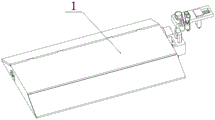
Fig. 1 is a schematic structural diagram of a bridge pavement cleaning device of the present invention.
Fig. 2 is a schematic top view of the bridge pavement cleaning apparatus according to the present invention.
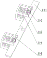
Fig. 3 is a schematic structural diagram of a part of the bridge road surface cleaning device of the invention.
Fig. 4 is a schematic structural diagram of a vehicle pedal 1 of the bridge road surface cleaning device of the invention.
Fig. 5 is a schematic structural view of a cleaning wheel 2 of the bridge pavement cleaning device of the invention.
Fig. 6 is a schematic structural diagram of a dust cover 2-1 of the bridge pavement cleaning device of the invention.
Fig. 7 is a schematic structural diagram of a rotating wheel 2-2 of the bridge pavement cleaning device of the invention.
Fig. 8 is a schematic structural diagram of a scraper 2-3 of the bridge pavement cleaning device.
Fig. 9 is a schematic structural diagram of the dust collector 2-4 of the bridge pavement cleaning device.
Fig. 10 is a schematic structural diagram of a collecting box 3 of the bridge pavement sweeping device of the invention.
Fig. 11 is a partial structural schematic view of the high-pressure water 4 of the bridge road surface cleaning device according to the present invention.
Fig. 12 is a schematic structural diagram of a moving device 5 of the bridge road surface cleaning device according to the present invention.
Fig. 13 is a schematic structural diagram of a moving device 5 of the bridge road surface cleaning device according to the present invention.
In the figure: a vehicle pedal 1; a main board 1-1; a front panel 1-2; a rear panel 1-3; 1-4 of air holes; spring seats 1-5; 1-6 of a chute; 1-7 of a horizontal chute; 1-8 of a bracket; a cleaning wheel 2; a dust cover 2-1; a connecting seat 2-1-1; 2-1-2 of a scraping groove; 2-1-3 of a spring column; 2-2 of a rotating wheel; cleaning a rotating wheel 2-2-1; a connector 2-2-2; 2-3 of a scraper plate; 2-3-1 of a transverse scraper; 2-3-2 parts of a buffer spring; 2-3-3 of a connecting plate; supplementing 2-3-4 of a spring; 2-3-5 parts of a spring frame; 2-4 of a dust collector; 2-4-1 of a dust hood; driving a motor 2-4-2; 2-4-3 of fan blades; 2-4-4 parts of a belt; 2-4-5 of a connecting pin; 2-4-6 parts of a screw; a collection box 3; 3-1 of a box body; a position-adaptive spring 3-2; 3-3 parts of a water roller; 3-4 parts of a drain pipe; 3-5 of a motor; 3-6 of a sliding ring; 3-7 of an upper slide block; 3-8 parts of a connecting block; 3-9 parts of a middle connecting block; 3-10 parts of a linking groove; 3-11 parts of a lower sliding block; 3-12 parts of a drainage pump; 4, high-pressure water; 4-1 of a water spraying cylinder; 4-2 of an adjusting wheel; 4-3 of a wiper blade; 4-4 parts of a limiting plate; pressing a spring 4-5; 4-6 of a trapezoidal sliding block; a moving device 5; comprises a link base 5-1; a chain connecting rod 5-2; 5-3 of a transverse plate; 5-4 of belt wheels; 5-5 parts of a first belt; 5-6 parts of a first motor; 5-7 parts of a second motor; chain 5-8; 5-9 parts of a first chain wheel; 5-10 parts of a second chain wheel; 5-11 parts of a motor chain wheel; 5-12 parts of clamping blocks; 5-13 parts of a clamping spring; 5-14 parts of driven wheel; 5-15 parts of a driving shaft; and 5-16 of driving wheels.
Detailed Description
The first embodiment is as follows:
the present embodiment is described below with reference to fig. 1, fig. 2, fig. 3, fig. 4, fig. 5, fig. 6, fig. 7, fig. 8, fig. 9, fig. 10, fig. 11, fig. 12, and fig. 13, and the present invention relates to a sampling device, and more specifically, to a bridge road surface cleaning device, which includes a vehicle pedal 1, a cleaning wheel 2, a collection box 3, high-pressure water 4, and a moving device 5, and the device can move along the road surface of the bridge, and can clean the road surface first, then clean with high-pressure water, and then discharge the cleaning water, and the device can not obstruct the vehicle from traveling.
The section of the vehicle pedal 1 is trapezoidal, the cleaning wheel 2 is positioned at the lower part of the vehicle pedal 1, the collecting box 3 is positioned at the middle part of the vehicle pedal 1, the high-pressure water 4 is positioned at the rear part of the vehicle pedal 1, and the moving device 5 is fixed at the side surface of the vehicle pedal 1.
The second embodiment is as follows:
the present embodiment is described below with reference to fig. 1, fig. 2, fig. 3, fig. 4, fig. 5, fig. 6, fig. 7, fig. 8, fig. 9, fig. 10, fig. 11, fig. 12, and fig. 13, and the present embodiment further describes the present embodiment, where the step board 1 includes a main board 1-1, a front board 1-2, a rear board 1-3, an air vent 1-4, a spring seat 1-5, a chute 1-6, a horizontal chute 1-7, and a bracket 1-8, an upper portion of the main board 1-1 is rectangular, a side surface of the main board 1-1 is trapezoidal, the front board 1-2 is located at a front portion of the main board 1-1, the rear board 1-3 is located at a rear portion of the main board 1-1, the air vent 1-4 is located at both sides of the main board 1-1, two spring seats 1-5 are provided, the spring seats 1-5 are, two sliding chutes 1-6 are provided, the sliding chutes 1-6 are positioned on the inner side of the main board 1-1, two transverse sliding chutes 1-7 are provided, the transverse sliding chutes 1-7 are positioned above the sliding chutes 1-6, two supports 1-8 are provided, and the supports 1-8 are positioned on the inner side of the main board 1-1.
The third concrete implementation mode:
the embodiment is described below with reference to fig. 1, fig. 2, fig. 3, fig. 4, fig. 5, fig. 6, fig. 7, fig. 8, fig. 9, fig. 10, fig. 11, fig. 12, fig. 13, and the embodiment further describes the embodiment, where the cleaning wheel 2 includes a dust cover 2-1, a rotating wheel 2-2, a scraper 2-3, and a dust collector 2-4, the dust cover 2-1 is fixed at the lower part of the main plate 1-1, the outer part of the dust cover 2-1 is square, the inner part of the dust cover 2-1 is cylindrical, the side surface of the dust cover 2-1 is provided with a rectangular opening, one end of the rotating wheel 2-2 is connected with the dust collector 2-4, the scraper 2-3 is in contact with the rotating wheel 2-2, and the dust collector 2-4 is fixed at the; the dust cover 2-1 comprises a connecting seat 2-1-1, scraping grooves 2-1-2 and spring columns 2-1-3, the connecting seat 2-1-1 is positioned at two ends of the dust cover 2-1, four through holes are processed on the connecting seat 2-1-1, the connecting seat 2-1-1 is connected with a main board 1-1 through screws, the scraping grooves 2-1-2 are positioned on the side surface of the dust cover 2-1, four spring columns 2-1-3 are arranged, and the spring columns 2-1-3 are connected with a scraping plate 2-3; the rotating wheel 2-2 comprises a cleaning rotating wheel 2-2-1 and a connector 2-2-2, the connectors 2-2-2 are arranged at two ends of the cleaning rotating wheel 2-2-1, a hexagonal prism groove is arranged at one end of the connector 2-2-2, and the connector 2-2-2 is connected with a dust collector 2-4; the scraping plates 2-3 comprise transverse scraping plates 2-3-1, buffer springs 2-3-2, connecting plates 2-3-3, supplementary springs 2-3-4 and spring frames 2-3-5, the transverse scraping plates 2-3-1 are cuboid, the transverse scraping plates 2-3-1 are in sliding fit with the scraping grooves 2-1-2, four buffer springs 2-3-2 are arranged, one ends of the buffer springs 2-3-2 are in contact with the dust cover 2-1, one ends of the buffer springs 2-3-2 are connected with the connecting plates 2-3-3, two connecting plates 2-3-3 are arranged, the connecting plates 2-3-3 are positioned at the same side of the transverse scraping plates 2-3-1, four supplementary springs 2-3-4 are arranged, one end of each supplementary spring 2-3-4 is in contact with the connecting plate 2-3-3, one end of each supplementary spring 2-3-4 is in contact with the spring frame 2-3-5, two spring frames 2-3-5 are arranged, and the spring frames 2-3-5 and the dust cover 2-1 are fixed together; the dust collector 2-4 comprises a dust hood 2-4-1, a driving motor 2-4-2, fan blades 2-4-3, a belt 2-4-4, a connecting pin 2-4-5 and a screw 2-4-6, one side of the dust hood 2-4-1 is connected with a main board 1-1 through screws, the dust hood 2-4-1 is communicated with air holes 1-4, the dust hood 2-4-1 is provided with three through holes, the driving motor 2-4-2 is fixed on one side of the dust hood 2-4-1, the number of the fan blades 2-4-3 is three, the fan blades 2-4-3 are in sliding fit with the dust hood 2-4-1, the belt 2-4-4 is connected with the fan blades 2-4-3, the belt 2-4-4 is connected with the connecting pin 2-4-5, one end of the connecting pin 2-4-5 is a hexagonal prism, the connecting pin 2-4-5 is connected with the rotating wheel 2-2, the middle part of the connecting pin 2-4-5 is in sliding fit with the dust hood 2-4-1, one end of the connecting pin 2-4-5 is provided with teeth, the screw rod 2-4-6 is fixed on a rotating shaft of the driving motor 2-4-2, and the screw rod 2-4-6 is connected with the connecting pin 2-4-5. Connecting a driving motor 2-4-3 into a circuit, starting the driving motor 2-4-3, enabling the driving motor 2-4-3 to rotate to drive a screw rod 2-4-6 to rotate, enabling the screw rod 2-4-6 to rotate to drive a connecting pin 2-4-5 to rotate, enabling the connecting pin 2-4-5 to drive a belt 2-4-4 to rotate by hand, enabling the belt 2-4-4 to drive a fan blade 2-4-3 to rotate, enabling the fan blade 2-4-3 to form negative pressure inside a dust cover 2-1, and removing dust; meanwhile, the connecting pin 2-4-5 rotates to drive the cleaning rotating wheel 2-2-1 to rotate, the cleaning rotating wheel 2-2-1 sweeps dust on the ground, and the dust is scraped off from the cleaning rotating wheel 2-2-1 under the action of the scraper 2-3; .
The fourth concrete implementation mode:
the present embodiment is described below with reference to fig. 1, fig. 2, fig. 3, fig. 4, fig. 5, fig. 6, fig. 7, fig. 8, fig. 9, fig. 10, fig. 11, fig. 12, and fig. 13, and the present embodiment further describes the present embodiment, where the collecting box 3 includes a box body 3-1, a position-adaptive spring 3-2, a water roller 3-3, a water discharge pipe 3-4, a motor 3-5, a sliding ring 3-6, an upper sliding block 3-7, a connecting block 3-8, a middle connecting block 3-9, a linking groove 3-10, a lower sliding block 3-11, and a water discharge pump 3-12, the box body 3-1 is a rectangular parallelepiped, one side of the box body 3-1 is opened, a chute is processed at the lower part of the opening side of the box body 3-1, two position-adaptive springs 3-2 are provided, the position-adaptive spring 3, the upper part of a proper position spring 3-2 is contacted with a main board 1-1, a water roller 3-3 is positioned at the opening side of a box body 3-1, the water roller 3-3 is in sliding fit with the box body 3-1, a groove is processed on the water roller 3-3, the lower part of a drain pipe 3-4 is connected with a drain pump 3-12, the upper part of a motor 3-5 is fixed at the lower part of the main board 1-1, a sliding ring 3-6 is fixed on a rotating shaft of the motor 3-5, an upper sliding block 3-7 is positioned inside the sliding ring 3-6, the upper sliding block 3-7 is in sliding fit with the sliding ring 3-6, one end of a connecting block 3-8 is connected with the upper sliding block 3-7, the lower part of the connecting block 3-8 is connected with a middle connecting block 3-9, the connecting groove 3-10 is fixed on the upper part of the box body 3-1, the lower part of the lower slider 3-11 is in sliding fit with the connecting groove 3-10, and the drainage pump 3-12 is positioned inside the box body 3-1. Starting the motor 3-5, rotating the motor 3-5 to drive the sliding ring 3-6 to rotate, rotating the sliding ring 3-6 to drive the upper slide block 3-7 to move, driving the connecting block 3-8 and the middle connecting block 3-9 to move by the upper slide block 3-7, driving the lower slide block 3-11 to move by the middle connecting block 3-9, realizing the up-and-down movement of the collecting box 3 under the action of the positioning spring 3-2, and in the working process, bringing the water into the collecting box 3 by the water roller 3-3 along with the contact with the ground under the action of friction force and discharging the water under the action of the drainage pump 3-12.
The fifth concrete implementation mode:
the embodiment is described below with reference to fig. 1, fig. 2, fig. 3, fig. 4, fig. 5, fig. 6, fig. 7, fig. 8, fig. 9, fig. 10, fig. 11, fig. 12, fig. 13, and the embodiment further describes the embodiment, where the high-pressure water 4 includes a water spraying cylinder 4-1, an adjusting wheel 4-2, a water scraping plate 4-3, a limit plate 4-4, a downward pressing spring 4-5, and a trapezoidal slider 4-6, the water spraying cylinder 4-1 is in sliding fit with the main plate 1-1, the adjusting wheel 4-2 is located at one end of the water spraying cylinder 4-1, the adjusting wheel 4-2 is in sliding fit with the main plate 1-1, the water scraping plate 4-3 is in sliding fit with the chute 1-6, the limit plate 4-4 is located at the upper portion of the water scraping plate 4-3, two cylinders are provided at the upper portion of the chute 1-6, two downward, the upper part of the lower pressure spring 4-5 is connected with the lower part of the trapezoidal sliding block 4-6, the lower part of the lower pressure spring 4-5 is connected with the limiting plate 4-4, the upper part of the trapezoidal sliding block 4-6 is trapezoidal, and the upper part of the trapezoidal sliding block 4-6 is in sliding fit with the transverse sliding groove 1-7. High-pressure water is introduced into the water spraying cylinder 4-1, the water is sprayed on the ground, and the water is kept at the lower part of the device under the action of the water scraping plate 4-3, so that the water is prevented from being dispersed outwards along with dust.
The sixth specific implementation mode:
referring to fig. 1, 2, 3, 4, 5, 6, 7, 8, 9, 10, 11, 12, 13, the embodiment will be further described, wherein the moving device 5 includes a link base 5-1, a link rod 5-2, a cross plate 5-3, a pulley 5-4, a belt one 5-5, a motor one 5-6, a motor two 5-7, a chain 5-8, a sprocket one 5-9, a sprocket two 5-10, a motor sprocket 5-11, a clamping block 5-12, a clamping spring 5-13, a driven pulley 5-14, a driving shaft 5-15, a driving pulley 5-16, the link base 5-1 is connected with the main plate 1-1, the lower portion of the link rod 5-2 is forked, the chain connecting rod 5-2 is connected with the chain connecting base 5-1, the upper part of the chain connecting rod 5-2 is in sliding fit with the transverse plate 5-3, the belt wheel 5-4 is fixed on the upper part of the chain connecting rod 5-2, one end of the belt I5-5 is connected with the belt wheel 5-4, one end of the belt I5-5 is connected with the motor I5-6, the motor I5-6 is fixed on one side of the transverse plate 5-3, the motor II 5-7 is fixed on one side of the transverse plate 5-3, one end of the chain 5-8 is connected with the chain wheel II 5-10, the chain 5-8 is connected with the chain wheel I5-9, the chain 5-8 is connected with the motor chain wheel 5-11, the clamping block 5-12 is in sliding fit with the transverse plate 5-3, one, one end of a clamping spring 5-13 is connected with the transverse plate 5-3, a driven wheel 5-14 is connected with a clamping block 5-12, the upper part of a driving shaft 5-15 is in sliding fit with the transverse plate 5-3, the upper part of the driving shaft 5-15 is connected with a chain wheel I5-9, and the upper part of the driving shaft 5-15 is connected with a chain wheel I5-9; the two chain wheels 5-10 are connected, two driving shafts 5-15 are provided, two driving wheels 5-16 are provided, and the driving wheels 5-16 are fixed on the driving shafts 5-15. The device is placed on the road surface of a bridge, a pedal 1 is placed on the bridge floor, a moving device 5 is placed on a fence, a motor II 5-7 is connected to a circuit, the motor II 5-7 is started, the motor 5-7 drives a motor chain wheel 5-11, the motor chain wheel 5-11 drives a chain wheel I5-9 and a chain wheel II 5-10 to rotate, the chain wheel I5-9 and the chain wheel II 5-10 drive a lower driving shaft 5-15 to rotate, the driving shaft 5-15 drives a driving wheel 5-16 to rotate, the driving wheel 5-16 and the fence are in friction driving device movement, and under the action of a clamping spring 5-13, a clamping block 5-12 drives a driven wheel 5-14 to be tightly pressed on the other side of the fence; and simultaneously, starting the motor I5-6, driving the belt I5-5 to rotate by the rotation of the motor I5-6, driving the belt I5-5 to rotate the belt wheel 5-4, and driving the belt wheel 5-4 to drive the chain connecting rod 5-2 to rotate, thereby realizing the folding and unfolding of the device without influencing the road when not in use.
The seventh embodiment:
the present embodiment will be described below with reference to fig. 1, 2, 3, 4, 5, 6, 7, 8, 9, 10, 11, 12, and 13, and the present embodiment further describes the first embodiment in which the material of the step panel 1 is an aluminum alloy.
The specific implementation mode is eight:
the present embodiment will be described below with reference to fig. 1, 2, 3, 4, 5, 6, 7, 8, 9, 10, 11, 12, and 13, and the present embodiment further describes that the lower portion of the dust cover 2-1 is horizontal to the main plate 1-1.
The specific implementation method nine:
the present embodiment will be described below with reference to fig. 1, 2, 3, 4, 5, 6, 7, 8, 9, 10, 11, 12, and 13, and the present embodiment will further describe a first embodiment in which the wiper blade 4-3 is made of rubber.
The working principle of the device is as follows: 1, motion principle: the device is placed on the road surface of a bridge, a pedal 1 is placed on the bridge floor, a moving device 5 is placed on a fence, a motor II 5-7 is connected to a circuit, the motor II 5-7 is started, the motor 5-7 drives a motor chain wheel 5-11, the motor chain wheel 5-11 drives a chain wheel I5-9 and a chain wheel II 5-10 to rotate, the chain wheel I5-9 and the chain wheel II 5-10 drive a lower driving shaft 5-15 to rotate, the driving shaft 5-15 drives a driving wheel 5-16 to rotate, the driving wheel 5-16 and the fence are in friction driving device movement, and under the action of a clamping spring 5-13, a clamping block 5-12 drives a driven wheel 5-14 to be tightly pressed on the other side of the fence; and simultaneously, starting the motor I5-6, driving the belt I5-5 to rotate by the rotation of the motor I5-6, driving the belt I5-5 to rotate the belt wheel 5-4, and driving the belt wheel 5-4 to drive the chain connecting rod 5-2 to rotate, thereby realizing the folding and unfolding of the device without influencing the road when not in use.
2, the working principle is as follows: connecting a driving motor 2-4-3 into a circuit, starting the driving motor 2-4-3, enabling the driving motor 2-4-3 to rotate to drive a screw rod 2-4-6 to rotate, enabling the screw rod 2-4-6 to rotate to drive a connecting pin 2-4-5 to rotate, enabling the connecting pin 2-4-5 to drive a belt 2-4-4 to rotate by hand, enabling the belt 2-4-4 to drive a fan blade 2-4-3 to rotate, enabling the fan blade 2-4-3 to form negative pressure inside a dust cover 2-1, and removing dust; meanwhile, the connecting pin 2-4-5 rotates to drive the cleaning rotating wheel 2-2-1 to rotate, the cleaning rotating wheel 2-2-1 sweeps dust on the ground, and the dust is scraped off from the cleaning rotating wheel 2-2-1 under the action of the scraper 2-3;
3, starting a motor 3-5, rotating the motor 3-5 to drive a sliding ring 3-6 to rotate, rotating the sliding ring 3-6 to drive an upper slide block 3-7 to move, driving a connecting block 3-8 and an intermediate connecting block 3-9 to move by the upper slide block 3-7, driving a lower slide block 3-11 to move by the intermediate connecting block 3-9, realizing the up-and-down movement of the collecting box 3 under the action of an adaptive spring 3-2, and in the working process, bringing water into the collecting box 3 by the water stick 3-3 under the action of friction along with the contact with the ground, and discharging the water under the action of a drainage pump 3-12;
4, high-pressure water is fed into the water spraying cylinder 4-1, the water is sprayed on the ground, and the water is kept at the lower part of the device under the action of the water scraping plate 4-3, so that the water is prevented from being dispersed outwards along with dust.
It is to be understood that the above description is not intended to limit the present invention, and the present invention is not limited to the above examples, and that various changes, modifications, additions and substitutions which are within the spirit and scope of the present invention and which may be made by those skilled in the art are also within the scope of the present invention.
Claims (9)
1. The utility model provides a bridge road surface cleaning device, includes car footboard (1), cleaning wheel (2), collecting box (3), high pressure water (4), mobile device (5), its characterized in that: the cross section of the car pedal (1) is trapezoidal, the cleaning wheel (2) is positioned at the lower part of the car pedal (1), the collecting box (3) is positioned at the middle part of the car pedal (1), the high-pressure water (4) is positioned at the rear part of the car pedal (1), and the moving device (5) is fixed on the side surface of the car pedal (1).
2. A bridge road surface sweeping device according to claim 1, characterized in that: the vehicle pedal (1) comprises a main board (1-1), a front board (1-2), a rear board (1-3), air holes (1-4), spring seats (1-5), sliding chutes (1-6), transverse sliding chutes (1-7) and supports (1-8), wherein the upper part of the main board (1-1) is rectangular, the side surface of the main board (1-1) is trapezoidal, the front board (1-2) is positioned at the front part of the main board (1-1), the rear board (1-3) is positioned at the rear part of the main board (1-1), the air holes (1-4) are positioned at two sides of the main board (1-1), two spring seats (1-5) are arranged, the spring seats (1-5) are fixed at the inner lower part of the main board (1-1), two sliding chutes (1-6) are arranged, the sliding chutes (1-6) are positioned at the inner side of the main board (1-1), two transverse sliding chutes (1-7) are arranged, the transverse sliding chutes (1-7) are positioned above the sliding chutes (1-6), two supports (1-8) are arranged, and the supports (1-8) are positioned on the inner side of the main board (1-1).
3. A bridge road surface sweeping device according to claim 1, characterized in that: the cleaning wheel (2) comprises a dust cover (2-1), a rotating wheel (2-2), a scraping plate (2-3) and a dust collector (2-4), the dust cover (2-1) is fixed on the lower portion of a main board (1-1), the outer portion of the dust cover (2-1) is square, the inner portion of the dust cover (2-1) is cylindrical, a rectangular opening is formed in the side face of the dust cover (2-1), one end of the rotating wheel (2-2) is connected with the dust collector (2-4), the scraping plate (2-3) is in contact with the rotating wheel (2-2), and the dust collector (2-4) is fixed on the outer side of the main board (1-1); the dust cover (2-1) comprises connecting seats (2-1-1), scraping grooves (2-1-2) and spring columns (2-1-3), the connecting seats (2-1-1) are located at two ends of the dust cover (2-1), four through holes are processed in the connecting seats (2-1-1), the connecting seats (2-1-1) are connected with a main board (1-1) through screws, the scraping grooves (2-1-2) are located on the side face of the dust cover (2-1), four spring columns (2-1-3) are arranged, and the spring columns (2-1-3) are connected with scraping plates (2-3); the rotating wheel (2-2) comprises a cleaning rotating wheel (2-2-1) and a connector (2-2-2), the connectors (2-2-2) are arranged at two ends of the cleaning rotating wheel (2-2-1), a hexagonal prism groove is arranged at one end of the connector (2-2-2), and the connector (2-2-2) is connected with a dust collector (2-4); the scraping plates (2-3) comprise transverse scraping plates (2-3-1), buffer springs (2-3-2), connecting plates (2-3-3), supplementary springs (2-3-4) and spring frames (2-3-5), the transverse scraping plates (2-3-1) are cuboid, the transverse scraping plates (2-3-1) are in sliding fit with the scraping grooves (2-1-2), four buffer springs (2-3-2) are arranged, one ends of the buffer springs (2-3-2) are in contact with the dust cover (2-1), one ends of the buffer springs (2-3-2) are connected with the connecting plates (2-3-3), two connecting plates (2-3-3) are arranged, and the connecting plates (2-3-3) are located on the same side of the transverse scraping plates (2-3-1), four supplementary springs (2-3-4) are arranged, one end of each supplementary spring (2-3-4) is in contact with the connecting plate (2-3-3), one end of each supplementary spring (2-3-4) is in contact with the spring frame (2-3-5), two spring frames (2-3-5) are arranged, and the spring frames (2-3-5) and the dust cover (2-1) are fixed together; the dust collector (2-4) comprises a dust hood (2-4-1), a driving motor (2-4-2), fan blades (2-4-3), a belt (2-4-4), a connecting pin (2-4-5) and a screw rod (2-4-6), one side of the dust hood (2-4-1) is connected with the main board (1-1) through screws, the dust hood (2-4-1) is communicated with the air holes (1-4), the dust hood (2-4-1) is provided with three through holes, the driving motor (2-4-2) is fixed on one side of the dust hood (2-4-1), the number of the fan blades (2-4-3) is three, the fan blades (2-4-3) are in sliding fit with the dust hood (2-4-1), the belt (2-4-4) is connected with the fan blade (2-4-3), the belt (2-4-4) is connected with the connecting pin (2-4-5), one end of the connecting pin (2-4-5) is a hexagonal prism, the connecting pin (2-4-5) is connected with the rotating wheel (2-2), the middle of the connecting pin (2-4-5) is in sliding fit with the dust hood (2-4-1), one end of the connecting pin (2-4-5) is provided with teeth, the screw rod (2-4-6) is fixed on a rotating shaft of the driving motor (2-4-2), and the screw rod (2-4-6) is connected with the connecting pin (2-4-5).
4. A bridge road surface sweeping device according to claim 1, characterized in that: the collecting box (3) comprises a box body (3-1), a proper position spring (3-2), water rollers (3-3), drain pipes (3-4), a motor (3-5), a sliding ring (3-6), an upper sliding block (3-7), a connecting block (3-8), a middle connecting block (3-9), a linking groove (3-10), a lower sliding block (3-11) and a drain pump (3-12), wherein the box body (3-1) is a cuboid, one side of the box body (3-1) is provided with an opening, the lower part of the opening side of the box body (3-1) is provided with a chute, the proper position springs (3-2) are arranged in two, the proper position spring (3-2) is sleeved on a spring seat (1-5), the upper part of the proper position spring (3-2) is contacted with a main board (1-1), the water roller (3-3) is positioned at the opening side of the box body (3-1), the water roller (3-3) is in sliding fit with the box body (3-1), the water roller (3-3) is provided with a groove, the lower part of the drain pipe (3-4) is connected with the drain pump (3-12), the upper part of the motor (3-5) is fixed at the lower part of the main board (1-1), the sliding ring (3-6) is fixed on the rotating shaft of the motor (3-5), the upper sliding block (3-7) is positioned inside the sliding ring (3-6), the upper sliding block (3-7) is in sliding fit with the sliding ring (3-6), one end of the connecting block (3-8) is connected with the upper sliding block (3-7), the lower part of the connecting block (3-8) is connected with the middle connecting block (3-9), the lower part of the middle connecting block (3-9) is connected with the lower sliding, the linking groove (3-10) is fixed at the upper part of the box body (3-1), the lower part of the lower slide block (3-11) is in sliding fit with the linking groove (3-10), and the drainage pump (3-12) is positioned inside the box body (3-1).
5. A bridge road surface sweeping device according to claim 1, characterized in that: the high-pressure water (4) comprises a water spraying cylinder (4-1), an adjusting wheel (4-2), a water scraping plate (4-3), a limiting plate (4-4), a pressing spring (4-5) and a trapezoidal sliding block (4-6), the water spraying cylinder (4-1) is in sliding fit with a main plate (1-1), the adjusting wheel (4-2) is positioned at one end of the water spraying cylinder (4-1), the adjusting wheel (4-2) is in sliding fit with the main plate (1-1), the water scraping plate (4-3) is in sliding fit with a sliding groove (1-6), the limiting plate (4-4) is positioned at the upper part of the water scraping plate (4-3), two cylinders are arranged at the upper part of the sliding groove (1-6), two pressing springs (4-5) are arranged, the upper part of the pressing springs (4-5) is connected with the lower part of the trapezoidal sliding block (4-6), the lower part of the pressing spring (4-5) is connected with the limiting plate (4-4), the upper part of the trapezoidal sliding block (4-6) is trapezoidal, and the upper part of the trapezoidal sliding block (4-6) is in sliding fit with the transverse sliding chute (1-7).
6. A bridge road surface sweeping device according to claim 1, characterized in that: the moving device (5) comprises a linking base (5-1), a linking rod (5-2), a transverse plate (5-3), a belt wheel (5-4), a belt I (5-5), a motor I (5-6), a motor II (5-7), a chain (5-8), a chain wheel I (5-9), a chain wheel II (5-10), a motor chain wheel (5-11), a clamping block (5-12), a clamping spring (5-13), a driven wheel (5-14), a driving shaft (5-15) and a driving wheel (5-16), wherein the linking base (5-1) is connected with the main board (1-1), the lower part of the linking rod (5-2) is forked, and the linking rod (5-2) is connected with the linking base (5-1), the upper part of a chain connecting rod (5-2) is in sliding fit with a transverse plate (5-3), a belt wheel (5-4) is fixed on the upper part of the chain connecting rod (5-2), one end of a belt I (5-5) is connected with the belt wheel (5-4), one end of the belt I (5-5) is connected with a motor I (5-6), the motor I (5-6) is fixed on one side of the transverse plate (5-3), a motor II (5-7) is fixed on one side of the transverse plate (5-3), one end of a chain (5-8) is connected with a chain wheel II (5-10), the chain (5-8) is connected with the chain wheel I (5-9), the chain (5-8) is connected with a motor chain wheel (5-11), a clamping block (5-12) is in sliding fit with the transverse plate (5-3), one end of a clamping spring (5-13) is connected with the clamping block (5-, one end of a clamping spring (5-13) is connected with the transverse plate (5-3), a driven wheel (5-14) is connected with a clamping block (5-12), the upper part of a driving shaft (5-15) is in sliding fit with the transverse plate (5-3), the upper part of the driving shaft (5-15) is connected with a first chain wheel (5-9), and the upper part of the driving shaft (5-15) is connected with a second chain wheel (5-9); the two chain wheels (5-10) are connected, two driving shafts (5-15) are provided, two driving wheels (5-16) are provided, and the driving wheels (5-16) are fixed on the driving shafts (5-15).
7. A bridge road surface sweeping device according to claim 1, characterized in that: the automobile pedal (1) is made of aluminum alloy.
8. A bridge road surface sweeping device according to claim 1, characterized in that: the lower part of the dust cover (2-1) is horizontal to the main board (1-1).
9. A bridge road surface sweeping device according to claim 1, characterized in that: the wiper blade (4-3) is made of rubber.
Priority Applications (1)
| Application Number | Priority Date | Filing Date | Title |
|---|---|---|---|
| CN202010358928.2A CN111395236A (en) | 2020-04-29 | 2020-04-29 | Bridge road surface cleaning device |
Applications Claiming Priority (1)
| Application Number | Priority Date | Filing Date | Title |
|---|---|---|---|
| CN202010358928.2A CN111395236A (en) | 2020-04-29 | 2020-04-29 | Bridge road surface cleaning device |
Publications (1)
| Publication Number | Publication Date |
|---|---|
| CN111395236A true CN111395236A (en) | 2020-07-10 |
Family
ID=71426787
Family Applications (1)
| Application Number | Title | Priority Date | Filing Date |
|---|---|---|---|
| CN202010358928.2A Withdrawn CN111395236A (en) | 2020-04-29 | 2020-04-29 | Bridge road surface cleaning device |
Country Status (1)
| Country | Link |
|---|---|
| CN (1) | CN111395236A (en) |
Cited By (1)
| Publication number | Priority date | Publication date | Assignee | Title |
|---|---|---|---|---|
| CN112030860A (en) * | 2020-09-09 | 2020-12-04 | 雷成平 | Road surface deicing machine |
Citations (12)
| Publication number | Priority date | Publication date | Assignee | Title |
|---|---|---|---|---|
| US5542148A (en) * | 1991-07-03 | 1996-08-06 | Tymco, Inc. | Broom assisted pick-up head |
| KR100766315B1 (en) * | 2007-03-13 | 2007-10-12 | 주식회사 태경이엔지 | Sidewalk Water Cleaning Equipment |
| CN107313376A (en) * | 2017-07-13 | 2017-11-03 | 安徽南博机器人有限公司 | A kind of dust suction, wash ground, drying integral machine |
| CN207244513U (en) * | 2017-07-20 | 2018-04-17 | 孙大亮 | One kind cleaning car |
| CN207405550U (en) * | 2017-11-13 | 2018-05-25 | 山东科技大学 | It is a kind of to cycle the Multifunction cleaning vehicle to mop floor |
| EP3375937A1 (en) * | 2017-03-17 | 2018-09-19 | Stock Sweepers Limited | Suction-type cleaning vehicle |
| CN109098131A (en) * | 2018-09-22 | 2018-12-28 | 江苏悦达专用车有限公司 | A kind of sucker |
| CN209066360U (en) * | 2018-09-18 | 2019-07-05 | 安徽爱瑞特新能源专用汽车股份有限公司 | A kind of washing and brushing device for scrubbing soil pick-up one |
| CN110403537A (en) * | 2019-08-06 | 2019-11-05 | 山东浩睿智能科技有限公司 | Multi-functional clean ground machine |
| CN110652258A (en) * | 2019-11-06 | 2020-01-07 | 宁波福瑞电子科技有限公司 | A floor cleaning device |
| CN110792058A (en) * | 2019-10-25 | 2020-02-14 | 深圳市雄鹰清洁服务有限公司 | A device for high-pressure cleaning of road surfaces |
| CN110915459A (en) * | 2019-11-29 | 2020-03-27 | 宁波昂霖智能装备有限公司 | Cleaning robot |
-
2020
- 2020-04-29 CN CN202010358928.2A patent/CN111395236A/en not_active Withdrawn
Patent Citations (12)
| Publication number | Priority date | Publication date | Assignee | Title |
|---|---|---|---|---|
| US5542148A (en) * | 1991-07-03 | 1996-08-06 | Tymco, Inc. | Broom assisted pick-up head |
| KR100766315B1 (en) * | 2007-03-13 | 2007-10-12 | 주식회사 태경이엔지 | Sidewalk Water Cleaning Equipment |
| EP3375937A1 (en) * | 2017-03-17 | 2018-09-19 | Stock Sweepers Limited | Suction-type cleaning vehicle |
| CN107313376A (en) * | 2017-07-13 | 2017-11-03 | 安徽南博机器人有限公司 | A kind of dust suction, wash ground, drying integral machine |
| CN207244513U (en) * | 2017-07-20 | 2018-04-17 | 孙大亮 | One kind cleaning car |
| CN207405550U (en) * | 2017-11-13 | 2018-05-25 | 山东科技大学 | It is a kind of to cycle the Multifunction cleaning vehicle to mop floor |
| CN209066360U (en) * | 2018-09-18 | 2019-07-05 | 安徽爱瑞特新能源专用汽车股份有限公司 | A kind of washing and brushing device for scrubbing soil pick-up one |
| CN109098131A (en) * | 2018-09-22 | 2018-12-28 | 江苏悦达专用车有限公司 | A kind of sucker |
| CN110403537A (en) * | 2019-08-06 | 2019-11-05 | 山东浩睿智能科技有限公司 | Multi-functional clean ground machine |
| CN110792058A (en) * | 2019-10-25 | 2020-02-14 | 深圳市雄鹰清洁服务有限公司 | A device for high-pressure cleaning of road surfaces |
| CN110652258A (en) * | 2019-11-06 | 2020-01-07 | 宁波福瑞电子科技有限公司 | A floor cleaning device |
| CN110915459A (en) * | 2019-11-29 | 2020-03-27 | 宁波昂霖智能装备有限公司 | Cleaning robot |
Cited By (1)
| Publication number | Priority date | Publication date | Assignee | Title |
|---|---|---|---|---|
| CN112030860A (en) * | 2020-09-09 | 2020-12-04 | 雷成平 | Road surface deicing machine |
Similar Documents
| Publication | Publication Date | Title |
|---|---|---|
| CN102162221B (en) | A cleaning maintenance vehicle using in a track | |
| CN202139568U (en) | Cleaning and maintaining car for tracks | |
| CN219104772U (en) | Road disease detection device | |
| CN222044049U (en) | High-efficiency road cleaning device | |
| CN202466496U (en) | Roadway grease dirt cleaner | |
| CN109024410A (en) | A kind of mini motor sweeper | |
| CN210529584U (en) | Road and bridge belt cleaning device | |
| CN2331697Y (en) | Spray type scavenging machine for pavement | |
| CN209099261U (en) | Mini motor sweeper | |
| CN113250132A (en) | Ice layer removing equipment for municipal roads | |
| CN218322265U (en) | Road marking removing equipment | |
| CN215888058U (en) | Rear sweeping and rolling lifting mechanism for road sweeper | |
| CN220846946U (en) | Flattening device for asphalt road maintenance | |
| CN223202252U (en) | A suction port device suitable for large dust removal and haze reduction vehicles | |
| CN203580928U (en) | Sweeper brake device | |
| CN2223753Y (en) | Road cleaning vehicle | |
| CN2718051Y (en) | High-speed dust-sucking road surface cleaning machine | |
| CN207079526U (en) | A kind of vehicular road cleaning and dust arrester | |
| CN216899647U (en) | High-precision side-slipping inspection bench for vehicle detection | |
| CN217517450U (en) | Automatic cleaning equipment of municipal administration regeneration asphalt concrete hollow road pavement | |
| CN221501672U (en) | Thin layer surface maintenance device | |
| CN202626804U (en) | Road marked line polishing and washing remover | |
| CN220450621U (en) | Vehicle-mounted laser scanning device | |
| CN219137335U (en) | Road surface cleaning device of road surface maintenance vehicle | |
| CN219586635U (en) | Barrow type road laser cleaning machine |
Legal Events
| Date | Code | Title | Description |
|---|---|---|---|
| PB01 | Publication | ||
| PB01 | Publication | ||
| SE01 | Entry into force of request for substantive examination | ||
| SE01 | Entry into force of request for substantive examination | ||
| WW01 | Invention patent application withdrawn after publication |
Application publication date: 20200710 |
|
| WW01 | Invention patent application withdrawn after publication |