CN111390390A - Laser-resistance hybrid welding device for car seat recliner fixing seat - Google Patents
Laser-resistance hybrid welding device for car seat recliner fixing seat Download PDFInfo
- Publication number
- CN111390390A CN111390390A CN202010241266.0A CN202010241266A CN111390390A CN 111390390 A CN111390390 A CN 111390390A CN 202010241266 A CN202010241266 A CN 202010241266A CN 111390390 A CN111390390 A CN 111390390A
- Authority
- CN
- China
- Prior art keywords
- assembly
- welding
- shaped
- laser
- plate
- Prior art date
- Legal status (The legal status is an assumption and is not a legal conclusion. Google has not performed a legal analysis and makes no representation as to the accuracy of the status listed.)
- Granted
Links
Images


Classifications
-
- B—PERFORMING OPERATIONS; TRANSPORTING
- B23—MACHINE TOOLS; METAL-WORKING NOT OTHERWISE PROVIDED FOR
- B23K—SOLDERING OR UNSOLDERING; WELDING; CLADDING OR PLATING BY SOLDERING OR WELDING; CUTTING BY APPLYING HEAT LOCALLY, e.g. FLAME CUTTING; WORKING BY LASER BEAM
- B23K26/00—Working by laser beam, e.g. welding, cutting or boring
- B23K26/346—Working by laser beam, e.g. welding, cutting or boring in combination with welding or cutting covered by groups B23K5/00 - B23K25/00, e.g. in combination with resistance welding
-
- B—PERFORMING OPERATIONS; TRANSPORTING
- B23—MACHINE TOOLS; METAL-WORKING NOT OTHERWISE PROVIDED FOR
- B23K—SOLDERING OR UNSOLDERING; WELDING; CLADDING OR PLATING BY SOLDERING OR WELDING; CUTTING BY APPLYING HEAT LOCALLY, e.g. FLAME CUTTING; WORKING BY LASER BEAM
- B23K26/00—Working by laser beam, e.g. welding, cutting or boring
- B23K26/70—Auxiliary operations or equipment
- B23K26/702—Auxiliary equipment
-
- G—PHYSICS
- G01—MEASURING; TESTING
- G01N—INVESTIGATING OR ANALYSING MATERIALS BY DETERMINING THEIR CHEMICAL OR PHYSICAL PROPERTIES
- G01N21/00—Investigating or analysing materials by the use of optical means, i.e. using sub-millimetre waves, infrared, visible or ultraviolet light
- G01N21/84—Systems specially adapted for particular applications
Landscapes
- Engineering & Computer Science (AREA)
- Physics & Mathematics (AREA)
- Mechanical Engineering (AREA)
- Plasma & Fusion (AREA)
- Optics & Photonics (AREA)
- Analytical Chemistry (AREA)
- General Health & Medical Sciences (AREA)
- General Physics & Mathematics (AREA)
- Immunology (AREA)
- Pathology (AREA)
- Biochemistry (AREA)
- Chemical & Material Sciences (AREA)
- Life Sciences & Earth Sciences (AREA)
- Health & Medical Sciences (AREA)
- Automatic Assembly (AREA)
- Laser Beam Processing (AREA)
Abstract
本发明提供了一种汽车座椅调角器固定座的激光‑电阻复合焊接装置,包括异形不锈钢板上料组件、高强度螺栓上料组件、检测组件、激光点焊组件、激光‑电阻复合焊接组件、下料组件、凸轮分割器组件、工件和机架;所述激光点焊组件包括角座、点焊安装架、M向电动模组、N向电动模组、Z向电动模组和激光点焊焊接头。所述激光‑电阻复合焊接组件包括机器人安装架、六轴机器人、激光焊接头、CCD工业相机和电阻焊组件。本发明根据汽车座椅调角器固定座的结构特征及装配工序要求设计,涵盖了自动化上下料、定位光电检测、自动化点焊、自动化激光‑电阻复合焊、自动化下料等工序,可实现高效率、高精度的汽车座椅调角器固定座激光‑电阻复合焊接封装。
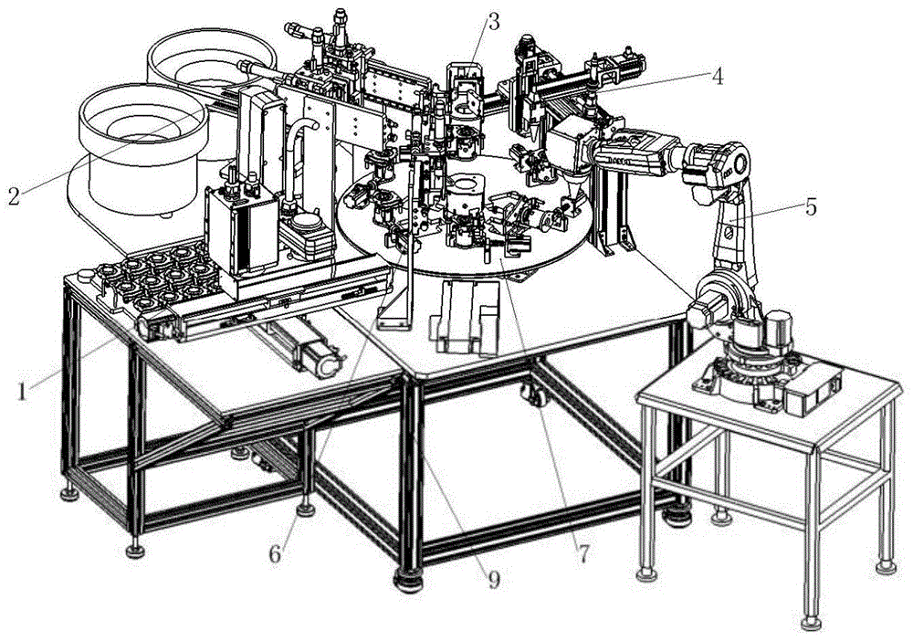
The invention provides a laser-resistance composite welding device for a fixing seat of a car seat recliner, including a special-shaped stainless steel plate feeding assembly, a high-strength bolt feeding assembly, a detection assembly, a laser spot welding assembly, and a laser-resistance composite welding. Assembly, blanking assembly, cam divider assembly, workpiece and frame; the laser spot welding assembly includes corner seat, spot welding mounting frame, M-direction electric module, N-direction electric module, Z-direction electric module and laser Spot welded joints. The laser-resistance hybrid welding assembly includes a robot mounting frame, a six-axis robot, a laser welding head, a CCD industrial camera, and a resistance welding assembly. The invention is designed according to the structural features of the seat of the car seat recliner and the requirements of the assembly process, and covers the processes of automatic loading and unloading, positioning photoelectric detection, automatic spot welding, automatic laser-resistance composite welding, automatic cutting and other processes, and can achieve high High-efficiency, high-precision laser-resistance hybrid welding package for car seat recliner mounts.
Description
技术领域technical field
本发明属于激光加工领域,具体涉及一种汽车座椅调角器固定座的激光-电阻复合焊接装置。The invention belongs to the field of laser processing, and in particular relates to a laser-resistance composite welding device for a fixing seat of a recliner of an automobile seat.
背景技术Background technique
随着汽车行业的快速发展,对汽车座椅的安全性和舒适性的要求越来越高,调角器固定座作为连接汽车座椅底座与靠背的关键性承力部件,不仅为乘车人员提供良好的乘车体验,而且其焊接质量的好坏直接影响乘车人员的人身安全。目前,汽车座椅调角器固定座焊接主要以CO2气保焊、电阻焊及激光焊接为主。首先,CO2气保焊虽然焊接成本低,焊接工艺成熟,但是焊接造成的飞溅与虚焊导致焊缝强度较低;其次,电阻焊虽然具有焊接效率高,焊接热影响区小,焊接变形小等优点,但是难以通过无损检测来准确判断焊点的质量,另外焊件尺寸、形状及厚度等因素使得电阻焊受限;最后,激光焊接具有聚焦光斑小,功率密度高、焊缝窄,可加工材料广泛等优点,但是对于一些高反射性及高导热性材料如铝、铜及其合金等,对激光的吸收率低,使得激光焊接的转化效率较低(约为5%~30%)。With the rapid development of the automobile industry, the requirements for the safety and comfort of car seats are getting higher and higher. Provide a good riding experience, and the quality of its welding directly affects the personal safety of passengers. At present, the welding of car seat recliner fixing seat is mainly based on CO 2 gas shielded welding, resistance welding and laser welding. First of all, although CO 2 gas shielded welding has low welding cost and mature welding process, the spatter and virtual welding caused by welding lead to low weld strength; secondly, although resistance welding has high welding efficiency, small welding heat affected zone, and small welding deformation However, it is difficult to accurately judge the quality of solder joints through non-destructive testing. In addition, factors such as the size, shape and thickness of the weldment make resistance welding limited. Finally, laser welding has the advantages of small focused spot, high power density, and narrow weld seam. However, for some highly reflective and high thermal conductivity materials such as aluminum, copper and their alloys, the absorption rate of laser light is low, which makes the conversion efficiency of laser welding low (about 5% to 30%) .
发明内容SUMMARY OF THE INVENTION
本发明针对上述现有技术的不足,提供了一种汽车座椅调角器固定座的激光-电阻复合焊接装置。Aiming at the above-mentioned deficiencies of the prior art, the present invention provides a laser-resistance composite welding device for the fixing seat of the recliner of an automobile seat.
本发明是通过如下技术方案实现的:The present invention is achieved through the following technical solutions:
一种汽车座椅调角器固定座的激光-电阻复合焊接装置,包括异形不锈钢板上料组件、高强度螺栓上料组件、检测组件、激光点焊组件、激光-电阻复合焊接组件、下料组件、凸轮分割器组件、工件和机架;A laser-resistance composite welding device for a fixed seat of a car seat recliner, comprising a special-shaped stainless steel plate feeding component, a high-strength bolt feeding component, a detection component, a laser spot welding component, a laser-resistance composite welding component, and a blanking component. assemblies, cam divider assemblies, workpieces and frames;
所述异形不锈钢板上料组件包括型材架、Y向电动模组、X向电动模组、上料机器人、真空吸盘组件和异形不锈钢板码垛盘;所述X向电动模组与Y向电动模组组成二维移动平台,上料机器人设置在Y向电动模组上;所述真空吸盘组件包括真空吸盘和真空吸盘安装架,真空吸盘共三组,固定安装在真空吸盘安装架对应的三个通孔处;所述异形不锈钢板码垛盘包括定位盘、圆形导向凸台和把手,圆形导向凸台为四个,均设置在型材架上,四个圆形导向凸台的圆心连线构成一长方形;异形不锈钢板以六行三列的方式均匀码放在定位盘上,定位盘四个顶角为内凹四分之一圆形,与设置在型材架上的四个圆形导向凸台的外圆凸边相配,定位盘两端对称设置有把手;The special-shaped stainless steel plate feeding assembly includes a profile frame, a Y-direction electric module, an X-direction electric module, a feeding robot, a vacuum suction cup assembly and a special-shaped stainless steel plate pallet; the X-direction electric module and the Y-direction electric module are The module forms a two-dimensional mobile platform, and the feeding robot is arranged on the Y-direction electric module; the vacuum suction cup assembly includes a vacuum suction cup and a vacuum suction cup mounting frame. There are three groups of vacuum suction cups, which are fixedly installed on the corresponding three vacuum suction cup mounting frames. The special-shaped stainless steel plate pallet includes a positioning plate, a circular guide boss and a handle. There are four circular guide bosses, all of which are arranged on the profile frame. The center of the four circular guide bosses The connecting line forms a rectangle; the special-shaped stainless steel plates are evenly placed on the positioning plate in six rows and three columns, and the four top corners of the positioning plate are concave quarter circles, which are in line with the four circles set on the profile frame. The outer circular convex edge of the guide boss is matched, and the two ends of the positioning plate are symmetrically provided with handles;
所述高强度螺栓上料组件包括长螺栓上料组件和短螺栓上料组件;所述长螺栓上料组件和短螺栓上料组件结构相同,左右对称的安装在机架上;所述长螺栓上料组件包括振动盘、直振器、输料道、第一L形安装架、Z形手指、气爪、Z向移动装置和X向移动装置;所述长螺栓依次通过振动盘、直振器、输料道传输至输料道的末端;所述Z形手指为一对,对称设置在气爪上,气爪安装在Z向移动装置上;所述Z向移动装置和X向移动装置构成二维移动装置,并安装在第一L形安装架上;The high-strength bolt feeding assembly includes a long bolt feeding assembly and a short bolt feeding assembly; the long bolt feeding assembly and the short bolt feeding assembly have the same structure and are installed on the frame symmetrically; the long bolt feeding assembly has the same structure as the short bolt feeding assembly. The feeding assembly includes a vibrating plate, a straight vibrator, a feeding channel, a first L-shaped mounting frame, a Z-shaped finger, an air gripper, a Z-direction moving device and an X-direction moving device; the long bolts pass through the vibrating plate, the direct vibration The Z-shaped fingers are a pair, which are symmetrically arranged on the air gripper, and the air gripper is installed on the Z-direction moving device; the Z-direction moving device and the X-direction moving device A two-dimensional mobile device is formed and installed on the first L-shaped mounting frame;
所述检测组件包括第二L形安装架、升降气缸、升降气缸安装板、L形转接板、定位卡件、升降滑板、导轨组件、限位开关、挡板、光电检测开关和光电检测开关安装板;所述升降气缸通过升降气缸安装板安装在第二L形安装架侧面,L形转接板呈L形,一端与升降气缸的活塞杆同轴装配,另一端与定位卡件连接,定位卡件设置在升降滑板一侧,在升降气缸驱动下升降滑板沿着导轨组件上下移动,导轨组件与限位开关均设置在第二L形安装架上,挡板呈匸字形,安装在升降滑板另一侧,限位开关与挡板配合使用用于进行限位控制;光电检测开关安装板包括竖直安装部和水平圆弧部,竖直安装部安装在升降滑板上,水平圆弧部设置有三个定位通孔;光电检测开关为三组,设置在光电检测开关安装板的三个定位通孔处;The detection assembly includes a second L-shaped mounting frame, a lifting cylinder, a lifting cylinder mounting plate, an L-shaped adapter plate, a positioning clip, a lifting slide plate, a guide rail assembly, a limit switch, a baffle, a photoelectric detection switch and a photoelectric detection switch Mounting plate; the lifting cylinder is installed on the side of the second L-shaped mounting frame through the lifting cylinder mounting plate, the L-shaped adapter plate is L-shaped, one end is coaxially assembled with the piston rod of the lifting cylinder, and the other end is connected with the positioning clip, The positioning clip is arranged on one side of the lift slide, and the lift slide moves up and down along the guide rail assembly under the drive of the lift cylinder. The guide rail assembly and the limit switch are both set on the second L-shaped mounting frame. On the other side of the slide plate, the limit switch is used in conjunction with the baffle plate for limit control; the photoelectric detection switch mounting plate includes a vertical installation part and a horizontal arc part, the vertical installation part is installed on the lifting slide plate, and the horizontal arc part There are three positioning through holes; the photoelectric detection switches are three groups, which are arranged at the three positioning through holes of the photoelectric detection switch mounting plate;
所述激光点焊组件包括角座、点焊安装架、M向电动模组、N向电动模组、Z向电动模组和激光点焊焊接头;M向电动模组、N向电动模组及Z向电动模组组成三维移动平台,M向电动模组安装在点焊安装架上,激光点焊焊接头安装在Z向电动模组上,多个角座固定安装在点焊安装架的底部;The laser spot welding assembly includes a corner seat, a spot welding mounting frame, an M-direction electric module, an N-direction electric module, a Z-direction electric module and a laser spot welding head; the M-direction electric module and the N-direction electric module And the Z-direction electric module constitutes a three-dimensional mobile platform, the M-direction electric module is installed on the spot welding mounting frame, the laser spot welding head is installed on the Z-direction electric module, and a plurality of corner seats are fixedly installed on the spot welding mounting frame. bottom;
所述激光-电阻复合焊接组件包括机器人安装架、六轴机器人、激光焊接头、CCD工业相机和电阻焊组件;六轴机器人安装在机器人安装架上,激光焊接头设置在六轴机器人转轴末端,CCD工业相机安装在激光焊接头一侧,电阻焊组件设置在激光-电阻复合焊接工位,并安装在机架上;The laser-resistance hybrid welding assembly includes a robot mounting frame, a six-axis robot, a laser welding head, a CCD industrial camera and a resistance welding assembly; the six-axis robot is installed on the robot mounting frame, and the laser welding head is disposed at the end of the six-axis robot rotating shaft, The CCD industrial camera is installed on one side of the laser welding head, and the resistance welding assembly is set at the laser-resistance composite welding station and installed on the frame;
所述电阻焊组件包括升降气缸、升降气缸安装架、升降导轨组件、工形卡件、升降滑板、第二转接板、平推气缸、电阻压力焊枪头、电阻压力焊枪头安装板和第三L形安装架;第三L形安装架安装在机架上,升降气缸通过升降气缸安装架固定在第三L形安装架上,升降导轨组件为一对,对称设置在第三L形安装架上,工形卡件一端与升降气缸的活塞杆连接,另一端内嵌于升降滑板开口槽处,升降滑板固定在升降导轨组件上,第二转接板安装在升降滑板上端,平推气缸设置在第二转接板定位孔处,电阻压力焊枪头安装板与平推气缸的活塞杆同轴配合安装,电阻压力焊枪头共三组,分别设置在电阻压力焊枪头安装板三个对应的通孔位置;The resistance welding assembly includes a lifting cylinder, a lifting cylinder mounting frame, a lifting guide rail assembly, an I-shaped clip, a lifting slide plate, a second adapter plate, a horizontal push cylinder, a resistance pressure welding torch head, a resistance pressure welding torch head mounting plate and a third L-shaped installation frame; the third L-shaped installation frame is installed on the frame, the lifting cylinder is fixed on the third L-shaped installation frame through the lifting cylinder installation frame, and the lifting guide rail components are a pair, which are symmetrically arranged on the third L-shaped installation frame One end of the I-shaped clip is connected with the piston rod of the lifting cylinder, and the other end is embedded in the opening groove of the lifting slide plate. At the positioning hole of the second adapter plate, the resistance pressure welding torch head mounting plate is installed coaxially with the piston rod of the horizontal push cylinder. There are three groups of resistance pressure welding torch heads, which are respectively installed in the three corresponding holes of the resistance pressure welding torch head mounting plate. hole location;
所述下料组件包括Z向升降装置、第一三爪气缸安装架、第一三爪气缸、第一三爪气缸手指、X向平移装置、第三L形安装架和传送带;所述第一三爪气缸手指共三组,安装在第一三爪气缸上,第一三爪气缸通过第一三爪气缸安装架安装在Z向升降装置上,Z向升降装置设置在X向平移装置上,X向平移装置固定于第三L形安装架上,第三L形安装架安装在机架上;The blanking assembly includes a Z-direction lifting device, a first three-claw cylinder mounting frame, a first three-claw cylinder, a first three-claw cylinder finger, an X-direction translation device, a third L-shaped mounting frame and a conveyor belt; the first three-claw cylinder There are three sets of fingers of the three-claw cylinder, which are installed on the first three-claw cylinder. The first three-claw cylinder is installed on the Z-direction lifting device through the first three-claw cylinder mounting frame, and the Z-direction lifting device is set on the X-direction translation device. The X-direction translation device is fixed on the third L-shaped installation frame, and the third L-shaped installation frame is installed on the rack;
所述凸轮分割器组件包括减速电机、电机支架、联轴器、凸轮分割器、工作台和夹具组件;所述工作台呈圆形,其上表面沿圆周方向均匀设置有六组夹具组件;所述凸轮分割器设置在工作台下方中心处;所述减速电机通过联轴器驱动凸轮分割器,进而驱动工作台转动;The cam divider assembly includes a geared motor, a motor support, a coupling, a cam divider, a worktable and a clamp assembly; the worktable is circular, and six sets of clamp assemblies are evenly arranged on its upper surface along the circumferential direction; The cam divider is arranged at the center below the worktable; the deceleration motor drives the cam divider through the coupling, and then drives the worktable to rotate;
所述夹具组件包括步进电机、步进电机支架、膜片联轴器、轴承座支架、轴承座、U形转接件、第二三爪气缸安装板、第二三爪气缸和第二三爪气缸手指;所述步进电机通过步进电机支架安装在工作台上,膜片联轴器两端分别连接步进电机的转轴和U形转接件一端的光轴,光轴与轴承座同心配合安装,轴承座通过轴承座支架安装在工作台上,U形转接件另一端与第二三爪气缸安装板通过螺纹孔实现装配,第二三爪气缸设置在第二三爪气缸安装板上,第二三爪气缸手指呈L形,共三组均匀设置在第二三爪气缸上。The clamp assembly includes a stepper motor, a stepper motor bracket, a diaphragm coupling, a bearing seat bracket, a bearing seat, a U-shaped adapter, a second three-claw cylinder mounting plate, a second three-claw cylinder and a second three-claw cylinder. Claw cylinder fingers; the stepping motor is installed on the worktable through the stepping motor bracket, and the two ends of the diaphragm coupling are respectively connected to the rotating shaft of the stepping motor and the optical axis at one end of the U-shaped adapter, the optical axis and the bearing seat Concentric installation, the bearing seat is installed on the worktable through the bearing seat bracket, the other end of the U-shaped adapter is assembled with the second three-claw cylinder mounting plate through threaded holes, and the second three-claw cylinder is installed on the second three-claw cylinder. On the board, the fingers of the second and third-claw cylinders are L-shaped, and three groups are evenly arranged on the second and third-claw cylinders.
本发明具有如下有益效果:The present invention has the following beneficial effects:
1、本发明根据汽车座椅调角器固定座的结构特征及焊接工艺要求,先将异形不锈钢板通过机器人和真空组件送至夹具组件内,接着对高强度螺栓与异形不锈钢板通过激光点焊的方法进行焊接定位,然后将点焊后的装配体旋转90度,对汽车座椅调角器固定座进行激光-电阻复合焊,焊接方式为在其一侧对高强度螺栓头底面和异形不锈钢板正面进行电阻压力焊获得焊缝A,同时在其另一侧对高强度螺栓螺杆和异形不锈钢板背面结合处进行激光焊获得焊缝B,在复合焊接基础上,对焊接工艺做了进一步有优化,将激光焊缝C分为若干段,段与段之间的间隔设为D,有利于复合焊接过程中排出电阻压力焊所产生的气体和焊渣,防止产生气孔夹杂缺陷,进一步提高了焊缝强度及承受极限负载能力。1. In the present invention, according to the structural characteristics and welding process requirements of the seat of the car seat recliner, the special-shaped stainless steel plate is first sent to the fixture assembly through the robot and the vacuum assembly, and then the high-strength bolts and the special-shaped stainless steel plate are welded by laser spot welding. The method of welding and positioning is carried out, and then the assembly after spot welding is rotated 90 degrees, and the laser-resistance composite welding is performed on the seat of the car seat recliner. The welding method is to weld the bottom surface of the high-strength bolt head and the special-shaped stainless steel on one side Welding seam A is obtained by resistance pressure welding on the front of the plate, and welding seam B is obtained by laser welding on the other side of the joint of the high-strength bolt screw and the back of the special-shaped stainless steel plate. On the basis of composite welding, the welding process is further improved. For optimization, the laser welding seam C is divided into several sections, and the interval between sections is set to D, which is beneficial to discharge the gas and welding slag produced by resistance pressure welding during the hybrid welding process, prevent the occurrence of porosity inclusion defects, and further improve the performance. Weld strength and ultimate load capacity.
2、本发明根据汽车座椅调角器固定座的结构特征及装配工序要求,结合了低成本电阻压力焊和高质量激光缝焊复合焊接方式,主要是通过电阻压力焊的预热作用,提高激光吸收率,减少焊接裂纹倾向,解决高强度钢(高碳钢焊接性能差)与低碳钢的焊接形变匹配问题,同时复合焊可有效调节焊接温度场和应力场,改善焊缝结晶条件,改变晶粒的大小分布,减少气孔、热裂纹和残余应力等缺陷,从而实现单独热源无法达到的焊接效果,弥补了单纯激光缝焊存在的焊接熔合面积过小导致的承载力受限问题,实现了焊接成本与焊接质量同时兼顾。2. The present invention combines low-cost resistance pressure welding and high-quality laser seam welding composite welding methods according to the structural characteristics and assembly process requirements of the car seat recliner fixing seat. Laser absorption rate, reduce the tendency of welding cracks, solve the welding deformation matching problem of high-strength steel (high-carbon steel with poor welding performance) and low-carbon steel, and compound welding can effectively adjust the welding temperature field and stress field, improve the weld crystallization conditions, Change the size distribution of grains, reduce defects such as pores, thermal cracks and residual stress, so as to achieve the welding effect that cannot be achieved by a single heat source, and make up for the limited bearing capacity caused by the small welding fusion area of pure laser seam welding. The welding cost and welding quality are taken into account at the same time.
3、本发明根据汽车座椅调角器固定座的焊接工艺要求及生产方式的优化改进,设计了一种汽车座椅调角器固定座的激光-电阻复合焊接装置,整体涵盖了自动化上下料、定位光电检测、自动化点焊、自动化激光-电阻复合焊、自动化下料等工序,可实现高效率、高精度、高品质的汽车座椅调角器固定座激光-电阻复合焊接封装。3. The present invention designs a laser-resistance hybrid welding device for the seat of the car seat recliner according to the welding process requirements and the optimization and improvement of the production method, which covers automatic loading and unloading as a whole. , positioning photoelectric detection, automatic spot welding, automatic laser-resistance composite welding, automatic blanking and other processes, can achieve high-efficiency, high-precision, high-quality laser-resistance composite welding package for the seat of the car seat recliner.
附图说明Description of drawings
图1为汽车座椅调角器固定座的激光-电阻复合焊接装置的结构图;Fig. 1 is the structure diagram of the laser-resistance hybrid welding device of the fixing seat of the car seat recliner;
图2为异形不锈钢板上料组件的结构图;Figure 2 is a structural diagram of a special-shaped stainless steel plate feed assembly;
图3为异形不锈钢板码垛盘的结构图;Figure 3 is a structural diagram of a special-shaped stainless steel plate pallet;
图4为高强度螺栓上料组件的结构图;Figure 4 is a structural diagram of a high-strength bolt feeding assembly;
图5为长螺栓上料组件的结构图;Figure 5 is a structural diagram of a long bolt feeding assembly;
图6为检测组件的结构图;6 is a structural diagram of a detection assembly;
图7为激光点焊组件的结构图;Fig. 7 is the structure diagram of laser spot welding assembly;
图8为激光焊接组件的结构图;Figure 8 is a structural diagram of a laser welding assembly;
图9为下料组件的结构图;Figure 9 is a structural diagram of a blanking assembly;
图10为凸轮分割器组件的结构图;Figure 10 is a structural diagram of a cam divider assembly;
图11为夹具组件的结构图;Figure 11 is a structural diagram of a clamp assembly;
图12为激光-电阻复合焊接组件的结构图;Figure 12 is a structural diagram of a laser-resistance hybrid welding assembly;
图13为汽车座椅调角器固定座的结构图;Figure 13 is a structural diagram of a seat of a car seat recliner;
图14为激光-电阻复合焊接垂直剖面的结构图;Figure 14 is a structural diagram of a vertical section of laser-resistance hybrid welding;
图15为激光-电阻复合焊接水平剖面的结构图。FIG. 15 is a structural diagram of a horizontal section of laser-resistance hybrid welding.
具体实施方式Detailed ways
下面结合附图和具体实施方式对本发明做进一步详细的说明。The present invention will be described in further detail below with reference to the accompanying drawings and specific embodiments.
如图1-15所示,本发明所述的汽车座椅调角器固定座8包括异形不锈钢板801、长螺栓802和短螺栓803;所述异形不锈钢板801两侧折弯下凹,其中一侧开有两个对称的方形通孔,用于焊接装配短螺栓803,另一侧开有一个方形通孔,用于焊接装配长螺栓802。As shown in Figures 1-15, the seat recliner fixing seat 8 of the present invention includes a special-shaped
本发明提供了一种汽车座椅调角器固定座的激光-电阻复合焊接装置,包括异形不锈钢板上料组件1、高强度螺栓上料组件2、检测组件3、激光点焊组件4、激光-电阻复合焊接组件5、下料组件6、凸轮分割器组件7、工件8和机架9;The present invention provides a laser-resistance composite welding device for a fixing seat of a car seat recliner, comprising a special-shaped stainless steel plate feeding assembly 1, a high-strength bolt feeding assembly 2, a detection assembly 3, a laser spot welding assembly 4, a laser - Resistance
所述异形不锈钢板上料组件1包括型材架101、Y向电动模组102、X向电动模组103、上料机器人104、真空吸盘组件105和异形不锈钢板码垛盘106;所述X向电动模组102与Y向电动模组103组成二维移动平台,上料机器人104设置在Y向电动模组102上。所述真空吸盘组件105包括真空吸盘1051和真空吸盘安装架1052,真空吸盘1051共三组,固定安装在真空吸盘安装架1052对应的三个通孔处。所述异形不锈钢板码垛盘106包括定位盘1061、圆形导向凸台1062和把手1063,圆形导向凸台1062为四个,均设置在型材架101上,四个圆形导向凸台1062的圆心连线构成一长方形。异形不锈钢板801以六行三列的方式均匀码放在定位盘1061上,定位盘1061四个顶角为内凹四分之一圆形,与设置在型材架101上的四个圆形导向凸台1062的外圆凸边相配,定位盘1061两端对称设置有把手1063,方便提取定位盘1061。The special-shaped stainless steel plate feeding assembly 1 includes a
所述高强度螺栓上料组件2包括长螺栓上料组件201和短螺栓上料组件202;所述长螺栓上料组件201和短螺栓上料组件202结构相同,左右对称的安装在机架9上;所述长螺栓上料组件201包括振动盘20101、直振器20102、输料道20103、第一L形安装架20104、Z形手指20105、气爪20106、Z向移动装置20107和X向移动装置20108;所述长螺栓802依次通过振动盘20101、直振器20102、输料道20103传输至输料道20103的末端;所述Z形手指20105为一对,对称设置在气爪20106上,气爪20106安装在Z向移动装置20107上;所述Z向移动装置20107和X向移动装置20108构成二维移动装置,并安装在第一L形安装架20104上。The high-strength bolt feeding assembly 2 includes a long
所述检测组件3包括第二L形安装架301、升降气缸302、升降气缸安装板303、L形转接板304、定位卡件305、升降滑板306、导轨组件307、限位开关308、挡板309、光电检测开关310和光电检测开关安装板311;所述升降气缸302通过升降气缸安装板303安装在第二L形安装架301侧面,L形转接板304呈L形,一端与升降气缸302的活塞杆同轴装配,另一端与定位卡件305连接,定位卡件305设置在升降滑板306一侧,在升降气缸302驱动下升降滑板306沿着导轨组件307上下移动,导轨组件307与限位开关308均设置在第二L形安装架301上,挡板309呈匸字形,安装在升降滑板306另一侧,限位开关308与挡板309配合使用进行限位控制。光电检测开关安装板311包括竖直安装部和水平圆弧部,竖直安装部安装在升降滑板306上,水平圆弧部设置有三个定位通孔。光电检测开关310为三组,设置在光电检测开关安装板311的三个定位通孔处。The detection assembly 3 includes a second L-shaped mounting
所述激光点焊组件4包括角座401、点焊安装架402、M向电动模组403、N向电动模组404、Z向电动模组405和激光点焊焊接头406;M向电动模组403、N向电动模组404及Z向电动模组405组成三维移动平台,M向电动模组403安装在点焊安装架402上,激光点焊焊接头406安装在Z向电动模组405上,多个角座401固定安装在点焊安装架402的底部。The laser spot welding assembly 4 includes a
所述激光-电阻复合焊接组件5包括机器人安装架501、六轴机器人502、激光焊接头503、CCD工业相机504和电阻焊组件505;六轴机器人502安装在机器人安装架501上,激光焊接头503设置在六轴机器人502转轴末端,CCD工业相机504安装在激光焊接头503一侧,电阻焊组件505设置在激光-电阻复合焊接工位,并安装在机架9上。The laser-resistance
所述电阻焊组件505包括升降气缸5051、升降气缸安装架5052、升降导轨组件5053、工形卡件5054、升降滑板5055、第二转接板5056、平推气缸5057、电阻压力焊枪头5058、电阻压力焊枪头安装板5059和第三L形安装架50510;第三L形安装架50510安装在机架9上,升降气缸5051通过升降气缸安装架5052固定在第三L形安装架50510上,升降导轨组件5053为一对,对称设置在第三L形安装架50510上,工形卡件5054一端与升降气缸5051的活塞杆连接,另一端内嵌于升降滑板5055开口槽处,升降滑板5055固定在升降导轨组件5053上,第二转接板5056安装在升降滑板5055上端,平推气缸5057设置在第二转接板5056定位孔处,电阻压力焊枪头安装板5059与平推气缸5057的活塞杆同轴配合安装,电阻压力焊枪头5058共三组,分别设置在电阻压力焊枪头安装板5059三个对应的通孔位置。The
所述下料组件6包括Z向升降装置601、第一三爪气缸安装架602、第一三爪气缸603、第一三爪气缸手指604、X向平移装置605、第三L形安装架606和传送带607;所述第一三爪气缸手指604共三组,安装在第一三爪气缸603上,第一三爪气缸603通过第一三爪气缸安装架602安装在Z向升降装置601上,Z向升降装置601设置在X向平移装置605上,X向平移装置605固定于第三L形安装架606上,第三L形安装架606安装在机架9上。The blanking
所述凸轮分割器组件7包括减速电机701、电机支架702、联轴器703、凸轮分割器704、工作台705和夹具组件706;所述工作台705呈圆形,其上表面沿圆周方向均匀设置有六组夹具组件706;所述凸轮分割器704设置在工作台705下方中心处;所述减速电机701通过联轴器703驱动凸轮分割器704,进而驱动工作台705转动。The cam divider assembly 7 includes a
所述夹具组件706包括步进电机7061、步进电机支架7062、膜片联轴器7063、轴承座支架7064、轴承座7065、U形转接件7066、第二三爪气缸安装板7067、第二三爪气缸7068和第二三爪气缸手指7069;所述步进电机7061通过步进电机支架7062安装在工作台705上,膜片联轴器7063两端分别连接步进电机7061的转轴和U形转接件7066一端的光轴,光轴与轴承座7065同心配合安装,轴承座7065通过轴承座支架7064安装在工作台705上,U形转接件7066另一端与第二三爪气缸安装板7067通过螺纹孔实现装配,第二三爪气缸7068设置在第二三爪气缸安装板7067上,第二三爪气缸手指7069呈L形,共三组均匀设置在第二三爪气缸7068上。The
上述汽车座椅调角器固定座的激光-电阻复合焊接装置的工作过程为:The working process of the laser-resistance hybrid welding device for the above-mentioned car seat recliner fixing seat is as follows:
首先,在异形不锈钢板上料工位,在Y向电动模组102与X向电动模组103组成的二维移动平台驱动下,上料机器人104通过真空吸盘组件105在异形不锈钢板码垛盘106上依序抓取异形不锈钢板801,并将其转移至异形不锈钢板上料工位的夹具组件706中的第二三爪气缸7068上方,第二三爪气缸手指7069此时处于闭合状态,异形不锈钢板801沿第二三爪气缸7068的中心被放置在第二三爪气缸手指7069的阶梯平面端,随之第二三爪气缸手指7069张开并牢牢锁紧异形不锈钢板801,接着真空吸盘组件105松开,然后复位重复夹取下一个异形不锈钢板801;First, at the special-shaped stainless steel plate feeding station, driven by the two-dimensional mobile platform composed of the Y-direction
然后凸轮分割器组件7工作,使第二个夹具组件706进入异形不锈钢板上料工位;此时,第一个夹具组件706进入高强度螺栓上料工位,高强度螺栓上料组件由长螺栓上料组件201与短螺栓上料组件202组成,两者结构相同,以长螺栓上料过程进行阐述,长螺栓依次经振动盘20101、直振器20102、输料道20103等装置传输至输料道20103末端,Z向移动装置20107、第一L形安装架20104、Z形手指20105、气爪20106组成的长螺栓夹取装置,通过X向移动装置20108将长螺栓802从输料道20103末端平稳移放至第二个夹具组件706上异形不锈钢板801的长螺栓定位孔内,然后长螺栓夹取装置复位夹取下一个长螺栓801;同理,短螺栓上料过程与长螺栓上料过程相似。Then the cam divider assembly 7 works, so that the
接着凸轮分割器组件7工作,使第三个夹具组件706进入异形不锈钢板上料工位;第二个夹具组件706进入高强度螺栓上料工位;此时,第一个夹具组件706进入检测工位,升降气缸302通过L形转接板304、定位卡件305两个转接装置驱动升降滑板306、光电检测开关310、光电检测开关安装板311等结构沿着导轨组件307向下移动,并利用三组光电检测开关310检测异形不锈钢板801上的高强度螺栓是否缺失,如检测到高强度螺栓缺失,设备停止工作并报警,人工进行故障处理,如果正常,在升降气缸302驱动下,整体上移复位,当设置在挡板309进入限位开关308的开口槽时,达到上移极限位置;Then the cam divider assembly 7 works, so that the
检测完毕后,凸轮分割器组件7工作,使第四个夹具组件706进入异形不锈钢板上料工位;第三个夹具组件706进入高强度螺栓上料工位,第二个夹具组件706进入检测工位;此时,第一个夹具组件706进入激光点焊工位,通过M向电动模组403、N向电动模组404及Z向电动模组405组成的三维移动平台,带动激光点焊焊接头406依次对异形不锈钢板801和三个高强度螺栓交接处进行点焊,要求沿着每个高强度螺栓周向的进行三处均匀点焊;After the inspection is completed, the cam divider assembly 7 works, so that the
点焊结束后,凸轮分割器组件7工作,使第五个夹具组件706进入异形不锈钢板上料工位;第四个夹具组件706进入高强度螺栓上料工位,第三个夹具组件706进入检测工位,第二个夹具组件706进入激光点焊工位;此时,第一个夹具组件706进入激光-电阻复合焊接工位,在步进电机7061的驱动下,U形转接件7066、第二三爪气缸安装板7067、第二三爪气缸7068、第二三爪气缸手指7069及工件8等结构旋转90度,在升降气缸5051作用下,升降滑板5055沿着升降导轨组件5053上移,并将第二转接板5056、平推气缸5057、电阻压力焊枪头5058、电阻压力焊枪头安装板5059等结构同步上移,接着平推气缸5057推动电阻压力焊枪头安装板5059平移,并将电阻压力焊枪头5058作用在高强度螺栓端面进行电阻压力焊,与此同时,在第一个夹具组件706另一侧,六轴机器人502带动激光焊接头503对高强度螺栓和异形不锈钢板801的连接处进行焊接;After the spot welding is completed, the cam divider assembly 7 works, so that the
激光-电阻复合焊接结束后,凸轮分割器组件7工作,使第六个夹具组件706进入异形不锈钢板上料工位;第五个夹具组件706进入高强度螺栓上料工位,第四个夹具组件706进入检测工位,第三个夹具组件706进入激光点焊工位,第二个夹具组件706进入激光-电阻复合焊接工位;此时,第一个夹具组件706进入下料工位,Z向升降装置601带动第一三爪气缸603下移并夹取焊接完毕的工件8,第二三爪气缸7068松开,工件8在Z向升降装置601和X向平移装置605联合作用下移放置传送带607上。After the laser-resistance hybrid welding is completed, the cam divider assembly 7 works, so that the
最后,凸轮分割器组件7继续工作,使六个夹具组件706依次进入对应的工位,不断循环。Finally, the cam divider assembly 7 continues to work, so that the six
本发明可改变为多种方式对本领域的技术人员是显而易见的,这样的改变不认为脱离本发明的范围。所有这样的对所述领域的技术人员显而易见的修改,将包括在本权利要求的范围之内。It will be apparent to those skilled in the art that the present invention may be modified in various ways and such modifications are not considered to depart from the scope of the present invention. All such modifications obvious to those skilled in the art are intended to be included within the scope of the present claims.
Claims (1)
Priority Applications (1)
| Application Number | Priority Date | Filing Date | Title |
|---|---|---|---|
| CN202010241266.0A CN111390390B (en) | 2020-03-31 | 2020-03-31 | Laser-resistance hybrid welding device for car seat recliner fixing seat |
Applications Claiming Priority (1)
| Application Number | Priority Date | Filing Date | Title |
|---|---|---|---|
| CN202010241266.0A CN111390390B (en) | 2020-03-31 | 2020-03-31 | Laser-resistance hybrid welding device for car seat recliner fixing seat |
Publications (2)
| Publication Number | Publication Date |
|---|---|
| CN111390390A true CN111390390A (en) | 2020-07-10 |
| CN111390390B CN111390390B (en) | 2021-10-15 |
Family
ID=71425954
Family Applications (1)
| Application Number | Title | Priority Date | Filing Date |
|---|---|---|---|
| CN202010241266.0A Expired - Fee Related CN111390390B (en) | 2020-03-31 | 2020-03-31 | Laser-resistance hybrid welding device for car seat recliner fixing seat |
Country Status (1)
| Country | Link |
|---|---|
| CN (1) | CN111390390B (en) |
Cited By (7)
| Publication number | Priority date | Publication date | Assignee | Title |
|---|---|---|---|---|
| CN112276364A (en) * | 2020-10-30 | 2021-01-29 | 深圳市迈思克科技有限公司 | Stud welding compounding machine with laser marking function |
| CN114054951A (en) * | 2021-12-01 | 2022-02-18 | 深圳市晨皓达科技有限公司 | A welding device of a new energy battery pack automatic laser welding machine |
| CN114897889A (en) * | 2022-06-27 | 2022-08-12 | 浙江旭派动力科技有限公司 | Automatic full-inspection method and system for spot welding of battery pack |
| CN115302060A (en) * | 2021-05-08 | 2022-11-08 | 襄阳东昇机械有限公司 | Flexible production system capable of automatically welding and detecting boxed parts in stacking manner |
| CN115351398A (en) * | 2022-06-14 | 2022-11-18 | 石家庄钢铁有限责任公司 | Become bundle rod sign welding robot system |
| CN117066685A (en) * | 2023-08-04 | 2023-11-17 | 上海工程技术大学 | A device for realizing automatic welding of automobile brake joints |
| CN117428372A (en) * | 2023-08-10 | 2024-01-23 | 斯领克新材料(浙江)有限公司 | Intelligent welding treatment device for metal fittings |
Citations (14)
| Publication number | Priority date | Publication date | Assignee | Title |
|---|---|---|---|---|
| US4074511A (en) * | 1976-12-30 | 1978-02-21 | Champion International Corporation | Self twist yarn strand system |
| CN101934432A (en) * | 2010-09-14 | 2011-01-05 | 哈尔滨工业大学 | Coaxial Hybrid Welding Method of Laser and Resistance Spot Welding |
| JP2012148316A (en) * | 2011-01-19 | 2012-08-09 | Keyence Corp | Laser beam machining apparatus |
| CN204248227U (en) * | 2014-09-17 | 2015-04-08 | 武汉大族金石凯激光系统有限公司 | A kind of hold-down mechanism for gearbox gear laser weld |
| CN104709128A (en) * | 2015-01-22 | 2015-06-17 | 上海延锋江森座椅有限公司 | Vehicle seat with energy absorbing structure |
| CN105935836A (en) * | 2016-05-05 | 2016-09-14 | 温州职业技术学院 | Rotary disc type laser welding automatic complete equipment |
| CN106363298A (en) * | 2016-11-24 | 2017-02-01 | 温州职业技术学院 | Automatic laser welding device for fixing legs of motor shell |
| CN106475682A (en) * | 2016-11-02 | 2017-03-08 | 深圳锦帛方激光科技有限公司 | A kind of cell sealing laser welding apparatus |
| CN107225327A (en) * | 2017-07-11 | 2017-10-03 | 温州职业技术学院 | Method and device for ultrasonic-assisted laser brazing of dissimilar metal assemblies |
| CN107243691A (en) * | 2017-07-11 | 2017-10-13 | 温州职业技术学院 | A kind of dissimilar metal assembly parts high intensity laser beam welding method and device |
| CN107309517A (en) * | 2017-07-11 | 2017-11-03 | 温州职业技术学院 | Laser soldering method and device for a rectifier diode assembly |
| CN107598374A (en) * | 2017-09-30 | 2018-01-19 | 苏州安靠电源有限公司 | Rotating disc type full-automatic multistation laser welder |
| CN206981993U (en) * | 2017-07-11 | 2018-02-09 | 温州职业技术学院 | A kind of dissimilar metal assembly parts high intensity laser beam welder |
| CN109176031A (en) * | 2018-10-15 | 2019-01-11 | 孙峰 | A kind of plate-like handware machine for automatic working structure |
-
2020
- 2020-03-31 CN CN202010241266.0A patent/CN111390390B/en not_active Expired - Fee Related
Patent Citations (15)
| Publication number | Priority date | Publication date | Assignee | Title |
|---|---|---|---|---|
| US4074511A (en) * | 1976-12-30 | 1978-02-21 | Champion International Corporation | Self twist yarn strand system |
| CN101934432A (en) * | 2010-09-14 | 2011-01-05 | 哈尔滨工业大学 | Coaxial Hybrid Welding Method of Laser and Resistance Spot Welding |
| JP2012148316A (en) * | 2011-01-19 | 2012-08-09 | Keyence Corp | Laser beam machining apparatus |
| CN204248227U (en) * | 2014-09-17 | 2015-04-08 | 武汉大族金石凯激光系统有限公司 | A kind of hold-down mechanism for gearbox gear laser weld |
| CN104709128A (en) * | 2015-01-22 | 2015-06-17 | 上海延锋江森座椅有限公司 | Vehicle seat with energy absorbing structure |
| CN105935836A (en) * | 2016-05-05 | 2016-09-14 | 温州职业技术学院 | Rotary disc type laser welding automatic complete equipment |
| CN106475682A (en) * | 2016-11-02 | 2017-03-08 | 深圳锦帛方激光科技有限公司 | A kind of cell sealing laser welding apparatus |
| CN106363298A (en) * | 2016-11-24 | 2017-02-01 | 温州职业技术学院 | Automatic laser welding device for fixing legs of motor shell |
| CN107225327A (en) * | 2017-07-11 | 2017-10-03 | 温州职业技术学院 | Method and device for ultrasonic-assisted laser brazing of dissimilar metal assemblies |
| CN107243691A (en) * | 2017-07-11 | 2017-10-13 | 温州职业技术学院 | A kind of dissimilar metal assembly parts high intensity laser beam welding method and device |
| CN107309517A (en) * | 2017-07-11 | 2017-11-03 | 温州职业技术学院 | Laser soldering method and device for a rectifier diode assembly |
| CN206981993U (en) * | 2017-07-11 | 2018-02-09 | 温州职业技术学院 | A kind of dissimilar metal assembly parts high intensity laser beam welder |
| CN109014582A (en) * | 2017-07-11 | 2018-12-18 | 温州职业技术学院 | A kind of dissimilar metal assembly parts ultrasonic wave auxiliary laser brazing device |
| CN107598374A (en) * | 2017-09-30 | 2018-01-19 | 苏州安靠电源有限公司 | Rotating disc type full-automatic multistation laser welder |
| CN109176031A (en) * | 2018-10-15 | 2019-01-11 | 孙峰 | A kind of plate-like handware machine for automatic working structure |
Non-Patent Citations (2)
| Title |
|---|
| 太阳神: "3轴自动点焊机", 《抖音》 * |
| 魏鑫磊: "基于激光雕刻裁切技术的"轻定制"服装设计", 《温州职业技术学院学报》 * |
Cited By (8)
| Publication number | Priority date | Publication date | Assignee | Title |
|---|---|---|---|---|
| CN112276364A (en) * | 2020-10-30 | 2021-01-29 | 深圳市迈思克科技有限公司 | Stud welding compounding machine with laser marking function |
| CN115302060A (en) * | 2021-05-08 | 2022-11-08 | 襄阳东昇机械有限公司 | Flexible production system capable of automatically welding and detecting boxed parts in stacking manner |
| CN114054951A (en) * | 2021-12-01 | 2022-02-18 | 深圳市晨皓达科技有限公司 | A welding device of a new energy battery pack automatic laser welding machine |
| CN115351398A (en) * | 2022-06-14 | 2022-11-18 | 石家庄钢铁有限责任公司 | Become bundle rod sign welding robot system |
| CN114897889A (en) * | 2022-06-27 | 2022-08-12 | 浙江旭派动力科技有限公司 | Automatic full-inspection method and system for spot welding of battery pack |
| CN114897889B (en) * | 2022-06-27 | 2023-01-31 | 浙江旭派动力科技有限公司 | Automatic full-inspection method and system for spot welding of battery pack |
| CN117066685A (en) * | 2023-08-04 | 2023-11-17 | 上海工程技术大学 | A device for realizing automatic welding of automobile brake joints |
| CN117428372A (en) * | 2023-08-10 | 2024-01-23 | 斯领克新材料(浙江)有限公司 | Intelligent welding treatment device for metal fittings |
Also Published As
| Publication number | Publication date |
|---|---|
| CN111390390B (en) | 2021-10-15 |
Similar Documents
| Publication | Publication Date | Title |
|---|---|---|
| CN111390390B (en) | Laser-resistance hybrid welding device for car seat recliner fixing seat | |
| CN107243691B (en) | A kind of dissimilar metal assembly parts high intensity laser beam welding method and device | |
| CN109048058B (en) | Battery laser welding and testing device | |
| CN111761221A (en) | An automatic laser welding device with high working efficiency | |
| CN108544161A (en) | Automobile knocker positioning tool and the big assembly forming technology of knocker | |
| CN114473316A (en) | Welding jig and automatic welding equipment of aluminum alloy window frame welding robot | |
| CN111843213A (en) | Laser tailor-welding device for steel plates with different thicknesses | |
| CN116079408A (en) | A vertical welding repair production line for anode steel claws | |
| CN106363298A (en) | Automatic laser welding device for fixing legs of motor shell | |
| CN110548994A (en) | A kind of laser tailor welding equipment and method | |
| CN217832422U (en) | Automatic welding device for automobile support piece | |
| CN111843487A (en) | An intelligent composite manufacturing system for adding and subtracting materials | |
| CN108941984B (en) | Efficient machining mechanism for grid plate machining and working method thereof | |
| CN112427802A (en) | Laser automatic welding device | |
| CN222767559U (en) | A continuous loading and unloading oil pan processing device | |
| CN106862772A (en) | Damper automatic welding device and method | |
| CN215880720U (en) | Welding production line for cabin short rib | |
| CN206632526U (en) | Damper automatic welding device and damper | |
| CN118162786A (en) | An automatic welding workstation and welding process for automobile heat exchanger | |
| CN217701926U (en) | Saw bit flange welding set | |
| CN215698864U (en) | Welding equipment | |
| CN216370833U (en) | Welding gun and gripper integrated spot welding equipment capable of completing automatic discharge | |
| CN210878096U (en) | Forward welding and side welding laser welding machine | |
| CN210231954U (en) | Positioning and compressing clamp and welding equipment | |
| CN221694371U (en) | Automobile seat angle adjuster detection device |
Legal Events
| Date | Code | Title | Description |
|---|---|---|---|
| PB01 | Publication | ||
| PB01 | Publication | ||
| SE01 | Entry into force of request for substantive examination | ||
| SE01 | Entry into force of request for substantive examination | ||
| GR01 | Patent grant | ||
| GR01 | Patent grant | ||
| TR01 | Transfer of patent right | ||
| TR01 | Transfer of patent right |
Effective date of registration: 20220608 Address after: No. 58, Gongye North Road, Licheng District, Jinan City, Shandong Province Patentee after: SHANDONG CHENGKUN INFORMATION TECHNOLOGY CO.,LTD. Address before: 325000 Wenzhou City National University Science Park incubator, No. 38 Dongfang South Road, Ouhai Economic Development Zone, Wenzhou, Zhejiang Patentee before: WENZHOU VOCATIONAL & TECHNICAL College |
|
| TR01 | Transfer of patent right | ||
| TR01 | Transfer of patent right |
Effective date of registration: 20230105 Address after: 441500 Yongquan electromechanical Industrial Park, Nanzhang County Economic Development Zone, Xiangyang City, Hubei Province Patentee after: NANZHANG PENGCHENG AUTO PARTS Co.,Ltd. Address before: No. 58, Gongye North Road, Licheng District, Jinan City, Shandong Province Patentee before: SHANDONG CHENGKUN INFORMATION TECHNOLOGY CO.,LTD. |
|
| CF01 | Termination of patent right due to non-payment of annual fee | ||
| CF01 | Termination of patent right due to non-payment of annual fee |
Granted publication date: 20211015 |