CN111386754A - Low-voltage switchgear with defined cooling arrangement - Google Patents
Low-voltage switchgear with defined cooling arrangement Download PDFInfo
- Publication number
- CN111386754A CN111386754A CN201880075705.6A CN201880075705A CN111386754A CN 111386754 A CN111386754 A CN 111386754A CN 201880075705 A CN201880075705 A CN 201880075705A CN 111386754 A CN111386754 A CN 111386754A
- Authority
- CN
- China
- Prior art keywords
- low
- voltage switchgear
- air flow
- air
- housing
- Prior art date
- Legal status (The legal status is an assumption and is not a legal conclusion. Google has not performed a legal analysis and makes no representation as to the accuracy of the status listed.)
- Granted
Links
Images


Classifications
-
- H—ELECTRICITY
- H05—ELECTRIC TECHNIQUES NOT OTHERWISE PROVIDED FOR
- H05K—PRINTED CIRCUITS; CASINGS OR CONSTRUCTIONAL DETAILS OF ELECTRIC APPARATUS; MANUFACTURE OF ASSEMBLAGES OF ELECTRICAL COMPONENTS
- H05K7/00—Constructional details common to different types of electric apparatus
- H05K7/20—Modifications to facilitate cooling, ventilating, or heating
- H05K7/2089—Modifications to facilitate cooling, ventilating, or heating for power electronics, e.g. for inverters for controlling motor
- H05K7/20909—Forced ventilation, e.g. on heat dissipaters coupled to components
-
- H—ELECTRICITY
- H05—ELECTRIC TECHNIQUES NOT OTHERWISE PROVIDED FOR
- H05K—PRINTED CIRCUITS; CASINGS OR CONSTRUCTIONAL DETAILS OF ELECTRIC APPARATUS; MANUFACTURE OF ASSEMBLAGES OF ELECTRICAL COMPONENTS
- H05K7/00—Constructional details common to different types of electric apparatus
- H05K7/20—Modifications to facilitate cooling, ventilating, or heating
- H05K7/20009—Modifications to facilitate cooling, ventilating, or heating using a gaseous coolant in electronic enclosures
- H05K7/20136—Forced ventilation, e.g. by fans
- H05K7/20145—Means for directing air flow, e.g. ducts, deflectors, plenum or guides
-
- H—ELECTRICITY
- H05—ELECTRIC TECHNIQUES NOT OTHERWISE PROVIDED FOR
- H05K—PRINTED CIRCUITS; CASINGS OR CONSTRUCTIONAL DETAILS OF ELECTRIC APPARATUS; MANUFACTURE OF ASSEMBLAGES OF ELECTRICAL COMPONENTS
- H05K7/00—Constructional details common to different types of electric apparatus
- H05K7/20—Modifications to facilitate cooling, ventilating, or heating
- H05K7/20009—Modifications to facilitate cooling, ventilating, or heating using a gaseous coolant in electronic enclosures
- H05K7/20136—Forced ventilation, e.g. by fans
- H05K7/2019—Fan safe systems, e.g. mechanical devices for non stop cooling
-
- H—ELECTRICITY
- H05—ELECTRIC TECHNIQUES NOT OTHERWISE PROVIDED FOR
- H05K—PRINTED CIRCUITS; CASINGS OR CONSTRUCTIONAL DETAILS OF ELECTRIC APPARATUS; MANUFACTURE OF ASSEMBLAGES OF ELECTRICAL COMPONENTS
- H05K7/00—Constructional details common to different types of electric apparatus
- H05K7/20—Modifications to facilitate cooling, ventilating, or heating
- H05K7/2039—Modifications to facilitate cooling, ventilating, or heating characterised by the heat transfer by conduction from the heat generating element to a dissipating body
-
- H—ELECTRICITY
- H05—ELECTRIC TECHNIQUES NOT OTHERWISE PROVIDED FOR
- H05K—PRINTED CIRCUITS; CASINGS OR CONSTRUCTIONAL DETAILS OF ELECTRIC APPARATUS; MANUFACTURE OF ASSEMBLAGES OF ELECTRICAL COMPONENTS
- H05K7/00—Constructional details common to different types of electric apparatus
- H05K7/20—Modifications to facilitate cooling, ventilating, or heating
- H05K7/2089—Modifications to facilitate cooling, ventilating, or heating for power electronics, e.g. for inverters for controlling motor
Landscapes
- Engineering & Computer Science (AREA)
- Microelectronics & Electronic Packaging (AREA)
- Physics & Mathematics (AREA)
- Thermal Sciences (AREA)
- Cooling Or The Like Of Electrical Apparatus (AREA)
Abstract
本发明涉及一种具有设备额定电流区域不高于650A的低压开关设备,具有规定的冷却布置方式,所述冷却布置方式具有下部和上部设备区域的结构,其中,在所述下部设备区域中布置有功率电子构件(2、3、4)。本发明的特征在于,在所述低压开关设备中仅布置有一个冷却件(1)并且第二冷却件通过所述规定的气流通道(31、32、33、36)被代替。
The invention relates to a low-voltage switchgear with a rated device current range of not more than 650A, having a predetermined cooling arrangement, the cooling arrangement having a structure of a lower device region and an upper device region, wherein power electronic components (2, 3, 4) are arranged in the lower device region. The invention is characterized in that only one cooling element (1) is arranged in the low-voltage switchgear and a second cooling element is replaced by the predetermined air flow channel (31, 32, 33, 36).
Description
本发明涉及一种具有设备额定电流范围不高于650A的低压开关设备,其具有规定的冷却布置,该冷却布置带有具备下部设备区域和上部设备区域的结构,其中,在下部的设备区域中布置有功率电子构件。The invention relates to a low-voltage switchgear with a device rated current range of up to 650 A, which has a defined cooling arrangement with a structure with a lower device region and an upper device region, wherein in the lower device region Power electronic components are arranged.
在多相电网中,在大多数情况下它是三相的,使用功率电子设备例如软启动器用于控制能量流。为此,在每个网相中有功率电子构件、也被称为功率部件,其适当地影响电流。在软启动器中,功率部件由两个功率电子构件组成,它们是反并联电路中的晶闸管,该晶闸管规定有冷却件、例如冷却体。冷却件需将由电流控制在功率电子构件中产生损耗热量从该功率电子构件中排出,并进而避免在该功率电子构件中产生不允许的温度。In a polyphase grid, which in most cases is three-phase, power electronics such as soft starters are used to control the energy flow. For this purpose, in each network phase there are power electronic components, also referred to as power components, which appropriately influence the current flow. In a soft starter, the power component consists of two power electronic components, which are thyristors in an anti-parallel circuit, which are provided with a cooling element, for example a cooling body. The cooling element is required to dissipate the heat loss from the power electronic component which is generated by the current control in the power electronic component, and thus avoid the generation of impermissible temperatures in the power electronic component.
另外的冷却件是用于改善冷却体的散热的风扇。风扇实现更高的设备额定电流或者还实现更高的开关次数。机械的旁路开关元件经常与功率部件并联,该旁路开关在无需电流控制的运行相位中跨接功率部件,使得在功率部件中不再存在电气的损耗功率。为了控制功率部件和可能存在的旁路开关元件以及为了向一个或者多个风扇供电,软启动器需要控制部件。此外,该控制部件负责为设备的操作单元以及供应通信组件、例如现场总线(Profibus)的接口供能。A further cooling element is a fan for improving the heat dissipation of the cooling body. Fans enable higher device current ratings or also higher switching times. A mechanical bypass switch element is often connected in parallel with the power section, which bypass switch bridges the power section in operating phases that do not require current control, so that there is no longer any electrical power loss in the power section. Soft starters require control components in order to control the power components and possible bypass switching elements and to supply power to one or more fans. Furthermore, the control unit is responsible for supplying the operating unit of the device as well as the interface for supplying communication components, for example a field bus (Profibus).
操作单元和通信组件可以是控制部件的组成部分,但也能够作为可插接的单元集成在控制部件中。The operating unit and the communication module can be part of the control unit, but can also be integrated in the control unit as pluggable units.
另外,需要控制信号继电器,该信号继电器向外部控件转发特定的运行状态。为了能够完成此任务,控制部件具有用于对这些功能组件进行供能的高功率电源件以及一个或多个微处理器,该微处理器组织功能组件的交互作用。In addition, control signal relays are required, which relay specific operating states to external controls. In order to be able to perform this task, the control unit has a high-power power supply for energizing these functional components and one or more microprocessors, which organize the interaction of the functional components.
与以前的软启动器相比,控制部件的功能范围显著增加,从而在控制部件中转换的电气损耗功率也增加,其升高了大约2-2.5倍。除了由此造成的自加热之外,控制部件和它的集成功能组件还因功率部件以及在旁路开关元件中和内部连接线路中的电热损耗额外地受到进一步的加热。因此所要解决的技术问题是:对控制部件和它的集成功能组件进行冷却,使得在设备运行中在控制部件的和集成的功能组件的构件上不会产生不允许的高温。Compared to the previous soft starters, the functional range of the control unit is significantly increased, and consequently the electrical power loss converted in the control unit is also increased, which is approximately 2-2.5 times higher. In addition to the self-heating caused by this, the control part and its integrated functional components are additionally further heated by the power parts as well as by electrothermal losses in the bypass switching element and in the internal connection lines. The technical problem to be solved is therefore to cool the control unit and its integrated functional components so that during operation of the plant, no impermissibly high temperatures occur on the components of the control unit and the integrated functional components.
现有技术中,已知具有显著较小的集成功能范围和较小的损耗功率的控制部件。因此,直接通过电源为旁路开关元件和风扇供能,在该电源处也连接有控制部件。同样地,控制部件和功率部件之间的空间距离因更深的壳体而变大,使得功率部件向控制部件的热量输入较小。迄今为止,用于支持自然对流的措施、例如控制部件壳体中的格栅开口足以将构件温度保持在允许的范围内。From the prior art, control components are known which have a significantly smaller integrated functional range and lower power losses. Therefore, the bypass switching element and the fan are powered directly from the power supply, where the control components are also connected. Likewise, the spatial distance between the control part and the power part becomes larger due to the deeper housing, so that the heat input from the power part to the control part is smaller. Until now, measures to support natural convection, such as control of grille openings in component housings, were sufficient to keep component temperatures within permissible ranges.
现有技术中也众所周知的是:针对控制部件使用一个或多个单独的风扇或者选择具有更大的壳体表面的结构更大的控制部件,以便损耗功率能够更好地分布并且通过自然对流被排放。另外的结构上的可能方案在于设备设计具有更大的结构空间,以便增大控制部件和产生热量的功率部件之间的距离并且减少通过功率部件导致的热量输入。It is also well known in the prior art to use one or more separate fans for the control unit or to choose a structurally larger control unit with a larger housing surface so that the power loss can be better distributed and absorbed by natural convection. emission. A further constructional possibility consists in designing the device with a larger installation space in order to increase the distance between the control components and the heat-generating power components and to reduce the heat input through the power components.
现有技术中公知的解决方案的不利之处在于它是成本较高的并且结构上是不利的。The disadvantage of the solution known from the prior art is that it is costly and structurally disadvantageous.
因此,本发明所要解决的技术问题是提供一种低压开关设备、尤其软启动器,其具有规定的并且空间优化的冷却布置。Therefore, the technical problem to be solved by the present invention is to provide a low-voltage switchgear, in particular a soft starter, with a defined and space-optimized cooling arrangement.
根据本发明,该技术问题通过具有权利要求1的技术特征的低压开关设备来解决。可以单独地或者彼此结合地使用的有利的设计-和扩展方案体现在从属权利要求中。According to the invention, this technical problem is solved by a low-voltage switchgear with the technical features of claim 1 . Advantageous designs and developments which can be used individually or in combination with one another are embodied in the dependent claims.
根据本发明,技术问题通过一种具有设备额定范围不高于650A的低压开关设备来解决,该低压开关设备具有规定的冷却布置,该冷却布置带有具备下部设备区域和上部设备区域的结构,其中在下部设备区域中布置有功率电子构件。本发明的特征部分的特征是在低压开关设备中仅布置有冷却件并且通过规定的空气流通道来替代第二冷却件。According to the invention, the technical problem is solved by a low-voltage switchgear with a device rated range not higher than 650 A, the low-voltage switchgear having a prescribed cooling arrangement with a structure with a lower device area and an upper device area, In this case, the power electronic components are arranged in the lower device region. A characteristic feature of the invention is that only the cooling element is arranged in the low-voltage switchgear and the second cooling element is replaced by a defined air flow channel.
低压开关设备、尤其软启动器具有下部壳体区域,该下部壳体区域具有冷却件和优选三个功率电子构件。冷空气被冷却件吹入下部壳体区域中。进入的空气的主流穿过功率部件。A low-voltage switchgear, in particular a soft starter, has a lower housing region with a cooling element and preferably three power electronic components. Cool air is blown into the lower housing region by the cooling element. The main flow of incoming air passes through the power components.
进入壳体中的冷空气的另外一部分在其被明显加热之前碰触到导气壁并且被导入腔室中。空气从那里向上传导并且通过上部部件中的开口进入上部的壳体区域中。Another part of the cold air entering the housing hits the air-guiding wall and is led into the chamber before it is significantly heated. From there, the air is conducted upwards and enters the upper housing region through openings in the upper part.
空气的另外的额外部分碰触到另外一组导气壁并且同样地被向上导入风扇上方的区域中,并且同样地从那里穿过开口向上到达上部的壳体区域中。因此在上部的壳体区域中产生冷却控制部件的支流。为了此支流能够尽量少地与主流的热空气混合,上部的壳体区域具有基本上封闭的底部,该底部被用作主流与支流之间的分隔壁。进入的冷空气甚至在会被明显被加热之前就直接在冷却件之后分岔并且将热的主流(功率部件冷却)和冷的支流(控制部件冷却)进行结构上的分离,这是解决上述技术问题的技术方案的关键点。A further additional part of the air hits a further set of air-conducting walls and is likewise directed upwards into the region above the fan, and likewise from there through the opening upwards into the upper housing region. A branch flow for cooling the control element is thus produced in the upper housing region. In order for this partial flow to mix as little as possible with the hot air of the main flow, the upper housing region has a substantially closed bottom, which serves as a dividing wall between the main flow and the partial flow. The incoming cold air bifurcates directly after the cooling element and structurally separates the hot main flow (power component cooling) and the cold side flow (control component cooling) even before it can be appreciably heated, which is a solution to the above-mentioned technology. The key point of the technical solution of the problem.
在此示出的解决方案中,上部壳体区域由中部壳体件和上部壳体件组成,其中上部壳体件优选地螺纹连接在中部壳体件上。In the solution shown here, the upper housing region consists of a middle housing part and an upper housing part, wherein the upper housing part is preferably screwed onto the middle housing part.
上部的壳体件包括用于容纳控制部件的凹部和用于集成在控制部件中的或者单独的通信模块的凹部。进入中部壳体件的空气现在穿过在上部壳体件中的不同位置,并且由此冷却控制电路板、尤其RC-电路印刷版组装件、包含在控制部件中的电路板组件的底面、位于凹部中的通信模块和在控制部件中坐落在凹部的可取出的操作单元。然后,被加热的空气通过开设在壳体上部件的顶面上的格栅开口离开设备。为了使得尽量多的进入中部壳体件的空气冷却穿流控制部件和它的功能组件并且随后向上离开,中部的壳体件和上部的壳体件仅在顶面具有格栅开口。在其他的三个侧面(底面,侧向面)上的开口被限制在最必要的部分。The upper housing part includes a recess for accommodating the control part and a recess for an integrated or separate communication module in the control part. The air entering the middle housing part now passes through various points in the upper housing part and thereby cools the control circuit board, in particular the RC circuit board assembly, the underside of the circuit board assembly contained in the control part, located in the A communication module in the recess and a removable operating unit in the control unit seated in the recess. The heated air then leaves the device through grill openings made in the top surface of the upper part of the housing. In order that as much air as possible entering the middle housing part cools the flow control element and its functional components and then exits upwards, the middle housing part and the upper housing part have grill openings only on the top side. The openings on the other three sides (bottom, lateral) are limited to the most necessary parts.
在此所述的解决方案的主要优点在于,不需要或者省去用于冷却控制部件的、额外的冷却件、例如风扇。额外的冷却件、例如风扇会需要控制部件中的额外的空间,并且它也必须被布置使得它的空气流到达所有待冷却的功能组件。在复杂结构例如在此示出的控制部件中,这是不易实施的并且需要一定的构造上的花费,从而控制部件不再能够如此结构紧凑地被构造。如果额外的冷却件是风扇,那么此外它需要被监控并且是可替换的。与此相比,在此所述的解决方案中形成被划分出的冷空气流,其足够穿流控制部件的所有功能组件。The main advantage of the solution described here is that no additional cooling elements, such as fans, are required or dispensed with for cooling the control components. An additional cooling element, such as a fan, would require additional space in the control part, and it must also be arranged so that its air flow reaches all functional components to be cooled. In complex structures, such as the control element shown here, this is not easy to implement and requires a certain constructional outlay, so that the control element can no longer be constructed in such a compact manner. If the additional cooling element is a fan, then it also needs to be monitored and replaceable. In contrast to this, in the solution described here a divided cold air flow is formed which is sufficient to flow through all functional components of the control element.
此外还必须有用于冷空气的进入开口,所述进入开口优选设置在控制部件的顶面上,因为仅在那里可得到较冷的环境空气。然而,在那里设置有操作单元或者操作元件或者说明设备的标签。In addition, there must also be inlet openings for the cool air, which are preferably arranged on the top side of the control element, since cooler ambient air is only available there. However, operating units or operating elements or labels describing the device are provided there.
因此,这还导致在控制部件中付出构造上的花费,这使得控制部件变得更大以及更复杂。额外的冷却件、例如风扇在控制部件中的额外集成还会导致必须调整容纳控制部件的设备壳体,从而也需要修改产品线的壳体方案。用于集成控制部件冷却件、例如风扇而付出的构造上的花费可以是巨大的,甚至总体影响产品线的壳体方案。在所示的解决方案中同样省去了这样的花费。Consequently, this also results in a constructional expense in the control part, which makes the control part larger and more complex. The additional integration of additional cooling elements, such as fans in the control unit, also results in the need to adapt the device housing that houses the control unit, thus also necessitating a modification of the housing concept of the product line. The cost of construction for integrating a control component cooling element, such as a fan, can be significant and even affects the housing solution of the product line as a whole. Such outlays are likewise dispensed with in the solution shown.
另外,控制部件需要为控制部件冷却件、例如风扇设置额外的电气线路,并且需要稍微更大的尺寸。这样的花费在上述的解决方案中也被省去了。In addition, the control unit requires additional electrical wiring for the control unit cooling element, such as a fan, and requires a slightly larger size. Such costs are also eliminated in the above solution.
在本发明的特别优选的设计方案中可以规定,冷却件、例如风扇导引下部设备区域中将空气流的一部分以分支空气流的形式导引至相邻的功率电子构件。In a particularly preferred embodiment of the invention, it can be provided that the cooling element, for example a fan, in the region of the lower installation guides a part of the air flow in the form of a partial air flow to the adjacent power electronic components.
根据本发明的发明构思的扩展实施形式可以在于,空气流的一部分在导气壁上是可导引的,该导气壁从彼此对置的侧壁中向内突出至低压开关设备的壳体中并且构成腔室,在腔室中布置有将空气流向上导引至中部壳体区域的空气流通道。A further development of the inventive concept according to the invention can consist in that part of the air flow can be guided on an air-guiding wall which protrudes inwardly from mutually opposite side walls to the housing of the low-voltage switchgear and forms a chamber in which air flow channels are arranged which guide the air flow upwards to the central housing region.
在此发明构思的根据本发明的另外的特别扩展实施形式中可以规定,空气流的一部分在导气壁上是可导引的,该导气壁居中定位在低压开关设备中的风扇前并且将空气流通过空气通道在区域中向上导引至上部设备区域。In a further special development of the present inventive concept according to the invention, it can be provided that part of the air flow can be guided on an air guide wall, which is positioned centrally in front of the fan in the low-voltage switchgear and provides The air flow is guided upwards in the area to the upper equipment area through the air channel.
此发明构思的根据本发明的扩展实施形式可以规定,向上导引至上部设备区域中的空气流形成支流,该支流通过在下部和上部的设备区域之间的基本上封闭的隔板形成。A development according to the invention of this inventive concept can provide that the air flow directed upwards into the upper installation area forms a sub-flow which is formed by a substantially closed partition between the lower and upper installation area.
在本发明的特别有利的设计方案中可以规定,空气流穿过低压开关设备的壳体中的格栅开口被向外导引。In a particularly advantageous configuration of the invention, provision can be made for the air flow to be directed outwards through grill openings in the housing of the low-voltage switchgear.
根据本发明的此发明构思的扩展实施形式可以在于,低压开关设备中布置有集成在控制部件中的或者单独定位的通信模块。A further development of the inventive concept according to the invention can consist in that a communication module integrated in the control unit or located separately is arranged in the low-voltage switchgear.
在根据本发明的构思的另外的特别扩展方案中可以规定,低压开关设备是软启动器。In a further special development of the concept according to the invention it can be provided that the low-voltage switching device is a soft starter.
根据本发明的低压开关设备优选具有直角六面体状的壳体,该壳体具有壳体底面,四个侧壁在该壳体底面上以大约彼此呈90°角地布置并且被壳体顶面封闭。低压开关设备在壳体内部能够被分为两个设备区域,尤其下部区域和上部区域。上部设备区域能够出于构造上的和功能性的原因设计为一件式或者多件式的,在此所示的解决方案中,上部设备区域两件式地设计为中部的壳体件和上部的壳体件。优选地,在下部设备区域中能够布置有冷却件、例如一个或者多个风扇,该风扇定位在侧壁的内部。在内侧将壳体中冷却件之后的区域优选划分成三个腔室。这一划分优选通过安装在壳体内部的分隔壁来实施。由此形成的腔室构造在壳体的两个彼此对置的侧壁之间,使得其中定位的功率电子构件彼此平行地并且相对于空气通道的流向的纵向定向,冷却件向所述空气通道供给冷空气。功率电子构件优选以直角六面体状地设计具有四个侧壁、一个顶面和一个底面。The low-voltage switchgear according to the invention preferably has a hexahedron-shaped housing with a housing bottom, on which the four side walls are arranged at an angle of approximately 90° to each other and are closed by the housing top. The low-voltage switchgear can be divided inside the housing into two device regions, in particular a lower region and an upper region. The upper installation area can be designed in one piece or in multiple parts for structural and functional reasons. In the solution shown here, the upper installation area is designed in two parts as the central housing part and the upper part. shell parts. Preferably, cooling elements, such as one or more fans, can be arranged in the lower equipment region, which fans are positioned inside the side walls. The area behind the cooling element in the housing is preferably divided on the inside into three chambers. This division is preferably carried out by means of a partition wall mounted inside the housing. The chamber thus formed is formed between the two mutually opposite side walls of the housing such that the power electronic components positioned therein are oriented parallel to one another and relative to the longitudinal direction of the flow direction of the air duct towards which the cooling element faces. Supply cool air. The power electronic component is preferably designed in the shape of a hexahedron with four side walls, a top surface and a bottom surface.
中部腔室紧随冷却件之后,即沿空气流方向居中定位。其他的两个腔室分别布置在低压开关设备的壳体的彼此对置的外侧壁上。在冷却件之后分别作为用于后置的腔室的组成部分布置有呈导气壁形式的用于空气穿流的子壁件。在中部腔室中为此优选设计有两个彼此对置的导气壁。针对外侧腔室优选分别定位有从壳体的相应侧壁上向内延伸设计的导气壁。The central chamber is located immediately after the cooling element, i.e. centrally in the direction of air flow. The other two chambers are each arranged on mutually opposite outer side walls of the housing of the low-voltage switchgear. Sub-walls in the form of air-guiding walls for the passage of air are arranged downstream of the cooling elements as components of the chambers located behind. For this purpose, two opposite gas-conducting walls are preferably provided in the central chamber. A gas-guiding wall designed to extend inwards from a corresponding side wall of the housing is preferably located in each case for the outer chambers.
中部腔室的平行构造的分隔壁沿空气流方向优选在导气壁之后交错设计,使得所述分隔壁尽管依旧平行于壳体侧壁延伸,然而在保持彼此距离的情况下相对于两个侧壁中的一个更近地定向。中部腔室的这些分隔壁在与导气壁对置的侧边上面向彼此定向地设计,优选具有大约10至20°的角度。The parallel-structured dividing walls of the central chamber are preferably staggered in the direction of the air flow behind the air-guiding walls, so that the dividing walls, although still extending parallel to the housing side walls, are opposite to the two sides while maintaining a distance from each other. One of the walls is oriented closer. The dividing walls of the central chamber are designed facing each other on the side opposite the gas-guiding wall, preferably with an angle of approximately 10 to 20°.
外侧腔室的子壁件定义分别在居中定位的风扇侧旁的通风井,优选通过彼此平行定向的、向内定向的侧壁上的子壁件进一步地分隔该通风井并且形成规定的空气通道,在该侧壁中集成有冷却件。The sub-wall pieces of the outer chamber define ventilation shafts next to the centrally located fan sides, respectively, which are preferably further divided by sub-wall pieces on the inwardly oriented side walls oriented parallel to each other and form defined air passages , a cooling element is integrated in the side wall.
在中部空气通道的空气进入区域中,另外的流动障碍被放置在功率电子构件的底部、侧面和上方。这些流动通道调整实现了中部通道的较小的穿流,该中部通道在流体技术上最为有利。In the air entry area of the central air channel, further flow barriers are placed at the bottom, sides and above the power electronic components. These flow channel adjustments enable a smaller flow through the central channel, which is the most fluid-technically advantageous.
不同大小的开口确保对于两个外侧的功率部件大致相同的穿流或者冷却作用。因此,在中部区域的空气通路小于在外侧边界区域中的空气通路。The differently sized openings ensure approximately the same flow or cooling effect for the two outer power components. Therefore, the air passages in the central region are smaller than those in the outer boundary regions.
以下根据实施例以及根据附图详细阐述本发明的另外的优点和实施方案。Further advantages and embodiments of the invention are explained in more detail below on the basis of examples and on the basis of the drawings.
在此,在附图中,Here, in the accompanying drawings,
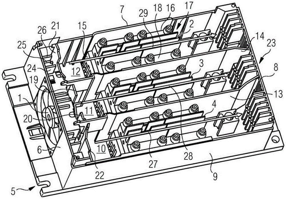
图1示出了低压开关设备的下部设备区域的透视图,该低压开关设备具有在此示例性地设计为风扇的冷却件和用于下游的功率电子构件的空气穿流通道的规定设计;FIG. 1 shows a perspective view of the lower installation region of a low-voltage switchgear with a cooling element, which is here by way of example designed as a fan, and a predetermined design of an air passage for downstream power electronics components;
图2示出了具有图1的风扇和规定的空气流通道的下部设备区域的局部透视图;Figure 2 shows a partial perspective view of the lower equipment area with the fan of Figure 1 and defined air flow channels;
图3示出了具有规定的空气流通道的中部壳体件的透视图,该空气流通道形成下部设备区域的气流通道的延续;Figure 3 shows a perspective view of a middle housing part with defined air flow channels forming a continuation of the air flow channels in the lower equipment area;
图4示出了根据图3的视图的不具有布线电路板的俯视图;FIG. 4 shows a top view of the circuit board without wiring according to the view of FIG. 3;
图5示出了具有规定的空气流通道的上部壳体件的透视图,该空气流通道形成中部壳体件的空气流通道的延续;Figure 5 shows a perspective view of the upper housing part with defined air flow channels forming a continuation of the air flow channels of the middle housing part;
图6示出了根据本发明的具有壳体的低压开关设备的透视图;Figure 6 shows a perspective view of a low voltage switchgear with a housing according to the present invention;
图7示出了根据图6的低压开关设备的透视图,其具有壳体中的用于向外排放空气流的格栅开口。Fig. 7 shows a perspective view of the low-voltage switchgear according to Fig. 6 with a grille opening in the housing for exhausting the air flow to the outside.
图1示出了根据本发明的低压开关设备的下部设备区域,该低压开关设备具有冷却件1和用于下游的功率电子构件2、3、4的空气穿流通道的规定设计,该冷却件1在此示例性地设计为单独的风扇。FIG. 1 shows the lower installation area of a low-voltage switchgear according to the invention, which has a cooling element 1 and a defined design of air passages for downstream power
根据本发明的低压开关设备优选具有直角六面体状的壳体下部件,该壳体下部件具有壳体底面,在该壳体底面上彼此以大约呈90°角布置有四个侧壁6、7、8、9并且通过壳体顶面封闭该侧壁。低压开关设备可以在壳体5之内被分成两个壳体区域,即下部和上部区域。上部壳体区域可以出于构造上的和功能上的原因被设计为一件式或者多件式,在此所示的解决方案中,上部壳体区域由中部壳体件和上部壳体件组成。The low-voltage switchgear according to the invention preferably has a hexahedron-shaped housing lower part with a housing base on which four
在下部的设备区域中优选布置有在此设计为风扇的冷却件1,该冷却件被定位于侧壁6之内。在内侧上,壳体下部件中风扇后的区域优选被划分成三个腔室10、11、12。所述划分是通过在壳体内部中置入的分隔壁13、14来实现的。由此形成的腔室10、11、12设计在壳体下部的彼此对置的侧壁7、9之间,使得在其中定位的功率电子构件2、3、4彼此平行地并且在空气通道的流动方向的纵向上定向,通过风扇向该空气通道供给冷空气。功率电子构件2、3、4优选以直角六面体状地设计,其具有四个侧壁15、16、17、18、一个顶面和一个底面。A cooling element 1 , here designed as a fan, is preferably arranged in the lower plant area, which cooling element is positioned within the
中部腔室11直接定位在风扇后,即沿气流方向居中地定位。其他两个腔室10、12分别布置在低压开关设备的壳体下部件的彼此对置的外侧壁7、9上。风扇后分别作为后置的腔室10、11、12的组成部分布置有用于空气穿流的导气壁19、20、21、22。为此,在中部腔室11中优选设计两个彼此对置的导气壁19、20。对于外侧的腔室10、12优选分别定位有从壳体的相应的侧壁7、9向内延伸的导气壁21、22。The central chamber 11 is positioned directly behind the fan, ie centrally in the direction of the airflow. The other two
中部腔室11的平行设计的分隔壁13、14在导气壁之后优选在气流方向上交错设计,使得它们尽管依旧平行于壳体下部的侧壁7、9延伸,然而在保持彼此距离的情况下相对于两个侧壁7、9中的一个更近地定向。中部腔室11的这些分隔壁13、14在与导气壁对置的侧边上面向彼此定向地设计,优选具有大约10至20°的角度,从而形成狭窄部23。The parallel-designed
外侧腔室10、12的子壁件、也即导气壁21、22分别在居中定位的风扇的侧旁定义腔室,该腔室优选通过彼此平行定向地指向内的导气壁24、25、26在侧壁6上进一步地被分隔并且构成规定的空气通道。The sub-wall elements of the
另外的流动障碍在此空气通道的空气进入区域中被放置在功率电子构件2、3、4的底部、侧部和上方。这些流动通道调整实现了中部通道11的较小的穿流,该中部通道11在流体技术上是最为有利的。Further flow obstacles are placed at the bottom, sides and above the power
不同大小的开口确保对于两个外侧的功率部件2、4大致相同的穿流或者冷却作用。因此,在中部区域的空气通路小于在外侧边界区域中的空气通路。The differently sized openings ensure approximately the same flow or cooling effect for the two
沿箭头方向所示的分支空气流27、28、29在三个腔室10、11、12中在其强度方面设计为不同的。The branch air flows 27 , 28 , 29 shown in the direction of the arrows are designed to be different in their intensity in the three
在图2中示出了具有风扇和规定的空气流通道的下部设备区域的局部图。风扇布置在侧壁6中。在风扇侧旁,通过导气壁21、22和侧壁6或者7、9设计有较小的腔室或者通风井,其通过风扇被空气穿流。通过导气壁24、25、26将空气输送入规定的气流通道31、32中。此外,通过风扇吸入的空气的一部分被导引到风扇上方的区域30中。A partial view of the lower plant area with a fan and defined air flow channels is shown in FIG. 2 . The fan is arranged in the
图3示出了中部壳体件,其具有从下部设备区域中延续的规定的空气流通道31、32以及具有从下部设备区域的区域30中延续的空气流通道33。中部壳体件具有基本上封闭的具有凹部34a的隔板34,在隔板34上布置有电路板35,尤其RC-布线电路板。FIG. 3 shows the middle housing part with the defined
图4示出了不具有电路板35的中部设备区域。FIG. 4 shows the middle device area without the
在图5中示出了具有规定气流通路36的上部壳体件,该空气流通道36构成从中部壳体件中的空气流通路31、32、33的延续。上部壳体件具有凹部37、38,在该凹部37、38中能够定位有控制部件和通信模块。FIG. 5 shows the upper housing part with a defined
图6示出了根据本发明的具有壳体的低压开关设备,其中在侧壁6中在下部的设备区域中布置有风扇。在正面39安置有控制部件40。另外,在此图示中能够看到三个壳体件41、42、44的布置方式。在下部壳体件41中布置有风扇和接口43。在中部壳体件42中布置有RC-布线电路板。在上部壳体件44中安装有控制部件40。FIG. 6 shows a low-voltage switchgear according to the invention with a housing, wherein a fan is arranged in the
在图7中示出了根据图6的低压开关设备,其具有壳体的侧壁8中的用于向外输送空气流的格栅开口45。FIG. 7 shows the low-voltage switchgear according to FIG. 6 , which has
根据本发明的低压开关设备的特征部分的特征是,即使在不高于650A的区域中的设备额定电流的情况下,也能实现对功率电子构件的可靠的调温。A characteristic feature of the low-voltage switchgear according to the invention is that a reliable temperature control of the power electronic components is achieved even with a nominal current of the device in the region of up to 650A.
附图标记清单List of reference numbers
1 冷却件1 cooling element
2 功率电子构件2 Power electronics components
3 功率电子构件3 Power electronics components
4 功率电子构件4 Power electronics components
5 壳体5 shell
6 侧壁6 side walls
7 侧壁7 side walls
8 侧壁8 side walls
9 侧壁9 side walls
10 腔室10 chambers
11 腔室11 chambers
12 腔室12 chambers
13 分隔壁13 dividing wall
14 分隔壁14 dividing wall
15 侧壁15 side walls
16 侧壁16 side walls
17 侧壁17 Side walls
18 侧壁18 side walls
19 导气壁19 Air guide wall
20 导气壁20 Air guide wall
21 导气壁21 Air guide wall
22 导气壁22 Air guide wall
23 狭窄部23 Stenosis
24 导气壁24 Air guide wall
25 导气壁25 Air guide wall
26 导气壁26 Air guide wall
27 分支空气流27 branch air flow
28 分支空气流28 branch air flow
29 分支空气流29 branch air flow
30 区域30 areas
31 空气流通道31 Air flow channel
32 空气流通道32 Air flow channels
33 空气流通道33 Air flow channel
34 隔板34 Separator
34a 凹部34a Recess
35 电路板35 circuit boards
36 空气流通道36 Air flow channels
37 凹部37 Recess
38 凹部38 recess
39 前侧39 Front
40 控制部件40 Control parts
41 下部壳体件41 Lower housing part
42 中部壳体件42 Middle housing part
43 接口43 ports
44 上部壳体件44 Upper housing part
45 格栅开口45 Grille opening
Claims (8)
Applications Claiming Priority (3)
| Application Number | Priority Date | Filing Date | Title |
|---|---|---|---|
| EP17203565.1 | 2017-11-24 | ||
| EP17203565.1A EP3490351B1 (en) | 2017-11-24 | 2017-11-24 | Low voltage switching device with a defined cooling arrangement |
| PCT/EP2018/081160 WO2019101589A1 (en) | 2017-11-24 | 2018-11-14 | Low-voltage switching device having a defined cooling arrangement |
Publications (2)
| Publication Number | Publication Date |
|---|---|
| CN111386754A true CN111386754A (en) | 2020-07-07 |
| CN111386754B CN111386754B (en) | 2022-04-15 |
Family
ID=60473346
Family Applications (1)
| Application Number | Title | Priority Date | Filing Date |
|---|---|---|---|
| CN201880075705.6A Active CN111386754B (en) | 2017-11-24 | 2018-11-14 | Low-voltage switchgear with prescribed cooling arrangements |
Country Status (4)
| Country | Link |
|---|---|
| US (1) | US11304330B2 (en) |
| EP (1) | EP3490351B1 (en) |
| CN (1) | CN111386754B (en) |
| WO (1) | WO2019101589A1 (en) |
Families Citing this family (3)
| Publication number | Priority date | Publication date | Assignee | Title |
|---|---|---|---|---|
| FR3091461B1 (en) * | 2019-01-02 | 2020-12-04 | Safran Electrical & Power | Electrical distribution module compartmentalized by partitions comprising ventilation channels and / or passage of control cables |
| CN112996327B (en) | 2021-02-19 | 2023-08-15 | 阳光电源股份有限公司 | a power cabinet |
| US11958403B2 (en) * | 2022-05-23 | 2024-04-16 | Caterpillar Inc. | Rooftop structure for semi-autonomous CTL |
Citations (7)
| Publication number | Priority date | Publication date | Assignee | Title |
|---|---|---|---|---|
| CN1040726A (en) * | 1988-08-31 | 1990-03-21 | 株式会社日立制作所 | Conversion equipment |
| CN1939107A (en) * | 2004-04-05 | 2007-03-28 | 西门子公司 | Engine control device |
| CN101466250A (en) * | 2007-12-21 | 2009-06-24 | 罗伯特.博世有限公司 | Device unit with cooling air channels |
| CN204792426U (en) * | 2014-03-07 | 2015-11-18 | Abb技术有限公司 | A cooling device for power electronic equipment |
| CN205142750U (en) * | 2013-01-22 | 2016-04-06 | 艾思玛太阳能技术股份公司 | Inverter with two-piece housing |
| CN105939095A (en) * | 2016-06-27 | 2016-09-14 | 武汉中直电气股份有限公司 | Charging device power module |
| CN206533653U (en) * | 2017-03-17 | 2017-09-29 | 厦门科华恒盛股份有限公司 | A kind of power cell |
Family Cites Families (6)
| Publication number | Priority date | Publication date | Assignee | Title |
|---|---|---|---|---|
| US5831847A (en) * | 1997-02-05 | 1998-11-03 | Jerome Industries Corp. | Power supply with separated airflows |
| US6359779B1 (en) * | 1999-04-05 | 2002-03-19 | Western Digital Ventures, Inc. | Integrated computer module with airflow accelerator |
| CN101202529A (en) * | 2006-12-11 | 2008-06-18 | 丹佛斯传动有限公司 | Electronic device and motor frequency converter |
| DE102007003329B3 (en) * | 2007-01-17 | 2008-04-10 | Siemens Ag | Cooling arrangement for arranged in a housing electrical components of a soft starter, and soft starter |
| US9007746B2 (en) * | 2012-12-12 | 2015-04-14 | Siemens Industry, Inc. | Modular draw out fan module with chimney design for cooling components in low voltage switchgear |
| DE102014116084A1 (en) * | 2014-11-04 | 2016-05-04 | Sma Solar Technology Ag | Inverter and method for cooling an inverter |
-
2017
- 2017-11-24 EP EP17203565.1A patent/EP3490351B1/en active Active
-
2018
- 2018-11-14 US US16/764,062 patent/US11304330B2/en active Active
- 2018-11-14 WO PCT/EP2018/081160 patent/WO2019101589A1/en not_active Ceased
- 2018-11-14 CN CN201880075705.6A patent/CN111386754B/en active Active
Patent Citations (7)
| Publication number | Priority date | Publication date | Assignee | Title |
|---|---|---|---|---|
| CN1040726A (en) * | 1988-08-31 | 1990-03-21 | 株式会社日立制作所 | Conversion equipment |
| CN1939107A (en) * | 2004-04-05 | 2007-03-28 | 西门子公司 | Engine control device |
| CN101466250A (en) * | 2007-12-21 | 2009-06-24 | 罗伯特.博世有限公司 | Device unit with cooling air channels |
| CN205142750U (en) * | 2013-01-22 | 2016-04-06 | 艾思玛太阳能技术股份公司 | Inverter with two-piece housing |
| CN204792426U (en) * | 2014-03-07 | 2015-11-18 | Abb技术有限公司 | A cooling device for power electronic equipment |
| CN105939095A (en) * | 2016-06-27 | 2016-09-14 | 武汉中直电气股份有限公司 | Charging device power module |
| CN206533653U (en) * | 2017-03-17 | 2017-09-29 | 厦门科华恒盛股份有限公司 | A kind of power cell |
Also Published As
| Publication number | Publication date |
|---|---|
| US11304330B2 (en) | 2022-04-12 |
| EP3490351B1 (en) | 2020-11-11 |
| CN111386754B (en) | 2022-04-15 |
| WO2019101589A1 (en) | 2019-05-31 |
| EP3490351A1 (en) | 2019-05-29 |
| US20200375063A1 (en) | 2020-11-26 |
Similar Documents
| Publication | Publication Date | Title |
|---|---|---|
| US10375851B2 (en) | Electrical cabinet with improved heat dissipation | |
| US8634193B2 (en) | Device and method using induction to improve natural convection cooling | |
| JP4212625B2 (en) | Equipment and network cabinet cooling system, and equipment and network cabinet cooling method | |
| CN111386754B (en) | Low-voltage switchgear with prescribed cooling arrangements | |
| US8810087B2 (en) | Motor unit | |
| EP3001786B1 (en) | Inverter heat-dissipation device and inverter | |
| US20120261100A1 (en) | Power converter | |
| JP6589295B2 (en) | Power converter | |
| JP5554651B2 (en) | Power converter | |
| CN106059257A (en) | Cooled power conversion assembly | |
| CN110235536A (en) | Cooling device and robot controller with this cooling device | |
| EP3493388B1 (en) | Power conversion device | |
| EP3900500B1 (en) | An arrangement for cooling power semiconductor devices of a converter | |
| CN112956092A (en) | Gas Insulated Switchgear | |
| JP4498367B2 (en) | Power panel | |
| CN103887720A (en) | Electronic Control Cabinet With Cooling | |
| JP6219174B2 (en) | Electrical equipment | |
| CN111684870A (en) | Multi-compartment electrical installations with shared cooling components | |
| JP2015065747A (en) | Power switchboard device | |
| US9596784B2 (en) | Multi-chamber cooling system | |
| US11259439B2 (en) | Low-voltage switching device having an asymmetrically guided air flow-based cooling system | |
| US20240414874A1 (en) | Robot controller cabinet and robot comprising such a cabinet | |
| JP2013157466A (en) | Electric power conversion apparatus | |
| JP7535983B2 (en) | Electrical Equipment Unit | |
| GB2351344A (en) | An enclosure for electrical equipment |
Legal Events
| Date | Code | Title | Description |
|---|---|---|---|
| PB01 | Publication | ||
| PB01 | Publication | ||
| SE01 | Entry into force of request for substantive examination | ||
| SE01 | Entry into force of request for substantive examination | ||
| GR01 | Patent grant | ||
| GR01 | Patent grant |