CN111376051A - Intelligent automatic fan shell production equipment - Google Patents
Intelligent automatic fan shell production equipment Download PDFInfo
- Publication number
- CN111376051A CN111376051A CN202010294712.4A CN202010294712A CN111376051A CN 111376051 A CN111376051 A CN 111376051A CN 202010294712 A CN202010294712 A CN 202010294712A CN 111376051 A CN111376051 A CN 111376051A
- Authority
- CN
- China
- Prior art keywords
- locate
- support
- cavity
- welding
- motor
- Prior art date
- Legal status (The legal status is an assumption and is not a legal conclusion. Google has not performed a legal analysis and makes no representation as to the accuracy of the status listed.)
- Granted
Links
- 238000004519 manufacturing process Methods 0.000 title claims abstract description 20
- 241000886569 Cyprogenia stegaria Species 0.000 title claims abstract description 14
- 239000000463 material Substances 0.000 claims abstract description 189
- 238000003466 welding Methods 0.000 claims abstract description 79
- 238000005452 bending Methods 0.000 claims abstract description 27
- 238000001125 extrusion Methods 0.000 claims description 35
- 230000005540 biological transmission Effects 0.000 claims description 27
- 230000000712 assembly Effects 0.000 claims description 10
- 238000000429 assembly Methods 0.000 claims description 10
- 238000010438 heat treatment Methods 0.000 claims description 10
- 238000000034 method Methods 0.000 claims description 10
- 230000008859 change Effects 0.000 claims description 4
- 239000002184 metal Substances 0.000 description 18
- 229910052751 metal Inorganic materials 0.000 description 18
- 230000009471 action Effects 0.000 description 9
- XEEYBQQBJWHFJM-UHFFFAOYSA-N Iron Chemical compound [Fe] XEEYBQQBJWHFJM-UHFFFAOYSA-N 0.000 description 8
- 230000008569 process Effects 0.000 description 8
- 230000000694 effects Effects 0.000 description 6
- 230000001965 increasing effect Effects 0.000 description 5
- 229910052742 iron Inorganic materials 0.000 description 4
- 230000000149 penetrating effect Effects 0.000 description 4
- 240000002836 Ipomoea tricolor Species 0.000 description 3
- 230000005484 gravity Effects 0.000 description 3
- 238000005096 rolling process Methods 0.000 description 3
- 238000012423 maintenance Methods 0.000 description 2
- 241000251468 Actinopterygii Species 0.000 description 1
- 238000005299 abrasion Methods 0.000 description 1
- 238000001816 cooling Methods 0.000 description 1
- 230000007423 decrease Effects 0.000 description 1
- 230000007547 defect Effects 0.000 description 1
- 238000010586 diagram Methods 0.000 description 1
- 238000006073 displacement reaction Methods 0.000 description 1
- 230000002708 enhancing effect Effects 0.000 description 1
- 239000002360 explosive Substances 0.000 description 1
- 210000001503 joint Anatomy 0.000 description 1
- 238000010030 laminating Methods 0.000 description 1
- 238000003825 pressing Methods 0.000 description 1
- 238000007665 sagging Methods 0.000 description 1
- 239000007921 spray Substances 0.000 description 1
- 230000032258 transport Effects 0.000 description 1
- 238000009423 ventilation Methods 0.000 description 1
Images




Classifications
-
- B—PERFORMING OPERATIONS; TRANSPORTING
- B23—MACHINE TOOLS; METAL-WORKING NOT OTHERWISE PROVIDED FOR
- B23P—METAL-WORKING NOT OTHERWISE PROVIDED FOR; COMBINED OPERATIONS; UNIVERSAL MACHINE TOOLS
- B23P23/00—Machines or arrangements of machines for performing specified combinations of different metal-working operations not covered by a single other subclass
-
- B—PERFORMING OPERATIONS; TRANSPORTING
- B23—MACHINE TOOLS; METAL-WORKING NOT OTHERWISE PROVIDED FOR
- B23Q—DETAILS, COMPONENTS, OR ACCESSORIES FOR MACHINE TOOLS, e.g. ARRANGEMENTS FOR COPYING OR CONTROLLING; MACHINE TOOLS IN GENERAL CHARACTERISED BY THE CONSTRUCTION OF PARTICULAR DETAILS OR COMPONENTS; COMBINATIONS OR ASSOCIATIONS OF METAL-WORKING MACHINES, NOT DIRECTED TO A PARTICULAR RESULT
- B23Q7/00—Arrangements for handling work specially combined with or arranged in, or specially adapted for use in connection with, machine tools, e.g. for conveying, loading, positioning, discharging, sorting
- B23Q7/003—Cyclically moving conveyors
Landscapes
- Engineering & Computer Science (AREA)
- Mechanical Engineering (AREA)
- Physics & Mathematics (AREA)
- Optics & Photonics (AREA)
- Bending Of Plates, Rods, And Pipes (AREA)
Abstract
The invention discloses intelligent automatic fan shell production equipment which comprises a blanking device, a bending device and a welding device, wherein the bending device is arranged on one side of the blanking device, and the welding device is arranged at the tail end of the bending device; welding set is including setting up subaerial first frame, locating material passageway in the first frame, locating the first support at material passageway both ends, locating first drive belt on the support, locating material passageway first half's multiunit leading wheel, locate lug on the first drive belt, locate be used for driving the first motor in first drive belt on the first support, locate wherein on a set of leading wheel location structure and locate material passageway second half's welded structure. According to the invention, through the arrangement of the positioning structure and the welding structure, the automatic welding of the fan shell is completed, the working efficiency is effectively improved, meanwhile, the welding seam is automatically positioned, and the cost for manually carrying and adjusting the fan shell is effectively reduced.
Description
Technical Field
The invention belongs to the technical field of fan processing, and particularly relates to intelligent automatic fan shell production equipment.
Background
The axial flow fan occupies a great field in daily life, can be used for ventilation of places such as general factories, warehouses, offices, houses and the like, can also be used for air coolers (air coolers), evaporators, condensers, spray coolers and the like, also has a mine axial flow fan, adopts anticorrosive materials and explosion-proof measures for anticorrosive and explosion-proof type axial flow fans, is matched with an explosion-proof motor, and can be used for conveying explosive, volatile and corrosive gas.
In axial fan's production process, fan shell's production has taken up extremely important partly, fan shell's production process is through having certain angle to extrude the messenger iron plate and carry out certain degree bending with a thinner iron plate between roller and the roller, when monoblock iron plate bending becomes a circular shape tubulose lamellar body, take off it from the machine, thereby adopt artificial mode to weld both sides and form a complete annular structure afterwards, but in daily production process, the iron plate after the bending is accomplished needs the manual work to take off it, carry out manual welding's mode afterwards, or move the welding seam to the fixed position and weld afterwards through carrying to the manual work on the automatic weld machine, this mode process time is long, the cost of labor is higher simultaneously.
Disclosure of Invention
In order to overcome the defects of the prior art, the invention provides the fan shell production equipment which is high in intelligent automatic processing efficiency and low in labor cost.
In order to achieve the purpose, the invention adopts the following technical scheme: an intelligent automatic fan shell production device comprises a blanking device, a bending device arranged on one side of the blanking device and a welding device arranged at the tail end of the bending device; the welding device comprises a first rack arranged on the ground, a material channel arranged in the first rack, first supports arranged at two ends of the material channel, a first transmission belt arranged on the supports, a plurality of groups of guide wheels arranged at the front half part of the material channel, a lug arranged on the first transmission belt, a first motor arranged on the first supports and used for driving the first transmission belt, a positioning structure arranged on one group of guide wheels and a welding structure arranged at the rear half part of the material channel; the guide wheels are arranged in a circle along the radial direction of the inner wall of the material channel to form a group, and a plurality of groups are arranged along the axial direction of the material channel; the motor on the first support rotates to drive the first driving belt in the first support to move, the moving driving belt drives the bent metal sheet to move in the material channel, the first driving belt is provided with a convex block, the surface of the first driving belt is made of smooth materials and is mainly abutted against the bottom of the bent metal sheet through the convex block to push the tubular metal sheet to move, the tubular metal sheet is abutted against the driving wheel to move, the smoothness of the movement of the metal sheet is ensured, the first driving belt drives the material to pass through the positioning structure to complete the positioning of a butt seam, the material is welded through the welding structure along with the continuous advance of the driving belt after the positioning is completed, and the automatic and efficient welding process is completed. Simultaneously, the working efficiency is effectively improved, automatic positioning is carried out on welding seams, the necessity that manual carrying is needed to adjust the fan shell and then manual welding or manual butt joint is effectively reduced, and the labor cost is effectively reduced.
The guide wheel comprises a hole groove formed in the inner wall of the material channel pipe, a rotating shaft with one end arranged in the hole groove, a second support arranged at the other end of the rotating shaft, and a friction wheel arranged on the second support; when the material gets into in the material passageway, because the material of just crooked completion has certain elastic stress, through the form that sets up the leading wheel, carry out certain degree parcel to it to evenly to its application of force, avoided it to open because elastic stress after the bending, thereby the welding seam is too big when making the welding, thereby has effectively guaranteed the welding quality in later stage.
The positioning structure comprises a first cavity arranged on the inner wall of the material channel, a first through groove arranged on the first cavity, a top block penetrating through the first through groove and moving back and forth, a first inclined plane arranged on the top block, a second inclined plane arranged on the second support, a second through groove arranged on the inner wall of the material channel, a clamping rod penetrating through the second through groove and moving back and forth, an extending block arranged at the top end of the clamping rod, a third inclined plane arranged on the extending block, a lever arranged in the first cavity, a first rotating piece arranged in the middle of the lever, a first elastic piece arranged in the first cavity and used for resetting the clamping rod, a rolling piece arranged on the extending block and a clamping piece arranged between two groups of guide wheels; the two ends of the lever are respectively rotatably connected to the clamping rod and the bottom of the ejector block, when materials enter the material channel, if a welding seam is not located at the uppermost position in the movement process of a metal sheet, the materials extrude the third inclined surface on the extension block to extrude the clamping rod to move upwards to extrude the first elastic piece, the lever is extruded to jack the ejector block, the first inclined surface on the ejector block and the second inclined surface on the second support are extruded mutually to finish the offset of the friction wheel, the offset friction wheel is attached to the surface of the tubular materials, so that the materials rotate under the action of the friction wheel, the rest guide rollers easily rotate around the rotating shaft and turn to the same direction as the guide wheel limited by the ejector block, and the resistance to the rotation of the materials is reduced; when the material rotates by a certain angle, when the welding seam is positioned right above, the clamping rod can be bounced under the action of the first elastic piece, the clamping is connected into the welding seam, at the moment, the lever rotates around the first rotating piece again, the ejector block is pulled back inwards, the second support loses the limit of the ejector block, the guide wheel recovers freedom, the clamping rod is limited to the clamping of the tubular material, the guide wheel recovers the direction parallel to the axis of the material pipeline, so that the tubular material is not deviated in any radial direction, only the guiding effect is achieved, the positioning of the welding seam of the material is completed, the subsequent welding process is facilitated, the time cost for manually carrying and butting the material is effectively reduced, the processing efficiency is effectively improved, meanwhile, the manual damage to hands of the material is avoided due to manual carrying, and the manual safety is improved.
The clamping piece comprises a groove arranged on the inner wall of the material channel, a second rotating piece arranged in the groove, a rotating rod with one end connected to the second rotating piece, a second elastic piece arranged in the groove and used for resetting the rotating rod, and a round angle arranged on the top end of the rotating rod; before the joint piece does not advance in the joint advances the welding seam, the extrusion of material will be received to the swing arm, thereby make the swing arm round the second rotating member at the recess internal rotation, extrude the second elastic component, make the fillet laminating of ejector pin in the surface removal of material, and when the welding seam of material is located the material directly over, when the welding seam is gone into to the joint piece card, the swing arm will rotate under the effect of second elastic component, thereby the joint goes into in the welding seam, it is spacing to the material, thereby prevent that the material from leading to the skew of tubulose material owing to the conveying in the distance before moving the welding point, thereby lead to follow-up welding seam skew, welder can't correctly weld, even welder touches the condition that leads to welder to damage with the material and takes place, the damage of apparatus has effectively been avoided, thereby the maintenance cost of apparatus has been.
The welding structure comprises a plurality of groups of extrusion assemblies arranged at the rear half section of the material channel, a second motor arranged between the extrusion assemblies, a slotting cutter connected to the second motor, a third motor arranged between the extrusion assemblies, a rotary table arranged on the third motor, a welding gun arranged on the rotary table, and a positioning wheel arranged between the extrusion assemblies; the extrusion wheels are arranged into one group along the radial direction of the material channel, and a plurality of groups are arranged along the axial direction; the extrusion wheel comprises a second cavity arranged on the inner wall of the material channel, a first sliding block arranged in the second cavity and capable of moving back and forth, a third support arranged on the first sliding block, an extrusion wheel arranged on the third support, and a third elastic piece arranged in the second cavity and used for resetting the first sliding block; the tubular material enters a subsequent welding area under the driving of the driving belt, at the moment, the extrusion wheel is attached to the surface of the material, a certain pressure is applied to the surface of the material under the action of the third elastic piece to clamp the tubular material to a certain degree, so that the width of a welding seam above the material is limited, the condition that the welding is not firm due to overlarge width of the welding seam is avoided, meanwhile, the extrusion wheel is used for limiting the rotation of the material to enable the welding seam to be always in the uppermost position, the grooving cutter is used for processing the welding seam under the driving of the second motor to enable the material to generate a V-shaped groove so as to improve the welding quality, the material after being cut into the groove opening is enabled to be prevented from deviating by the positioning wheel during continuous operation and then enters the lower part of a rear welding gun, and the rotation of the rotary table is used for driving the welding gun to weld round the circle under the driving of the second motor, by means of circular welding, the existing time of a molten pool is longer, and the welding strength is increased.
The blanking device comprises a second frame arranged on the ground, a material cavity arranged on the second frame, a discharge port arranged at the bottom of the material cavity, an air cylinder arranged at one side of the material cavity, a push block arranged on the air cylinder, a third cavity arranged below the material cavity, and a heating pipe arranged in the third cavity, wherein the material is arranged in the material cavity, the push block pushes the material out of the discharge port under the action of the air cylinder, so that the material enters the bending device, the material at the bottommost lower layer is heated continuously under the heating of the heating pipe in the third cavity before being pushed out by the push block, so that the metal sheet is easier to bend, the subsequent bending is facilitated, meanwhile, a certain temperature still exists in the metal sheet after the bending is completed, the preheated metal sheet can effectively prevent cold cracks, hot cracks and a heat affected zone from generating hardened tissues, the cooling speed can be slowed down, and cracks are prevented from being generated in a welding seam, thereby enhancing the welding effect and effectively increasing the welding quality.
The bending device comprises a third rack, a fourth cavity arranged on the third rack, a fourth motor arranged on the wall of the fourth cavity, a threaded rod arranged on the fourth motor, a force arm sleeved on the threaded rod, a squeezing roller arranged on the force arm, a fourth support arranged below the squeezing roller, a rotating roller arranged on the fourth support, a fifth motor arranged on one side of the fourth support and used for driving the rotating roller, a conveying structure arranged below the force arm and sliding tracks arranged on two sides of the squeezing roller; the force arm is sleeved on the threaded rod and is connected with the threaded rod through threads, so that the force arm can move up and down on the threaded rod when the threaded rod rotates, when a metal sheet enters the bending device, the rotary roller takes out a material from the blanking device under the drive of the fifth motor, then the fourth motor rotates to drive the threaded rod to rotate, the force arm is controlled to move downwards, the extrusion roller extrudes the material, the material is continuously extruded and bent in the continuous rotation process of the rotary roller, the fifth motor rotates reversely when the material is about to separate from the rotary roller, the fourth motor drives the power arm to continuously descend until the bending of the material reaches a certain angle to form an annular shape, the possibility of material fracture and damage caused by overlarge bending curvature of the material at one time is effectively reduced in a mode of repeatedly and gradually extruding the material, and the stress generated after the material is bent is reduced at the same time, the deformation caused by material resilience due to stress is reduced, the yield of bending of the material is increased, and subsequent welding is facilitated.
The conveying structure comprises a connecting block arranged below the force arm, a fifth support arranged on the connecting block, a transmission roller arranged on the fifth support, a transmission belt sleeved on the transmission roller, a first gear arranged on the fifth support and connected with the transmission roller, a sixth support arranged on the fifth support, a second gear arranged on the sixth support and a third gear arranged on the rotating roller; the first gear and the second gear are kept in a meshed state; after the material is bent, the force arm moves upwards under the rotation of the fourth motor, so as to drive the fifth bracket to move upwards, thereby engaging the third gear and the second gear, the third gear rotating along with the fifth motor drives the second gear to rotate, the first gear engaged with the second gear drives the transmission roller to drive the transmission belt sleeved on the transmission roller to rotate, so that the transmission belt drives the material to be transmitted to the backward material channel, the rotating roller drives the material to rotate continuously above the material while the transmission belt drives the material, so that the material enters the material channel in a rotating manner, the process that the material enters the material channel is facilitated, the possibility that the material is flattened under the action of gravity, the side length of the material in the transverse direction cannot enter the material channel is avoided, the side length of the material cannot enter the material channel due to the fact that the material is touched with the outer wall of the material channel, the appearance of an instrument is abraded, and the abrasion of the instrument is, the maintenance cost is reduced.
The sliding track comprises an auxiliary platform which is arranged opposite to the second rack by taking the squeezing roller as a symmetrical center, a first ramp arranged on the auxiliary platform, a second ramp arranged on the second rack, supporting bars arranged on the first ramp and the second ramp, a third rotating piece arranged below the supporting bars, a fourth elastic piece arranged on one side of the supporting bars, a fourth rotating piece arranged at the bottom of the second ramp, and a connecting block with one end connected with the third rotating piece; when tubular material has not formed the circular shape structure completely yet, because the removal of changeing the roller, the material exists because the flagging problem of gravity, through the setting of the first ramp on the auxiliary table and the second ramp in the second frame, at this stage, the support bar will provide a support for the sheetmetal under the effect of fourth elastic component, the reverse deformation of material and the material of having avoided because material gravity leads to because the distal end is heavier thereby the material from the condition emergence of slippage between the roller, the support bar will play the effect of gathering together the material inwards, it is too big to avoid buckling department's atress, after the material is rolled up into the ring shape, two support bars will form a form similar to the ring, play fixed effect. The stability of the instrument is increased.
According to the invention, through the arrangement of the positioning structure and the welding structure, the automatic welding of the fan shell is completed, the working efficiency is effectively improved, meanwhile, the welding seam is automatically positioned, and the cost for manually carrying and adjusting the fan shell is effectively reduced.
Drawings
FIG. 1 is a schematic structural diagram of the present invention.
Fig. 2 is an enlarged schematic view of the welding apparatus.
Fig. 3 is a left side view of the welding device.
Fig. 4 is a schematic perspective cross-sectional view taken along line a-a of fig. 3.
Fig. 5 is an enlarged schematic view of a portion a of fig. 4.
Fig. 6 is a partially enlarged schematic view of fig. 5.
Fig. 7 is an enlarged schematic view of B in fig. 4.
Fig. 8 is an enlarged schematic view at C in fig. 4.
Fig. 9 is an enlarged schematic view of the blanking device.
Fig. 10 is a partially enlarged schematic view of fig. 9.
Fig. 11 is a front view of the blanking device.
Fig. 12 is a perspective cross-sectional view of fig. 11 taken along line B-B.
Fig. 13 is an enlarged schematic view at D in fig. 12.
Fig. 14 is an enlarged schematic view at E in fig. 12.
Fig. 15 is an enlarged schematic view of the bending apparatus.
Fig. 16 is a right side view of the bending apparatus.
Fig. 17 is a perspective cross-sectional view of fig. 16 taken along line C-C.
Fig. 18 is a partially enlarged view of fig. 15.
Detailed Description
As shown in fig. 1-18, an intelligent automatic blower casing production device comprises a blanking device 1, a bending device 2, and a welding device 3; the bending device 2 is arranged on one side of the blanking device, and the welding device 3 is arranged at the tail end of the bending device; the welding device 3 comprises a first frame 31, a material channel 32, a first bracket 33, a first transmission belt 34, a guide wheel 35, a bump 36, a first motor 37, a positioning structure 4 and a welding structure 5; the first frame 31 is arranged on the ground, the material channel 32 is arranged in the first frame, the first supports 33 are arranged at two ends of the material channel, the first transmission belts 34 are arranged on the supports, the guide wheels 35 are provided with a plurality of groups, 6 are arranged in the radial direction of the material pipeline, the 6 groups are 1 group, 8 groups are arranged in the axial direction of the material pipeline and are arranged on the front half part of the material channel, the convex block 36 is arranged on the first transmission belt, the first motor 37 is arranged on the first support and is used for driving the first transmission belts, the positioning structure 4 is arranged on one group of guide wheels, and the welding structure 5 is arranged on the rear half part of the material channel; . First frame is the block of a cuboid, and one through-hole that runs through in whole frame is offered to its middle section is material passageway, and the first conveyer belt is last to be provided with a lug at every interval distance, and the conveyer belt surface is smooth structure, plays the supporting role, and main conveying material supports through the lug and transports in the bottom of material, and prior art here no longer has been repeated for the market purchase is first motor.
As shown in fig. 5, the guide wheel 35 includes a hole groove 351, a rotation shaft 352, a second bracket 353, and a friction wheel 354; a hole groove 351 is formed in the inner wall of the material channel pipe, one end of a rotating shaft 352 is arranged in the hole groove, a second support 353 is arranged at the other end of the rotating shaft, and a friction wheel 354 is arranged on the second support; the empty groove is a hole formed in the inner wall of the material pipeline, the second support is inserted into the hole groove through a rotating shaft and can be rotatably arranged, and the friction wheel is arranged on the second support and can be rotatably connected to the wall relative to the material channel.
As shown in fig. 6, the positioning structure 4 includes a first cavity 41, a first through slot 42, a top block 43, a first inclined surface 44, a second inclined surface 45, a second through slot 46, a clamping rod 47, an extending block 48, a third inclined surface 49, a lever 410, a first rotating member 411, a first elastic member 412, a rolling member 413, and a clamping member 6; a first cavity 41 is arranged on the inner wall of the material channel, a first through groove 42 is arranged on the first cavity, a top block 43 is arranged in the first through groove in a penetrating manner and moves back and forth, a first inclined plane 44 is arranged on the top block, a second inclined plane 45 is arranged on the second support, a second through groove 46 is arranged on the inner wall of the material pipeline, a clamping rod 47 is arranged in the second through groove in a penetrating manner and moves back and forth, an extending block 48 is arranged at the top end of the clamping rod, a third inclined plane 49 is arranged on the extending block, a lever 410 is arranged in the first cavity, a first rotating piece 411 is arranged in the middle of the lever, a first elastic piece 412 is arranged in the first cavity and used for resetting the clamping rod, a rolling piece 413 is arranged on the extending block, and a clamping piece 6 is arranged between two groups of guide wheels; the positioning structure is arranged on a group of driving wheels which are close to the position of the material inlet, the positioning structure is arranged on the 4 th group, when the materials contact the fourth group, the materials just completely enter the material channel, and two ends of the lever are respectively and rotatably connected to the clamping rod and the bottom of the top block. The first cavity is a rectangular cavity structure, the first through groove and the second through groove are respectively arranged at two ends of the first cavity close to the side wall of the material channel, a lever structure is arranged in the first cavity, one end of the lever is connected with the top block, an inclined surface is arranged on the top block and corresponds to a third inclined surface on the second support, when the top block is ejected outwards, the second support rotates around a rotating shaft for a certain angle so as to control the deviation of the guide wheel, the friction wheel on the guide wheel is a wheel body with larger friction force, the friction force is larger and is attached to the surface of the material, when the material is transported through a first transmission belt, the whole material is rotated under the influence of the friction wheel, the other end of the lever is a clamping rod which is ejected outwards through a first elastic part, the other end of the clamping block is an extending block provided with an inclined surface, the extending block is provided with an inclined surface, the extension block can be extruded inwards through the movement of the material, so that the ejection of the ejection block is controlled, the guide wheel is deflected, and the structure is stable.
As shown in fig. 7, the clamping member 6 includes a groove 61, a second rotating member 62, a rotating rod 63, a second elastic member 64, and a round corner 65; the groove 61 is formed in the inner wall of the material channel, the second rotating piece 62 is arranged in the groove, one end of the rotating rod 63 is connected to the second rotating piece, the second elastic piece 64 is arranged in the groove and used for resetting the rotating rod, and the round angle 65 is arranged at the top end of the rotating rod; the joint spare sets up the position directly over, the recess is a convex inside sunken structure, the inside sets up there is the second rotating member, the swing arm is being connected on the second rotating member, the top of swing arm is provided with the fillet, be used for reducing the friction with the material surface, thereby reduce the possibility of swing arm to material surface fish tail, the swing arm passes through the second elastic component and supports, here second elastic component sets up to the flexure strip, make the swing arm be in the state of perpendicular to material passageway inner wall, but when the welding seam of material is directly over for reaching the material, will be compressed, when the joint advances in the welding seam, will play radial limiting displacement to the material, it can not rotate to have guaranteed that the material.
As shown in fig. 7-8, the welding structure 5 includes a pressing wheel 51, a second motor 52, a slotting cutter 53, a third motor 54, a turntable 55, a welding gun 56, and a positioning wheel 57; a plurality of groups of extrusion wheels 51 are arranged at the rear half section of the material channel, a second motor 52 is arranged between the extrusion components, a slotting cutter 53 is connected onto the second motor, a third motor 54 is arranged between the extrusion components, a rotary table 55 is arranged on the third motor, a welding gun 56 is arranged on the rotary table, and a positioning wheel 57 is arranged between the extrusion components; the extrusion assemblies are arranged into one group along the radial direction of the material channel, and are axially provided with a plurality of groups, the form of the extrusion wheels is basically the same as that of the guide wheels, the extrusion wheels are also 6 groups, and the extrusion wheels are provided with a plurality of groups, wherein the extrusion wheels are arranged into 6 groups; the extrusion assembly 51 comprises a second cavity 511, a first sliding block 512, a third bracket 513, an extrusion wheel 514 and a third elastic element 515; the second cavity 511 is arranged on the inner wall of the material channel, the first sliding block 512 is arranged in the second cavity and can move back and forth, the third support 513 is arranged on the first sliding block, the extrusion wheel 514 is arranged on the third support, and the third elastic element 515 is arranged in the second cavity and is used for resetting the first sliding block; the second motor, the third motor, the slotting cutter and the welding gun are all the prior art which is directly bought in the market and are not repeated, the slotting cutter is arranged at the position of the second group of the extrusion wheel, the welding gun is arranged behind the slotting cutter, the positioning wheel is a wheel body which is clamped in a V-shaped groove formed by the slotting cutter, the wheel body is in a flying saucer shape with clear edges and corners in the vertical direction, the upper end and the lower end of the flying saucer are attached to the V-shaped groove, the skirt edge of the flying saucer is embedded in the welding line to play a role in guiding and supporting, the size of the welding line is ensured, and the positions can be changed according to requirements under the condition of ensuring the sequence; the second cavity is a rectangle cavity and corresponds with the quantity and the position of extrusion wheel, and the extrusion wheel is an outside convex wheel body, thereby will extrude the material surface and consolidate when the material passes through, supports the form of extrusion wheel through the third elastic component and evenly applies force to the surface.
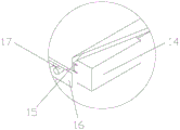
As shown in fig. 9-14, the blanking device 1 includes a second frame 11, a material cavity 12, a material outlet 13, an air cylinder 14, a pushing block 15, a third cavity 16, and a heating pipe 17; the second rack 11 is arranged on the ground, the material cavity 12 is arranged on the second rack, the discharge hole 13 is arranged at the bottom of the material cavity, the air cylinder 14 is arranged on one side of the material cavity, the push block 15 is arranged on the air cylinder, the third cavity 16 is arranged below the material cavity, and the heating pipe 17 is arranged in the third cavity; the material chamber here is the material chamber of a chute, and the discharge gate setting is in the bottom in material chamber, and the form that promotes the ejector pad through the cylinder pushes away the material from the bottom in material chamber with the material, and the cylinder is prior art here, and the third cavity is no longer being repeated herein for setting up a cavity structures in material chamber bottom, and inside is provided with the heating pipe, and the heating pipe is arranged according to continuous s type, makes the heating more even rapidly.
As shown in fig. 15-18, the bending apparatus 2 includes a third frame 21, a fourth cavity 22, a fourth motor 23, a threaded rod 24, a force arm 25, a squeeze roller 26, a fourth bracket 27, a rotating roller 28, a fifth motor 29, a conveying structure 7, and a sliding rail 8; a fourth cavity 22 is arranged on the third rack, a fourth motor 23 is arranged on the wall of the fourth cavity, a threaded rod 24 is arranged on the fourth motor, a force arm 25 is sleeved on the threaded rod, a squeezing roller 26 is arranged on the force arm, a fourth support 27 is arranged below the squeezing roller, a rotating roller 28 is arranged on the fourth support, a fifth motor 29 is arranged on one side of the fourth support and used for driving the rotating roller, a transmission structure 7 is arranged below the force arm, and sliding tracks 8 are arranged on two sides of the squeezing roller; the fourth cavity is the rectangle opening of setting in the third frame, the fourth motor sets up the top at the fourth cavity, a threaded rod is being connected, the arm of force is the block of a rectangular shape, the below is provided with the squeeze roll, it is provided with two to change the roller, and appear a closed angle triangle-shaped form upwards between the squeeze roll, the fifth motor sets up in the fourth support, the fourth support is the shape fifth motor setting of a side of connecting in the third frame and regarding as U type structure is connected with changeing the roller on the fourth support, the squeeze roll with change the roller and respectively take its part in other roles, the action of single part has been reduced, thereby stability between the part has been improved.
As shown in fig. 15-18, the conveying structure 7 includes a connecting block 71, a fifth bracket 72, a driving roller 73, a driving belt 74, a first gear 75, a sixth bracket 76, a second gear 77, and a third gear 78; the connecting block 71 is arranged below the force arm, the fifth support 72 is arranged on the connecting block, the driving roller 73 is arranged on the fifth support, the driving belt 74 is sleeved on the driving roller, the first gear 75 is arranged on the fifth support and connected with the driving roller, the sixth support 76 is arranged on the fifth support, the second gear 77 is arranged on the sixth support, and the third gear 78 is arranged on the rotating roller; the first gear and the second gear are kept in a meshed state; the connecting block is an I type block structure of connection below the arm of force, and the fifth support is two connection and is presented the lamellar bodies of L type on the connecting block between the connecting block, supports driving roller and drive belt clamp in the centre, and first gear is separated from the driving roller and is connected with the fifth support. The sixth support is two blocks for fixing the second gear and the first gear, the third gear is arranged above the second gear, and the second gear is meshed with the third gear when the force arm moves upwards after being sleeved on the rotating roller.
As shown in fig. 9-12 and 14, the sliding rail 8 includes an auxiliary platform 81, a first ramp 82, a second ramp 83, a supporting bar 84, a third rotating member 85, a fourth elastic member 86, a fourth rotating member 87, and a connecting block 88; the auxiliary table 81 is arranged opposite to the second rack by taking the squeezing roller as a symmetric center, the first ramp 82 is arranged on the auxiliary table, the second ramp 83 is arranged on the second rack, the supporting bar 84 is arranged on the first ramp and the second ramp, the third rotating piece 85 is arranged below the supporting bar, the fourth elastic piece 86 is arranged on one side of the supporting bar, the fourth rotating piece 87 is arranged at the bottom of the second ramp, and one end of the connecting block 88 is connected with the third rotating piece; the auxiliary table is a block corresponding to the second frame, the first ramp and the second ramp are two inclined arc surfaces which are respectively arranged on the auxiliary table and the second frame, the supporting bars are two strip-shaped blocks which are arc-shaped, the top end is a reverse small arc, is connected with the machine through a third rotating piece and is supported by an elastic piece through a fourth elastic piece at the position and tilts upwards, when the material moves to one side, the supporting strip plays a role of gathering the material inwards, so that the excessive stress at the bending part is avoided, when the material is coiled into a circular ring shape, the two supporting strips form a form similar to a circular ring to play a role in fixing, the connecting block is a triangular block body and forms a complete ramp with the second ramp, the triangular block body and the second ramp are connected through the fourth rotating piece, when the materials move outwards, the connecting block is jacked up, and when the materials are completely sent out, the discharge hole is sealed.
The specific working process is as follows:
the materials are accumulated in the material cavity 12, the bottommost material is heated by the heating pipe 17, so that the deformation capacity of the metal sheet is increased, then the pushing block 15 is pushed by the air cylinder 14, the pushing block moves outwards to push the materials outwards, when the head end of the material is contacted with the upper part of the rotating roller 28 which is farthest away, the control force arm 25 moves downwards, the rotating roller pulls the materials outwards, the extruding roller 26 presses the metal sheet downwards, so that the metal sheet is deformed, when the materials continuously move outwards, the materials are propped against the supporting strip 84 due to small variable quantity of the metal sheet, the supporting strip rotates under the pressure of the materials, so that the materials are supported, one end of the materials is prevented from excessively sagging, when the tail end of the materials is about to be separated from the rotating roller, the rotating roller rotates reversely, data can be obtained through calculation, so that the rotation of the rotating roller is controlled, the roller will drive the metal sheet to move back, and the discharge gate is sealed by connecting block 88 this moment, form a complete slope, thereby accomplish the same action with between the above-mentioned support bar, along with the continuous decline of squeeze roll, when reaching the specified degree, the material will be bent into an annular, and two support bar tops contact each other, form an annular and play certain supporting role, when the material becomes the tubulose that meets the requirements completely, the squeeze roll will continue to extrude for a certain time, reduce the influence of stress, the squeeze roll will move up under the arm of force drive afterwards, driving roller 73 and conveyer belt 74 below will drive whole tubulose metal sheet and remove, get into subsequent step.
The material enters the material channel, is driven by the convex block 36 on the first transmission belt 34 to move inwards along the track, extrudes the extension block 48, so that the clamping rod 47 moves inwards, the top block 43 is jacked up through the lever, the fourth group of transmission wheels is rotated, the metal sheet starts to rotate under the action of the friction wheel 354 until the clamping rod is clamped into the welding seam, then the clamping rod is reset by the first spring 412 behind the clamping rod, the top block retracts inwards, the guide wheel 45 recovers freely, the material enters the subsequent process step in a state that the welding seam is kept upwards, the welding seam is kept always upwards through the form of the clamping piece, the extrusion wheel 51 acts on the metal sheet to form a certain clamping state, then the slotting cutter 53 performs slotting on the welding seam in the clamping state, the welding seam after slotting keeps a certain welding seam distance under the action of the positioning wheel and enters the position of the welding gun 56, the welding gun will weld the material in a circular track welding manner, and the above process is repeated.
While there have been shown and described what are at present considered the fundamental principles and essential features of the invention and its advantages, it will be apparent to those skilled in the art that the invention is not limited to the details of the foregoing exemplary embodiments, but is capable of other specific forms without departing from the spirit or essential characteristics thereof. The present embodiments are therefore to be considered in all respects as illustrative and not restrictive, the scope of the invention being indicated by the appended claims rather than by the foregoing description, and all changes which come within the meaning and range of equivalency of the claims are therefore intended to be embraced therein. Any reference sign in a claim should not be construed as limiting the claim concerned.
Furthermore, it should be understood that although the present description refers to embodiments, not every embodiment may contain only a single embodiment, and such description is for clarity only, and those skilled in the art should integrate the description, and the embodiments may be combined as appropriate to form other embodiments understood by those skilled in the art.
Claims (9)
1. An intelligent automatic fan shell production device comprises a blanking device (1), a bending device (2) arranged on one side of the blanking device and a welding device (3) arranged at the tail end of the bending device; the method is characterized in that: the welding device (3) comprises a first rack (31) arranged on the ground, a material channel (32) arranged in the first rack, first supports (33) arranged at two ends of the material channel, a first transmission belt (34) arranged on the supports, a plurality of groups of guide wheels (35) arranged at the front half part of the material channel, a convex block (36) arranged on the first transmission belt, a first motor (37) arranged on the first supports and used for driving the first transmission belt, a positioning structure (4) arranged on one group of guide wheels and a welding structure (5) arranged at the rear half part of the material channel; the guide wheel is radially arranged in a circle along the inner wall of the material channel to form a group, and a plurality of groups are arranged in the axial direction of the material channel.
2. The intelligent automated blower housing production facility of claim 1, wherein: the guide wheel (35) comprises a hole groove (351) formed in the inner wall of the material channel pipe, a rotating shaft (352) with one end arranged in the hole groove, a second support (353) arranged at the other end of the rotating shaft, and a friction wheel (354) arranged on the second support.
3. The intelligent automated blower housing production facility of claim 1, wherein: location structure (4) including offering first cavity (41), locate on the material passageway inner wall first lead to groove (42), wear to locate in first lead to groove round trip movement's kicking block (43), locate first inclined plane (44) on the kicking block, locate second inclined plane (45) on the second support, offer in the second of material pipeline inner wall leads to groove (46), wears to locate in the second leads to inslot round trip movement's joint pole (47), locates extension piece (48) on joint pole top, locate third inclined plane (49) on the extension piece, locate lever (410) in the first cavity, locate first rotating member (411) in the middle of the lever, locate first cavity is inside to be used for reseing the first elastic member (412) of joint pole, locate roll member (413) on the extension piece, And a clamping piece (6) arranged between the two groups of guide wheels; two ends of the lever are respectively and rotatably connected to the clamping rod and the bottom of the top block.
4. The intelligent automated blower housing production facility of claim 1, wherein: joint spare (6) including locating recess (61) on the material passageway inner wall, locate second rotating member (62), one end in the recess connect in swing arm (63) on the second rotating member, locate be used for in the recess to reset second elastic component (64) of swing arm, locate fillet (65) on the swing arm top.
5. The intelligent automated blower housing production facility of claim 1, wherein: the welding structure (5) comprises a plurality of groups of extrusion assemblies (51) arranged at the rear half section of the material channel, a second motor (52) arranged between the extrusion assemblies, a slotting cutter (53) connected to the second motor, a third motor (54) arranged between the extrusion assemblies, a rotary table (55) arranged on the third motor, a welding gun (56) arranged on the rotary table and a positioning wheel (57) arranged between the extrusion assemblies; the extrusion assemblies are arranged into one group along the radial direction of the material channel, and a plurality of groups are arranged along the axial direction; the extrusion assembly (51) comprises a second cavity (511) arranged on the inner wall of the material channel, a first sliding block (512) arranged in the second cavity and capable of moving back and forth, a third support (513) arranged on the first sliding block, an extrusion wheel (514) arranged on the third support, and a third elastic piece (515) arranged in the second cavity and used for resetting the first sliding block.
6. The intelligent automated blower housing production facility of claim 1, wherein: the blanking device (1) comprises a second frame (11) arranged on the ground, a material cavity (12) arranged on the second frame, a discharge hole (13) arranged at the bottom of the material cavity, an air cylinder (14) arranged on one side of the material cavity, a push block (15) arranged on the air cylinder, a third cavity (16) arranged below the material cavity, and a heating pipe (17) arranged in the third cavity.
7. The intelligent automated blower housing production facility of claim 1, wherein: bending apparatus (2) include third frame (21), locate fourth cavity (22) in the third frame, locate fourth motor (23) on the fourth cavity wall, locate threaded rod (24) on the fourth motor, arm of force (25) on the threaded rod are located to the cover, are located squeeze roll (26) on the arm of force, locate fourth support (27) of squeeze roll below, locate change roller (28) on the fourth support, locate fourth support one side is used for driving change fifth motor (29) of roller, locate transfer structure (7) of arm of force below and locate the slip track (8) of squeeze roll both sides.
8. The intelligent automated blower housing production facility of claim 1, wherein: the conveying structure (7) comprises a connecting block (71) arranged below the force arm, a fifth support (72) arranged on the connecting block, a transmission roller (73) arranged on the fifth support, a transmission belt (74) sleeved on the transmission roller, a first gear (75) arranged on the fifth support and connected with the transmission roller, a sixth support (76) arranged on the fifth support, a second gear (77) arranged on the sixth support and a third gear (78) arranged on the rotating roller; the first gear and the second gear are kept in a meshed state.
9. The intelligent automated blower housing production facility of claim 1, wherein: slide rail (8) including locate with the squeeze roll is relative supplementary platform (81) that sets up with the second frame for the center of symmetry, locates first ramp (82) on the supplementary platform, locate second ramp (83) in the second frame, locate first ramp with support bar (84) on the second ramp, locate the third rotating member (85) of support bar below, locate fourth elastic component (86) of support bar one side, the second is located fourth rotating member (87), one end of second ramp bottom with the rotatory interconnect's of third connecting block (88).
Priority Applications (1)
| Application Number | Priority Date | Filing Date | Title |
|---|---|---|---|
| CN202010294712.4A CN111376051B (en) | 2020-04-15 | 2020-04-15 | Intelligent automatic fan shell production equipment |
Applications Claiming Priority (1)
| Application Number | Priority Date | Filing Date | Title |
|---|---|---|---|
| CN202010294712.4A CN111376051B (en) | 2020-04-15 | 2020-04-15 | Intelligent automatic fan shell production equipment |
Publications (2)
| Publication Number | Publication Date |
|---|---|
| CN111376051A true CN111376051A (en) | 2020-07-07 |
| CN111376051B CN111376051B (en) | 2021-05-04 |
Family
ID=71215976
Family Applications (1)
| Application Number | Title | Priority Date | Filing Date |
|---|---|---|---|
| CN202010294712.4A Active CN111376051B (en) | 2020-04-15 | 2020-04-15 | Intelligent automatic fan shell production equipment |
Country Status (1)
| Country | Link |
|---|---|
| CN (1) | CN111376051B (en) |
Cited By (2)
| Publication number | Priority date | Publication date | Assignee | Title |
|---|---|---|---|---|
| CN112620995A (en) * | 2020-12-07 | 2021-04-09 | 陕西广大重型机械有限公司 | Fan welding process |
| CN114101744A (en) * | 2021-12-13 | 2022-03-01 | 成都市鸿侠科技有限责任公司 | Laser welding positioning clamping plate machining process and device for aviation parts |
Citations (6)
| Publication number | Priority date | Publication date | Assignee | Title |
|---|---|---|---|---|
| US4803768A (en) * | 1986-02-21 | 1989-02-14 | Gewerkschaft Eisenhutte Westfalia | Method of, and apparatus for, applying sheet metal collars onto the nipples of anode bars |
| JPH10113735A (en) * | 1996-10-09 | 1998-05-06 | Sumitomo Metal Mining Co Ltd | Corrugated steel mat manufacturing equipment |
| CN103350348A (en) * | 2013-07-05 | 2013-10-16 | 浙江惠创风机有限公司 | Spiral-case forming machine |
| CN104647039A (en) * | 2015-01-14 | 2015-05-27 | 佛山市固高自动化技术有限公司 | Automatic plate coiling and welding equipment |
| CN205571894U (en) * | 2016-03-17 | 2016-09-14 | 安徽庐风风机有限公司 | Add from feeding fan tool with preflex function |
| CN110696370A (en) * | 2019-10-21 | 2020-01-17 | 杭州眠之梦床上用品有限公司 | Ultrasonic welding method for fabric |
-
2020
- 2020-04-15 CN CN202010294712.4A patent/CN111376051B/en active Active
Patent Citations (6)
| Publication number | Priority date | Publication date | Assignee | Title |
|---|---|---|---|---|
| US4803768A (en) * | 1986-02-21 | 1989-02-14 | Gewerkschaft Eisenhutte Westfalia | Method of, and apparatus for, applying sheet metal collars onto the nipples of anode bars |
| JPH10113735A (en) * | 1996-10-09 | 1998-05-06 | Sumitomo Metal Mining Co Ltd | Corrugated steel mat manufacturing equipment |
| CN103350348A (en) * | 2013-07-05 | 2013-10-16 | 浙江惠创风机有限公司 | Spiral-case forming machine |
| CN104647039A (en) * | 2015-01-14 | 2015-05-27 | 佛山市固高自动化技术有限公司 | Automatic plate coiling and welding equipment |
| CN205571894U (en) * | 2016-03-17 | 2016-09-14 | 安徽庐风风机有限公司 | Add from feeding fan tool with preflex function |
| CN110696370A (en) * | 2019-10-21 | 2020-01-17 | 杭州眠之梦床上用品有限公司 | Ultrasonic welding method for fabric |
Cited By (4)
| Publication number | Priority date | Publication date | Assignee | Title |
|---|---|---|---|---|
| CN112620995A (en) * | 2020-12-07 | 2021-04-09 | 陕西广大重型机械有限公司 | Fan welding process |
| CN112620995B (en) * | 2020-12-07 | 2022-07-12 | 陕西广大重型机械有限公司 | Fan welding process |
| CN114101744A (en) * | 2021-12-13 | 2022-03-01 | 成都市鸿侠科技有限责任公司 | Laser welding positioning clamping plate machining process and device for aviation parts |
| CN114101744B (en) * | 2021-12-13 | 2023-01-17 | 成都市鸿侠科技有限责任公司 | Laser welding positioning clamping plate machining process and device for aviation parts |
Also Published As
| Publication number | Publication date |
|---|---|
| CN111376051B (en) | 2021-05-04 |
Similar Documents
| Publication | Publication Date | Title |
|---|---|---|
| CN111376051B (en) | Intelligent automatic fan shell production equipment | |
| CN116571897B (en) | Equipment for product laser cutting on PE (polyethylene) pipeline production line | |
| CN114309921B (en) | Loading, transferring, welding and unloading device for welding barrel plates | |
| CN109176041B (en) | Automatic production and packaging unit for stainless steel pipes | |
| CN103201053B (en) | Forming method and shaped device | |
| CN115083980B (en) | Lead frame conveying device for bonding of multi-base-island lead frame and chip | |
| CN109366176B (en) | Automatic forming equipment for mixer truck cylinder | |
| CN111672944B (en) | Automatic plate rolling machine for machining cooler cylinder | |
| CN111283028A (en) | Pipeline equipment of buckling | |
| CN116690045B (en) | Special clamping method for welding heating and ventilation pipeline | |
| CN218695211U (en) | Automatic welding device for square tube production | |
| CN118752092A (en) | A laser tube cutting machine capable of automatic feeding | |
| CN211192431U (en) | Steel band head-to-tail interfacing apparatus with welding wire feed mechanism | |
| CN211386633U (en) | Leveling machine for steel plate straightening | |
| CN117226414A (en) | Fin tube forming and processing device of heat exchanger | |
| CN110587321B (en) | Production process of special-shaped household pipe | |
| CN114952312A (en) | Square tube raw material steel belt head and tail connecting device and using method thereof | |
| CN113787160B (en) | A forge blank preheating device for hydraulic hose connects production and processing | |
| CN221603578U (en) | Aluminium alloy welding equipment | |
| CN210884634U (en) | Unilateral welded tube material receiving guide mechanism | |
| CN219766600U (en) | Guiding and adjusting mechanism for welded pipe production | |
| CN222269664U (en) | Surface grinding device for street lamp pole | |
| CN215941141U (en) | Automatic bending machine for heat exchange finned tube of heat exchanger | |
| CN114260378B (en) | Air conditioner pipeline filter production line | |
| CN121222891B (en) | Hollow steel pipe pressing and shaping machine |
Legal Events
| Date | Code | Title | Description |
|---|---|---|---|
| PB01 | Publication | ||
| PB01 | Publication | ||
| SE01 | Entry into force of request for substantive examination | ||
| SE01 | Entry into force of request for substantive examination | ||
| GR01 | Patent grant | ||
| GR01 | Patent grant |