CN111355190A - Cable insulation layer cutting tool - Google Patents
Cable insulation layer cutting tool Download PDFInfo
- Publication number
- CN111355190A CN111355190A CN202010274060.8A CN202010274060A CN111355190A CN 111355190 A CN111355190 A CN 111355190A CN 202010274060 A CN202010274060 A CN 202010274060A CN 111355190 A CN111355190 A CN 111355190A
- Authority
- CN
- China
- Prior art keywords
- blade
- tool
- guide
- cutting
- adjusting
- Prior art date
- Legal status (The legal status is an assumption and is not a legal conclusion. Google has not performed a legal analysis and makes no representation as to the accuracy of the status listed.)
- Pending
Links
Images



Classifications
-
- H—ELECTRICITY
- H02—GENERATION; CONVERSION OR DISTRIBUTION OF ELECTRIC POWER
- H02G—INSTALLATION OF ELECTRIC CABLES OR LINES, OR OF COMBINED OPTICAL AND ELECTRIC CABLES OR LINES
- H02G1/00—Methods or apparatus specially adapted for installing, maintaining, repairing or dismantling electric cables or lines
- H02G1/12—Methods or apparatus specially adapted for installing, maintaining, repairing or dismantling electric cables or lines for removing insulation or armouring from cables, e.g. from the end thereof
- H02G1/1202—Methods or apparatus specially adapted for installing, maintaining, repairing or dismantling electric cables or lines for removing insulation or armouring from cables, e.g. from the end thereof by cutting and withdrawing insulation
- H02G1/1204—Hand-held tools
- H02G1/1207—Hand-held tools the cutting element not rotating about the wire or cable
- H02G1/1217—Hand-held tools the cutting element not rotating about the wire or cable making a longitudinal cut
Landscapes
- Removal Of Insulation Or Armoring From Wires Or Cables (AREA)
Abstract
本发明公开了一种电缆绝缘层切割刀具,包括刀体,该刀体呈圆环形,所述刀体的内环面上设有两个切割组件、一个剥离组件以及三个导向组件,所有的导向组件沿刀体的内环面周向均布,两个切割组件对称设置于任意一个导向组件的两侧,所述切割组件包括刀片、刀架以及调节固定组合,所述导向组件包括一根导向调节杆、一个导向轮以及一个轮架。该切割刀具自身结构简单,方便野外使用、高效便捷;并且保证刀片不会划伤电缆的芯体,保证芯体完整;功能多样,适应性强。
The invention discloses a cable insulation layer cutting tool, comprising a cutter body, the cutter body is in the shape of a circular ring, and the inner ring surface of the cutter body is provided with two cutting components, a stripping component and three guiding components, all of which are The guide components are evenly distributed along the circumference of the inner ring surface of the cutter body, and two cutting components are symmetrically arranged on both sides of any one of the guide components. The cutting components include a blade, a tool holder and an adjustment and fixing combination. Adjustment lever, a guide wheel and a wheel carrier. The cutting tool itself has a simple structure, is convenient for field use, efficient and convenient; it ensures that the core of the cable will not be scratched by the blade, and the core is complete; it has various functions and strong adaptability.
Description
技术领域technical field
本发明属于电力工程设备技术领域,具体涉及一种电缆绝缘层切割刀具。The invention belongs to the technical field of electric power engineering equipment, and in particular relates to a cable insulation layer cutting tool.
背景技术Background technique
捆扎卷绕的成品电缆在安装前,通常需要在安装现场按照实地安装距离先切割成若干段合适的长度,然后再将每一段电缆两端的绝缘层切割剥离以进行连接。电力设施需求的电缆规格多种多样,不同大小的电缆截面直径相差较大,针对于在工程中使用规格较多的电缆,一般采取了自动化设备进行。但是,针对于使用规格较少,尤其是在野外进行电力作业时,受运输道路以及安装场地环境影响,就没有办法使用自动化设备。Before the bundled and coiled cables are installed, they usually need to be cut into several suitable lengths at the installation site according to the on-site installation distance, and then the insulation layers at both ends of each cable are cut and stripped for connection. There are various cable specifications required by power facilities, and the cross-sectional diameters of cables of different sizes vary greatly. For cables with more specifications used in projects, automation equipment is generally used. However, there is no way to use automatic equipment for the use of less specifications, especially in the field of electric work, which is affected by the transportation road and the environment of the installation site.
因此在上述无法使用自动化设备情况下,通常是人工使用铡刀进行切割,使用剪刀将两端的绝缘层剥离。对于截面直径较小的电缆,人工剥离绝缘层的方法还是较为方便和快捷的。但是,野外作业安装的电缆一般非常的粗,如果依旧采取人工方式以及采取前述如铡刀以及剪刀等工具,就会导致切割效率非常低,因为电缆本身就比较笨重也不好操作;而且一般绝缘层采用较厚而且非常耐磨的橡胶制成,使用剪刀剥离绝缘层非常费力。Therefore, in the above-mentioned situation where automatic equipment cannot be used, the cutting is usually performed manually with a guillotine knife, and the insulating layers at both ends are peeled off with scissors. For cables with smaller cross-sectional diameters, the method of manually stripping the insulating layer is more convenient and faster. However, the cables installed in the field are generally very thick. If the manual method is still used and the aforementioned tools such as guillotine and scissors are used, the cutting efficiency will be very low, because the cable itself is relatively heavy and difficult to operate; and the general insulation layer Made of thick and very hard-wearing rubber, peeling off the insulation with scissors is laborious.
发明内容SUMMARY OF THE INVENTION
本发明所要解决的技术问题在于提供一种电缆绝缘层切割刀具,以解决在野外作业时,人工切割剥离电缆的绝缘层效率低下、非常费力的问题。The technical problem to be solved by the present invention is to provide a cable insulation layer cutting tool, so as to solve the problem of low efficiency and very laborious manual cutting and stripping of the cable insulation layer during field operations.
本发明的技术方案如下:一种电缆绝缘层切割刀具,包括刀体,该刀体呈圆环形,所述刀体的内环面上设有两个切割组件、一个剥离组件以及三个导向组件,所有的导向组件沿刀体的内环面周向均布,两个切割组件对称设置于任意一个导向组件的两侧;The technical solution of the present invention is as follows: a cable insulation layer cutting tool, including a cutter body, the cutter body is annular, and the inner annular surface of the cutter body is provided with two cutting components, a stripping component and three guides components, all the guide components are evenly distributed along the circumference of the inner ring surface of the cutter body, and the two cutting components are symmetrically arranged on both sides of any one of the guide components;
所述切割组件包括刀片、刀架以及调节固定组合,所述刀架与刀体固定连接,且刀架内部开设有一个供刀片滑动的滑槽,该滑槽的长方向与刀体的径向一致;所述刀片通过所述滑槽与刀架滑动配合,刀片的刀尖凸出于刀架的外部,且刀尖朝向刀体的回转中心;所述调节固定组合设置于刀架上,利用该调节固定组合实现刀片与刀架的固定连接、以及调节刀尖距离刀体回转中心的相对距离;The cutting assembly includes a blade, a blade holder, and an adjustment and fixing combination. The blade holder is fixedly connected to the blade body, and a chute for the blade to slide is provided inside the blade holder. Consistent; the blade is slidingly matched with the tool rest through the chute, the tip of the blade protrudes from the outside of the tool rest, and the tip of the blade faces the center of rotation of the tool body; the adjusting and fixing combination is arranged on the tool rest, using The adjusting and fixing combination realizes the fixed connection between the blade and the tool holder, and adjusts the relative distance between the tool tip and the rotation center of the tool body;
所述导向组件包括一根导向调节杆、一个导向轮以及一个轮架,所述导向调节杆沿刀体的径向设置,且导向调节杆与刀体滑动配合并通过紧定螺钉进行定位和固定;所述轮架固定安装在导向调节杆靠近刀体的回转中心的一端,所述导向轮转动连接在轮架上;所有导向轮的回转轴线位于同一个平面上,并且所有导向轮的滚动方向均与刀体的中心回转轴线平行。The guide assembly includes a guide adjustment rod, a guide wheel and a wheel frame, the guide adjustment rod is arranged along the radial direction of the cutter body, and the guide adjustment rod is slidably matched with the cutter body and is positioned and fixed by a set screw ; The wheel frame is fixedly installed at one end of the guide adjustment rod close to the center of rotation of the cutter body, and the guide wheel is rotatably connected to the wheel frame; the rotation axes of all guide wheels are located on the same plane, and the rolling directions of all guide wheels All are parallel to the central axis of rotation of the cutter body.
进一步:调节固定组合包括一颗调节螺栓、一颗压紧螺钉与一块压片,所述压紧螺钉与刀架螺纹连接,且该压紧螺钉的远端与压片转动连接;所述压片位于滑槽内,且该压片远离调节螺栓的侧面与刀片贴合,利用该压片与刀片紧密贴合后实现刀片与刀架的固定;所述调节螺栓与刀架螺纹配合,并且调节螺栓的头部抵紧在刀片的尾部。Further: the adjusting and fixing combination includes an adjusting bolt, a pressing screw and a pressing piece, the pressing screw is threadedly connected with the tool holder, and the distal end of the pressing screw is rotatably connected with the pressing piece; the pressing piece is It is located in the chute, and the side of the pressing piece away from the adjusting bolt is attached to the blade, and the blade and the tool holder are fixed after the pressing piece and the blade are closely fitted; the adjusting bolt is threaded with the tool holder, and the adjusting bolt The head rests against the tail of the blade.
进一步:所述调节固定组合包括压簧和活塞体,所述活塞体与滑道滑动配合,该活塞体与刀片远离刀尖的尾部固定连接;所述压簧处于压缩状态并设于滑道内,所述压簧的一端与活塞体抵接、另一端与刀体抵接,利用该压簧向活塞体施加弹性压力,进而促使刀尖能够划破电缆的绝缘层。Further: the adjustment and fixing combination includes a compression spring and a piston body, the piston body is slidingly matched with the slideway, and the piston body is fixedly connected with the tail of the blade away from the tip of the blade; the compression spring is in a compressed state and is arranged in the slideway, One end of the compression spring is in contact with the piston body, and the other end is in contact with the cutter body. The compression spring is used to apply elastic pressure to the piston body, so that the cutter tip can cut through the insulating layer of the cable.
进一步:所述刀片具有一个刀身,但是刀身的一侧设置有并排的两片刀刃,每一片刀刃均朝向刀体的回转中心。Further: the blade has a blade body, but one side of the blade body is provided with two side-by-side blade edges, each blade edge is facing the rotation center of the blade body.
进一步:所述刀体上还设有一个剥离组件,所述剥离组件包括拉杆以及挂钩,所述拉杆的一端与刀体铰接、拉杆的另一端与挂钩固定连接。Further: the cutter body is also provided with a peeling assembly, the peeling assembly includes a pull rod and a hook, one end of the pull rod is hinged with the knife body, and the other end of the pull rod is fixedly connected with the hook.
进一步:所述挂钩朝向拉杆的侧面上设有倒刺。Further: barbs are provided on the side of the hook facing the tie rod.
本方案的有益效果:Beneficial effects of this program:
1、本案中的切割刀具自身结构简单,无需借助外部资源如电能、油料等,即可实现对电缆的绝缘层进行切割,方便野外使用;1. The cutting tool in this case has a simple structure, and can cut the insulation layer of the cable without resorting to external resources such as electric energy, oil, etc., which is convenient for field use;
2、切割刀具在使用时,无需考虑所需剥离的绝缘层的长度,均是一次性对绝缘层进行剥离,高效便捷;2. When the cutting tool is used, it does not need to consider the length of the insulating layer to be peeled off, and the insulating layer is peeled off at one time, which is efficient and convenient;
3、三个导向组合同时对电缆进行限制,保证同心度,并利用对称设置的两个切割组件同时对绝缘层进行切割,促使绝缘层能够绝对别切割掉,并且保证刀片不会划伤电缆的芯体,保证芯体完整;3. The three guide combinations limit the cable at the same time to ensure concentricity, and use two symmetrically arranged cutting components to cut the insulating layer at the same time, so that the insulating layer can be absolutely cut off, and the blade will not scratch the cable. Core, to ensure the integrity of the core;
4、两种调节固定组合对刀片进行固定,提供了两种可选择的方式对绝缘层进行切割,功能多样,适应性强;4. Two adjustment and fixing combinations fix the blade, providing two alternative ways to cut the insulating layer, with various functions and strong adaptability;
5、利用剥离组件可在刀体移动时,自动剥离被切割后的绝缘层,进一步提高绝缘层的剥离效率。5. The peeling assembly can automatically peel off the cut insulating layer when the cutter body moves, further improving the peeling efficiency of the insulating layer.
附图说明Description of drawings
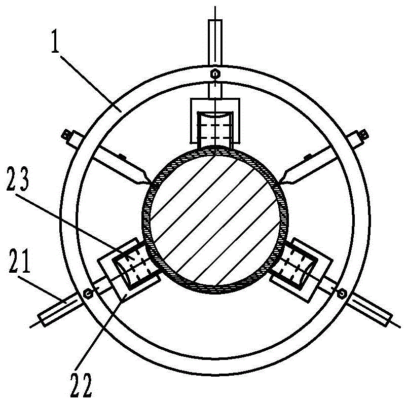
图1为本发明中切割刀具采用第一种调节固定组合切割绝缘层的正面结构示意图;1 is a schematic diagram of the front structure of the cutting tool in the present invention using the first adjusting and fixing combination to cut the insulating layer;
图2为本发明中切割刀具采用第二种调节固定组合切割绝缘层的正面结构示意图;2 is a schematic diagram of the front structure of the cutting tool in the present invention using the second type of adjusting and fixing combination to cut the insulating layer;
图3为本发明中剥离组件的工作状态结构示意图;3 is a schematic structural diagram of the working state of the peeling assembly in the present invention;
图4为本发明中第一种调节固定组合的结构示意放大图;4 is an enlarged schematic view of the structure of the first adjusting and fixing combination in the present invention;
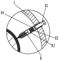
图5为本发明中第二种调节固定组合的结构示意放大图;5 is a schematic enlarged view of the structure of the second adjusting and fixing combination in the present invention;
图6为本发明中刀片设置并排双刃的结构示意图。FIG. 6 is a schematic structural diagram of a blade with side-by-side double-edged blades in the present invention.
具体实施方式Detailed ways
下面结合附图和实施例对本发明作进一步说明:Below in conjunction with accompanying drawing and embodiment, the present invention will be further described:
如图1、图2、图3、图4、图5以及图6所示,本发明公开了一种电缆绝缘层切割刀具,包括呈圆环形的刀体1,在刀体1的内环面上设有两个切割组件、一个剥离组件以及三个导向组件,三个导向组件沿刀体1的内环面周向均布设置,两个切割组件以其中任意一个导向组件为中心并对称设置于该导向组件的两侧。As shown in FIG. 1 , FIG. 2 , FIG. 3 , FIG. 4 , FIG. 5 and FIG. 6 , the present invention discloses a cable insulation layer cutting tool, comprising a circular-
每一个切割组件均包括有刀片8、刀架7以及调节固定组合,刀架7与刀体1通过螺栓固定连接,在刀架7内部开设有一个供刀片8滑动的滑槽,该滑槽的长方向与刀体1的径向一致。刀片8通过滑槽与刀架7滑动配合,刀片8的刀尖凸出于刀架7的外部,且刀尖朝向刀体1的回转中心,也即刀片8沿着滑槽的长方向滑动,实现刀尖与刀体1中心之间的距离发生变化,进而调整刀尖切入电缆绝缘层31的深度。Each cutting assembly includes a
调节固定组合设置于刀架7上,利用该调节固定组合实现刀片8与刀架7的固定连接、以及调节刀尖距离刀体1回转中心的相对距离。本案中给出了两种不同的调节固定组合:The adjusting and fixing combination is arranged on the
如图4所示的第一种调节固定组合:调节固定组合包括一颗调节螺栓61、一颗压紧螺钉62以及一块压片63,压紧螺钉62与刀架7螺纹连接,且该压紧螺钉62的远端与压片63转动连接;压片63位于滑槽内,且该压片63远离压紧螺钉62的侧面与刀片8贴合,利用该压片63与刀片8紧密贴合后实现刀片8与刀架7的固定;正向旋拧压紧螺钉62,压紧螺钉62向压片63施加正向压力,促使压片63对刀片8进行锁合,固定刀片8与滑槽的相对位置;而反向旋拧压紧螺钉62,则是松开刀片8,此时刀片8可以沿着滑槽的长度方向滑动;而对于调节螺栓61,调节螺栓61则是与刀架7螺纹配合,并且调节螺栓61的头部抵紧在刀片8的尾部,也即远离刀尖的一端。拧动调节螺栓61,可实现调节螺栓61向刀片8的尾部施加螺纹升力,进而促使刀片8沿着花草滑动,刀尖切入绝缘层31。As shown in Figure 4, the first adjustment and fixing combination: the adjustment and fixing combination includes an
如图5所示的第二种调节固定组合:包括调整螺栓81、压簧82和活塞体83,所述活塞体83与滑道滑动配合,该活塞体83与刀片8远离刀尖的尾部固定连接;压簧82处于压缩状态并设于滑道内,所述压簧82的一端与活塞体83抵接、另一端与刀体1抵接,利用该压簧82向活塞体83施加弹性压力,进而促使刀尖能够划破电缆的绝缘层31;该种调节固定组合时通过预设的压簧82压力,进而预设和限制了刀片8切入电缆绝缘层31的切割力,也即预设的压簧82压力=刀尖切割绝缘层31的切割力;这样设置的好处在于:使用时,不需要对刀尖与刀体1中心之间的距离进行调节,实施的是自动调节。而调整螺栓81则是与刀架7螺纹连接,同时调整螺栓81的头部通过一个圆柱形封堵块84与压簧82抵接,封堵块84与滑道滑动配合。调整螺栓81与调节螺栓61的安装方式相同,不同之处在于调整螺栓81用于调整压簧82的压缩值,也即最初的蓄能值。As shown in FIG. 5 , the second type of adjustment and fixation combination includes an
导向组件包括一根导向调节杆21、一个导向轮23以及一个轮架22,导向调节杆21沿刀体1的径向设置,且导向调节杆21与刀体1滑动配合并通过紧定螺钉进行定位和固定;轮架22固定安装在导向调节杆21靠近刀体1的回转中心的一端,导向轮23转动连接在轮架22上;导向轮23的回转轴线位于同一个平面上,并且所有导向轮23的滚动方向均与刀体1的中心回转轴线平行。The guide assembly includes a
剥离组件包括拉杆51以及挂钩52,拉杆51的一端与刀体1铰接、拉杆51的另一端与挂钩52固定连接。本优化的实施例中,挂钩52朝向拉杆51的侧面上设有倒刺52a。The peeling assembly includes a
需要说明的是,本优化的实施例中如图6所示,刀片8具有一个刀身,但是刀身的一侧设置有并排的两片刀刃81,每一片刀刃81均朝向刀体1的回转中心。下面以具体的实施方式以对本案的工作原理加以说明:It should be noted that, in this optimized embodiment, as shown in FIG. 6 , the
以图1和图2为例,电缆沿垂直于刀体1的方向插入刀体1中,然后刀体1沿电缆的长方向通过导向组件一直滚动至切割点。三个导向组件确定了一个共同的圆心,电缆的截面圆心与三个导向组件共同的圆心重合,此为定心。Taking Fig. 1 and Fig. 2 as an example, the cable is inserted into the
在该种切割模式下,如果采用的是第一种调节固定组合,那么在移动刀体1的时候,刀片8就已经对电缆的绝缘层31进行了切割;由于刀片8对绝缘层31施加的切割力是由压缩弹簧提供的,因此在出厂时,就设置了压缩弹簧多能提供给刀片8的切割力以及压缩弹簧的最大变形量,进而限制刀片8只能切割并划破结缘层,而无法划伤电缆的芯体32,进而使得电缆的芯体32得到保护。In this cutting mode, if the first adjustment and fixing combination is used, the
如果采取的是第二种调节固定组合,那么在移动刀体1的时候,可先调整刀片8与刀架7之间的相对位置,促使刀片8的刀尖先不与电缆的绝缘层31接触,而仅仅是三个导向组合与电缆的绝缘层31接触;待刀体1定位以后,再松动压紧螺钉62,压片63脱离刀片8,旋拧调节螺栓61,利用调节螺栓61调整刀尖切入电缆绝缘层31的深度,并维持刀片8切入电缆绝缘层31的深度小于电缆绝缘层31的厚度1mm~3mm左右,然后锁紧调节螺栓61以及压紧螺钉62,通过压紧螺钉62对刀片8进行锁紧;再向外拉动刀体1,刀体1在脱离电缆的时候,也即利用刀片8将绝缘体划破。If the second adjustment and fixation combination is adopted, then when moving the
上述两种使用方式,无论哪一种,均可以使用剥离组件对已经划破的绝缘体进行剥离。将剥离组件的挂钩52钩挂到绝缘层31上,拉动道题并在刀体1沿着电缆移动的同时,促使挂钩52可以将绝缘层31撕裂,并且挂钩52可以利用其上的倒刺52a牢固的够挂在绝缘层31上,进而防止挂钩52脱离绝缘层31。No matter which of the above two usage methods, the peeling assembly can be used to peel off the scratched insulator. The
需要说明的是,在前述是过程中,三个导向组合对电缆的定心非常重要,一方面控制刀体1与电缆之间的同心度不便宜,另一方面也属于稳定同心度的举措,因此本案中设置了三个导向组合。如果采用两个导向组合,可能会导致电缆在刀体1移动过程中脱离导向组合的导向轮23;如果采取四个,那么就可能出现其中任意两个或者三个导向组合的同心度出现偏差,进而使得刀片8切入绝缘层31的深度不稳定。It should be noted that in the aforementioned process, the three guide combinations are very important for the centering of the cable. On the one hand, it is not cheap to control the concentricity between the
而在本案中,采用了双切割组合的模式,并且两个切割组合对称设置。这样设置的好处在于,切割组合不仅能够完成对绝缘层31的切割,而且还能够进一步稳定电缆与三个导向组合之间的同心度,这样做到万无一失,进而避免刀片8将电缆的芯体32划伤。In this case, the pattern of double cutting combination is adopted, and the two cutting combinations are arranged symmetrically. The advantage of this arrangement is that the cutting combination can not only complete the cutting of the insulating
而在本优化方案中,将刀片8改造为设置并排的两片刀刃81的结构也是如此,进一步稳定电缆与三个导向组合之间的同心度,避免刀片8将电缆的芯体32划伤。In this optimized solution, the same is true for the structure of changing the
以上所述仅为本发明的较佳实施例而已,并不以本发明为限制,凡在本发明的精神和原则之内所作的任何修改、等同替换和改进等,均应包含在本发明的保护范围之内。The above descriptions are only preferred embodiments of the present invention, and are not intended to limit the present invention. Any modifications, equivalent replacements and improvements made within the spirit and principles of the present invention shall be included in the scope of the present invention. within the scope of protection.
Claims (6)
Priority Applications (1)
| Application Number | Priority Date | Filing Date | Title |
|---|---|---|---|
| CN202010274060.8A CN111355190A (en) | 2020-04-09 | 2020-04-09 | Cable insulation layer cutting tool |
Applications Claiming Priority (1)
| Application Number | Priority Date | Filing Date | Title |
|---|---|---|---|
| CN202010274060.8A CN111355190A (en) | 2020-04-09 | 2020-04-09 | Cable insulation layer cutting tool |
Publications (1)
| Publication Number | Publication Date |
|---|---|
| CN111355190A true CN111355190A (en) | 2020-06-30 |
Family
ID=71194884
Family Applications (1)
| Application Number | Title | Priority Date | Filing Date |
|---|---|---|---|
| CN202010274060.8A Pending CN111355190A (en) | 2020-04-09 | 2020-04-09 | Cable insulation layer cutting tool |
Country Status (1)
| Country | Link |
|---|---|
| CN (1) | CN111355190A (en) |
Cited By (8)
| Publication number | Priority date | Publication date | Assignee | Title |
|---|---|---|---|---|
| CN112260150A (en) * | 2020-10-26 | 2021-01-22 | 浙江一舟电子科技股份有限公司 | Cable stripping machine |
| CN112497273A (en) * | 2020-10-30 | 2021-03-16 | 何玉博 | Optical fiber splitting equipment suitable for different thicknesses and used for optical fiber recycling |
| CN112688241A (en) * | 2021-01-13 | 2021-04-20 | 国网冀北电力有限公司唐山供电公司 | Stripping device and method for high-voltage cable head |
| GB2606561A (en) * | 2021-05-13 | 2022-11-16 | Eco Live Systems Ltd | Method of safely accessing ducting pipes |
| CN115693529A (en) * | 2022-12-08 | 2023-02-03 | 云南电力试验研究院(集团)有限公司 | 35kV cable semi-conductive layer stripper and cable semi-conductive layer stripping method |
| CN115954806A (en) * | 2022-12-29 | 2023-04-11 | 常州市禾昌智能科技有限公司 | Automatic wire stripping machine is with line ball subassembly that has intelligent control module group |
| CN116061251A (en) * | 2023-01-31 | 2023-05-05 | 国网福建省电力有限公司 | A Reaction Force Cone Cutting Device and Working Method for 10kV Cable Main Insulation Layer of Distribution Network |
| CN116231540A (en) * | 2023-01-31 | 2023-06-06 | 国网福建省电力有限公司 | A reaction force cone treatment process and cutting device for the main insulation layer of 10kV cables in distribution network |
Citations (7)
| Publication number | Priority date | Publication date | Assignee | Title |
|---|---|---|---|---|
| US5230260A (en) * | 1992-09-08 | 1993-07-27 | Bell James R | Tool for stripping cable insulation and method |
| CN201393018Y (en) * | 2009-04-23 | 2010-01-27 | 山东电力集团公司济南供电公司 | Cable Stripping Knife |
| CN102035153A (en) * | 2009-09-25 | 2011-04-27 | 王顺年 | Peeling blade on intermediate peeler for 24KV insulated cable |
| CN201829869U (en) * | 2010-10-22 | 2011-05-11 | 衡水供电公司 | Stripper for cable |
| CN103219677A (en) * | 2013-04-27 | 2013-07-24 | 乌云其劳 | Sheath stripping cutter of cable |
| CN104124649A (en) * | 2014-08-14 | 2014-10-29 | 国家电网公司 | Cable stripping tool |
| CN104485612A (en) * | 2014-12-10 | 2015-04-01 | 国家电网公司 | Wire stripper |
-
2020
- 2020-04-09 CN CN202010274060.8A patent/CN111355190A/en active Pending
Patent Citations (7)
| Publication number | Priority date | Publication date | Assignee | Title |
|---|---|---|---|---|
| US5230260A (en) * | 1992-09-08 | 1993-07-27 | Bell James R | Tool for stripping cable insulation and method |
| CN201393018Y (en) * | 2009-04-23 | 2010-01-27 | 山东电力集团公司济南供电公司 | Cable Stripping Knife |
| CN102035153A (en) * | 2009-09-25 | 2011-04-27 | 王顺年 | Peeling blade on intermediate peeler for 24KV insulated cable |
| CN201829869U (en) * | 2010-10-22 | 2011-05-11 | 衡水供电公司 | Stripper for cable |
| CN103219677A (en) * | 2013-04-27 | 2013-07-24 | 乌云其劳 | Sheath stripping cutter of cable |
| CN104124649A (en) * | 2014-08-14 | 2014-10-29 | 国家电网公司 | Cable stripping tool |
| CN104485612A (en) * | 2014-12-10 | 2015-04-01 | 国家电网公司 | Wire stripper |
Cited By (11)
| Publication number | Priority date | Publication date | Assignee | Title |
|---|---|---|---|---|
| CN112260150A (en) * | 2020-10-26 | 2021-01-22 | 浙江一舟电子科技股份有限公司 | Cable stripping machine |
| CN112497273A (en) * | 2020-10-30 | 2021-03-16 | 何玉博 | Optical fiber splitting equipment suitable for different thicknesses and used for optical fiber recycling |
| CN112688241A (en) * | 2021-01-13 | 2021-04-20 | 国网冀北电力有限公司唐山供电公司 | Stripping device and method for high-voltage cable head |
| CN112688241B (en) * | 2021-01-13 | 2022-05-20 | 国网冀北电力有限公司唐山供电公司 | High-voltage cable head stripping device and method |
| GB2606561A (en) * | 2021-05-13 | 2022-11-16 | Eco Live Systems Ltd | Method of safely accessing ducting pipes |
| CN115693529A (en) * | 2022-12-08 | 2023-02-03 | 云南电力试验研究院(集团)有限公司 | 35kV cable semi-conductive layer stripper and cable semi-conductive layer stripping method |
| CN115954806A (en) * | 2022-12-29 | 2023-04-11 | 常州市禾昌智能科技有限公司 | Automatic wire stripping machine is with line ball subassembly that has intelligent control module group |
| CN115954806B (en) * | 2022-12-29 | 2023-12-29 | 常州市禾昌智能科技有限公司 | Wire pressing assembly with intelligent control module for automatic wire stripping machine |
| CN116061251A (en) * | 2023-01-31 | 2023-05-05 | 国网福建省电力有限公司 | A Reaction Force Cone Cutting Device and Working Method for 10kV Cable Main Insulation Layer of Distribution Network |
| CN116231540A (en) * | 2023-01-31 | 2023-06-06 | 国网福建省电力有限公司 | A reaction force cone treatment process and cutting device for the main insulation layer of 10kV cables in distribution network |
| CN116231540B (en) * | 2023-01-31 | 2025-11-21 | 国网福建省电力有限公司 | Processing technology and cutting device for reactive power cone of main insulation layer of distribution network 10kV cable |
Similar Documents
| Publication | Publication Date | Title |
|---|---|---|
| CN101554697B (en) | Improve thread machining device of steel bar joint resistance to deformation ability | |
| CN204089063U (en) | A kind of novel cable bark knife | |
| CN204030463U (en) | The special wire stripper of a kind of cable | |
| CN209150620U (en) | A tool for stripping protective cable skin | |
| CN113839350A (en) | Slitting assembly and automatic wire stripping device | |
| CN105958391A (en) | Screw type cable circumferential peeling tool and peeling method thereof | |
| CN112260150B (en) | Cable stripper | |
| CN207320723U (en) | Cable peeling knife | |
| CN102208781A (en) | Efficient stripping and cutting pliers for insulating layer of crosslinked power cable | |
| CN203434537U (en) | Cable stripper | |
| CN114824994A (en) | Cable stripping method | |
| CN212543220U (en) | Cable sheath wire stripping device | |
| CN204424812U (en) | A kind of cable sheath cutting tool being convenient to regulate | |
| CN216056062U (en) | Slitting assembly and automatic wire stripping device | |
| CN201327968Y (en) | Peeling and cutting tool for external semi-conductive layer of power cable | |
| CN107732799B (en) | A cable steel armor cutting machine | |
| CN216598765U (en) | Electric mould-changing-free insulated cable stripper | |
| CN203932853U (en) | 10kV cable outer semiconducting layer Combined knife | |
| CN204271544U (en) | A kind of guide colume type self centring flexible cable compound slide | |
| CN104600631B (en) | A kind of cable sheath electric cutting tool | |
| CN109904795B (en) | A wire stripper | |
| CN111055325B (en) | Angular incision device and method for nonmetal ring | |
| CN206225908U (en) | Cable sheath circular cutter | |
| CN202684988U (en) | Hole cutting device for power busbar heat-shrinkable tube | |
| CN201994603U (en) | Wire stripper for crosslinked power cable |
Legal Events
| Date | Code | Title | Description |
|---|---|---|---|
| PB01 | Publication | ||
| PB01 | Publication | ||
| SE01 | Entry into force of request for substantive examination | ||
| SE01 | Entry into force of request for substantive examination | ||
| RJ01 | Rejection of invention patent application after publication | ||
| RJ01 | Rejection of invention patent application after publication |
Application publication date: 20200630 |