CN111352369A - Electric automatization control cabinet - Google Patents
Electric automatization control cabinet Download PDFInfo
- Publication number
- CN111352369A CN111352369A CN202010181158.9A CN202010181158A CN111352369A CN 111352369 A CN111352369 A CN 111352369A CN 202010181158 A CN202010181158 A CN 202010181158A CN 111352369 A CN111352369 A CN 111352369A
- Authority
- CN
- China
- Prior art keywords
- cabinet body
- fixed mounting
- driving motor
- fixedly installed
- display screen
- Prior art date
- Legal status (The legal status is an assumption and is not a legal conclusion. Google has not performed a legal analysis and makes no representation as to the accuracy of the status listed.)
- Pending
Links
Images


Classifications
-
- G—PHYSICS
- G05—CONTROLLING; REGULATING
- G05B—CONTROL OR REGULATING SYSTEMS IN GENERAL; FUNCTIONAL ELEMENTS OF SUCH SYSTEMS; MONITORING OR TESTING ARRANGEMENTS FOR SUCH SYSTEMS OR ELEMENTS
- G05B19/00—Program-control systems
- G05B19/02—Program-control systems electric
- G05B19/04—Program control other than numerical control, i.e. in sequence controllers or logic controllers
- G05B19/042—Program control other than numerical control, i.e. in sequence controllers or logic controllers using digital processors
-
- H—ELECTRICITY
- H05—ELECTRIC TECHNIQUES NOT OTHERWISE PROVIDED FOR
- H05K—PRINTED CIRCUITS; CASINGS OR CONSTRUCTIONAL DETAILS OF ELECTRIC APPARATUS; MANUFACTURE OF ASSEMBLAGES OF ELECTRICAL COMPONENTS
- H05K7/00—Constructional details common to different types of electric apparatus
- H05K7/20—Modifications to facilitate cooling, ventilating, or heating
- H05K7/20009—Modifications to facilitate cooling, ventilating, or heating using a gaseous coolant in electronic enclosures
- H05K7/20136—Forced ventilation, e.g. by fans
Landscapes
- Engineering & Computer Science (AREA)
- Microelectronics & Electronic Packaging (AREA)
- Physics & Mathematics (AREA)
- Thermal Sciences (AREA)
- General Physics & Mathematics (AREA)
- Automation & Control Theory (AREA)
- Casings For Electric Apparatus (AREA)
Abstract
The invention discloses an electric automation console, which comprises a cabinet body, an operation panel and a display screen, wherein the operation panel is fixedly installed at the top of the cabinet body, a first sliding groove is formed in one side of the inner wall of the cabinet body, a first sliding block is connected inside the first sliding groove in a sliding mode, a lifting plate is fixedly installed on one side of the first sliding block, a supporting seat is fixedly installed at the bottom of the inner wall of the cabinet body, and a first driving motor is fixedly installed at the top of the supporting seat. This electric automatization control cabinet, the display screen can go up and down automatically, need carry out the fingerprint matching before the use, the fingerprint matches successfully the back, and the display screen on the control cabinet can stretch out automatically, if the fingerprint does not match, the display screen then can't stretch out, has improved the security of control cabinet, has avoided the non-relevant personnel to operate the control cabinet, does not use the control cabinet simultaneously, places the display screen in the inside of the cabinet body, can carry out fine protection to the display screen.
Description
Technical Field
The invention relates to the technical field of electrical equipment, in particular to an electrical automation console.
Background
Electricity is a generic term in the disciplines or engineering fields of production, transmission, distribution, use, and manufacture of electrical equipment for electrical energy. The electric automation control console is designed and manufactured according to special human engineering in a control room for running key tasks, and provides professional furniture capable of bearing various office equipment and special equipment for operating and dispatching personnel, wherein in the electric operation, the electric automation control console is a command center, but the existing electric automation control console has the following defects:
1. the existing console display screen is fixedly arranged on a console, after the console is used for a long time, a lot of scratches are generated on the display screen, particularly, the display screen is still exposed outside when not used, the display screen is easily accidentally damaged again, meanwhile, the console is not high in safety, and non-related personnel can operate the console, so that the management is not standard, and serious consequences can be caused;
2. when the console is used, the heat dissipation device in the console can always dissipate heat of the host, and when the heat dissipation device works without clearance for a long time, the heat dissipation device is easy to damage and can generate continuous noise to influence the work of workers;
3. the host computer of control cabinet is inside fixed mounting at the control cabinet, when needing to maintain the host computer, can't pull out the host computer to the trouble of maintaining the host computer ten minutes in narrow and small space.
Disclosure of Invention
Aiming at the defects of the prior art, the invention provides an electric automation console, and solves the problems that the safety of the conventional electric automation console is not high, a display screen is not well protected, a heat dissipation device is easy to damage and continuously work, and a host is troublesome to maintain.
In order to achieve the purpose, the invention is realized by the following technical scheme: an electric automation console comprises a cabinet body, an operation panel and a display screen, wherein the operation panel is fixedly arranged at the top of the cabinet body, a first sliding groove is arranged on one side of the inner wall of the cabinet body, a first sliding block is connected inside the first sliding groove in a sliding manner, and one side of the first slide block is fixedly provided with a lifting plate, the bottom of the inner wall of the cabinet body is fixedly provided with a supporting seat, the top of the supporting seat is fixedly provided with a first driving motor, and the output shaft of the first driving motor is fixedly provided with a first driving motor, the output shaft of the first driving motor is fixedly provided with a gear disc, the side surface of the lifting plate is fixedly provided with teeth matched with the gear disc for use, the top of the lifting plate is fixedly provided with a linkage plate, the display screen is fixedly installed at the top of the linkage plate, and an opening matched with the display screen for use is formed in the top of the cabinet body.
Preferably, a second sliding groove is formed in the bottom of the inner cavity of the cabinet body, a second sliding block is connected to the inner portion of the second sliding groove in a sliding mode, a supporting frame is fixedly mounted at the top of the second sliding block, and a host is fixedly mounted on one side of the top of the supporting frame.
Preferably, the opposite side fixed mounting at carriage top has the mounting panel, the side fixed mounting of mounting panel has second driving motor to second driving motor's output shaft fixed mounting has power gear, the upper portion and the lower part of mounting panel side all are connected with the dwang through the bearing rotation, and the one end fixed mounting of dwang has the heat dissipation flabellum.
Preferably, the fixed surface of dwang has driven gear, mesh between driven gear and the power gear mutually, the bottom of carriage rotates through rotating and is connected with electric telescopic handle to electric telescopic handle's one end fixed mounting has supporting pulley.
Preferably, the side of the supporting frame is bonded with a sealing strip, and handles are fixedly mounted on two sides of the surface of the supporting frame.
Preferably, one side fixed mounting at cabinet body inner chamber top has the control box to one side fixed mounting of control box inner chamber has the battery, the embedded opposite side fixed mounting of control box has central processing unit, cabinet body inner chamber's top fixed mounting has temperature sensor, one side fixed mounting on cabinet body surface has the control button, the top fixed mounting that just is located the control button on the surface of the cabinet body has fingerprint identification ware.
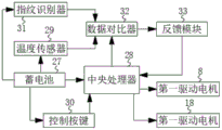
Preferably, the output ends of the fingerprint identifier and the temperature sensor are connected with the input end of the data comparator, the output end of the data comparator is connected with the input end of the feedback module, the output end of the feedback module is connected with the input end of the central processing unit, and the output end of the central processing unit is respectively connected with the input ends of the data comparator, the first driving motor and the second driving motor.
Preferably, the output end of the storage battery is respectively and electrically connected with the input ends of the fingerprint identifier, the temperature sensor, the central processing unit and the control key, and the output end of the control key is connected with the input end of the central processing unit.
Preferably, four corners of the bottom of the cabinet body are fixedly provided with universal wheels, and the side surface of the cabinet body is provided with a heat dissipation window.
Advantageous effects
The invention provides an electric automation console. Compared with the prior art, the method has the following beneficial effects:
(1) the electric automation console is connected with a first sliding block through the inside of a first sliding chute in a sliding manner, a lifting plate is fixedly arranged on one side of the first sliding block, a supporting seat is fixedly arranged at the bottom of the inner wall of a cabinet body, a first driving motor is fixedly arranged at the top of the supporting seat, a first driving motor is fixedly arranged on an output shaft of the first driving motor, a gear disc is fixedly arranged on the output shaft of the first driving motor, teeth matched with the gear disc for use are fixedly arranged on the side surface of the lifting plate, a linkage plate is fixedly arranged at the top of the lifting plate, a display screen is fixedly arranged at the top of the linkage plate, an opening matched with the display screen for use is formed in the top of the cabinet body, the output ends of a fingerprint recognizer and a temperature sensor are both connected with the input end of a data comparator, the output end of the data comparator is connected with the input end, central processing unit's output respectively with the data contrast ware, first driving motor be connected with the second driving motor input, the display screen can go up and down automatically, need carry out the fingerprint matching before the use, the fingerprint matches successfully the back, display screen on the control cabinet can stretch out automatically, if the fingerprint does not match, the display screen then can't stretch out, the security of control cabinet has been improved, the irrelevant personnel of having avoided operate the control cabinet, the control cabinet is not being used simultaneously, place the inside at the cabinet body with the display screen, can carry out fine protection to the display screen.
(2) The electric automation console is fixedly provided with a mounting plate through the other side of the top of a supporting frame, the side surface of the mounting plate is fixedly provided with a second driving motor, an output shaft of the second driving motor is fixedly provided with a power gear, the upper part and the lower part of the side surface of the mounting plate are both rotatably connected with a rotating rod through bearings, one end of the rotating rod is fixedly provided with a radiating fan blade, the output ends of a fingerprint recognizer and a temperature sensor are both connected with the input end of a data comparator, the output end of the data comparator is connected with the input end of a feedback module, the output end of the feedback module is connected with the input end of a central processing unit, the output end of the central processing unit is respectively connected with the data comparator, the input end of a first driving motor and the input end of a second driving motor, when the console is used, the, inside heat abstractor can the automatic start, and after the temperature is up to standard, heat abstractor can self-closing, has avoided heat abstractor to last for a long time and has carried out work, adopts two radiator fin to dispel the heat simultaneously, has improved the radiating efficiency.
(3) This electric automatization control cabinet, the second spout has been seted up through cabinet body inner chamber's bottom, and the inside sliding connection of second spout has the second slider, the top fixed mounting of second slider has the carriage, one side fixed mounting at carriage top has the host computer, the bottom of carriage rotates through rotating and is connected with electric telescopic handle, and electric telescopic handle's one end fixed mounting has a supporting pulley, become mobilizable formula with the host computer design, when needs maintain the host computer, can be quick pull out the host computer, thereby the convenience is maintained the host computer, and work efficiency is improved.
Drawings
FIG. 1 is a schematic structural view of the present invention;
FIG. 2 is a cross-sectional view of the cabinet structure of the present invention;
FIG. 3 is a side view of the first drive motor and gear plate arrangement of the present invention;
FIG. 4 is an enlarged view of a portion of the invention at A in FIG. 2;
FIG. 5 is a cross-sectional view of the control box structure of the present invention;
fig. 6 is a schematic block diagram of the architecture of the system of the present invention.
In the figure: 1. a cabinet body; 2. an operation panel; 3. a display screen; 4. a first chute; 5. a first slider; 6. A lifting plate; 7. a supporting seat; 8. a first drive motor; 9. a gear plate; 10. teeth; 11. a linkage plate; 12. an opening; 13. a second chute; 14. a second slider; 15. a support frame; 16. a host; 17. Mounting a plate; 18. a second drive motor; 19. a power gear; 20. rotating the rod; 21. a heat dissipation fan blade; 22. a driven gear; 23. a support pulley; 24. a sealing strip; 25. a handle; 26. a control box; 27. A storage battery; 28. a central processing unit; 29. a temperature sensor; 30. a control key; 31. a fingerprint identifier; 32. a data comparator; 33. a feedback module; 34. a universal wheel; 35. a heat dissipation window; 36. an electric telescopic rod.
Detailed Description
The technical solutions in the embodiments of the present invention will be clearly and completely described below with reference to the drawings in the embodiments of the present invention, and it is obvious that the described embodiments are only a part of the embodiments of the present invention, and not all of the embodiments. All other embodiments, which can be derived by a person skilled in the art from the embodiments given herein without making any creative effort, shall fall within the protection scope of the present invention.
Referring to fig. 1-6, the present invention provides a technical solution: an electric automation console comprises a cabinet body 1, an operation panel 2 and a display screen 3, wherein the operation panel 2 is fixedly arranged at the top of the cabinet body 1, one side of the inner wall of the cabinet body 1 is provided with a first chute 4, the inside of the first chute 4 is connected with a first slide block 5 in a sliding way, and one side of the first slide block 5 is fixedly provided with a lifting plate 6, the bottom of the inner wall of the cabinet body 1 is fixedly provided with a supporting seat 7, the top of the supporting seat 7 is fixedly provided with a first driving motor 8, and the output shaft of the first driving motor 8 is fixedly provided with the first driving motor 8, the output shaft of the first driving motor 8 is fixedly provided with the gear disc 9, the side surface of the lifting plate 6 is fixedly provided with teeth 10 matched with the gear disc 9 for use, the top of the lifting plate 6 is fixedly provided with the linkage plate 11, the display screen 3 is fixedly arranged at the top of the linkage plate 11, and the top of the cabinet body 1 is provided with an opening 12 matched with the display screen 3 for use.
In the invention, the bottom of the inner cavity of the cabinet body 1 is provided with a second chute 13, the inside of the second chute 13 is connected with a second sliding block 14 in a sliding manner, the top of the second sliding block 14 is fixedly provided with a supporting frame 15, and one side of the top of the supporting frame 15 is fixedly provided with a host computer 16.
In the invention, an installation plate 17 is fixedly installed on the other side of the top of the supporting frame 15, a second driving motor 18 is fixedly installed on the side surface of the installation plate 17, the first driving motor 8 and the second driving motor 18 are both servo motors, a power gear 19 is fixedly installed on an output shaft of the second driving motor 18, the upper part and the lower part of the side surface of the installation plate 17 are both rotatably connected with a rotating rod 20 through a bearing, and a heat radiation fan blade 21 is fixedly installed at one end of the rotating rod 20.
In the invention, the driven gear 22 is fixedly arranged on the surface of the rotating rod 20, the driven gear 22 is meshed with the power gear 19, the bottom of the supporting frame 15 is rotatably connected with the electric telescopic rod 36 through a rotating part, the supporting pulley 23 is fixedly arranged at one end of the electric telescopic rod 36, and two sides of the bottom of the surface of the cabinet body 1 are provided with grooves for pulling out the electric telescopic rod 36 and the supporting pulley 23.
In the invention, the side edge of the supporting frame 15 is bonded with the sealing strip 24, the sealing strip 24 is made of rubber and has good sealing property, and the two sides of the surface of the supporting frame 15 are both fixedly provided with the handles 25.
In the invention, a control box 26 is fixedly arranged on one side of the top of an inner cavity of a cabinet body 1, a storage battery 27 is fixedly arranged on one side of the inner cavity of the control box 26, a central processing unit 28 is fixedly arranged on the other side embedded in the control box 26, the model of the central processing unit 28 is ARM9, a temperature sensor 29 is fixedly arranged on the top of the inner cavity of the cabinet body 1, the model of the temperature sensor 29 is DS18B20, a control key 30 is fixedly arranged on one side of the surface of the cabinet body 1, a fingerprint identifier 31 is fixedly arranged on the surface of the cabinet body 1 and above the control key 30, and the fingerprint identifier 31 is mainly.
In the invention, the output ends of the fingerprint identifier 31 and the temperature sensor 29 are both connected with the input end of the data comparator 32, the output end of the data comparator 32 is connected with the input end of the feedback module 33, the output end of the feedback module 33 is connected with the input end of the central processor 28, and the output end of the central processor 28 is respectively connected with the data comparator 32, the input end of the first driving motor 8 and the input end of the second driving motor 18.
In the present invention, the output terminal of the battery 27 is electrically connected to the input terminals of the fingerprint identifier 31, the temperature sensor 29, the central processing unit 28 and the control key 30, respectively, and the output terminal of the control key 30 is connected to the input terminal of the central processing unit 28.
In the invention, universal wheels 34 are fixedly arranged at four corners of the bottom of the cabinet body 1, and a heat radiation window 35 is arranged on the side surface of the cabinet body 1.
And those not described in detail in this specification are well within the skill of those in the art.
Before using, operating personnel can be through control button 30 to central processing unit 28 input normal temperature value, as the normal value of the internal temperature of cabinet 1, temperature sensor 29 can detect the temperature value in the cabinet 1, as the detected value, and the user can input the fingerprint to central processing unit 28 through control button 30 and fingerprint identification ware 31 simultaneously, and as standard fingerprint, fingerprint identification ware 31 can detect user's fingerprint, as detecting fingerprint
When the intelligent control cabinet is used, if an operator needs to use the control cabinet, the operator can place a finger on the fingerprint identifier 31, the fingerprint identifier 31 can send the fingerprint of the operator to the data comparator 32, the data comparator 32 can transmit the fingerprint of the user to the central processing unit 28 through the feedback module 33, a standard fingerprint arranged through the control key 30 and the fingerprint identifier 31 before use can be transmitted to the data comparator 32 through the central processing unit 28, when the standard fingerprint is matched with a detected fingerprint, the central processing unit 28 can start the first driving motor 8, the output shaft of the first driving motor 8 can drive the gear disc 9 to rotate, the gear disc 9 can drive the lifting plate 6 to move upwards through the teeth 10, the lifting plate 6 can drive the display screen 3 to move upwards through the linkage plate 11, so that the display screen 3 extends out of the cabinet body 1, at the moment, the operator can operate the control cabinet by watching the display screen 3 and controlling the operation panel 2, after the use, the display screen 3 can be reset to the inside of the console through the control key 30, when the console normally operates, the temperature sensor 29 can transmit the real-time temperature in the cabinet body 1 to the data comparator 32, the data comparator 32 can transmit the temperature value to the central processing unit 28 through the feedback module 33, the normal value set through the control key 30 before the use can be transmitted to the data comparator 32 through the central processing unit 28, when the detection value is greater than the normal value, the central processing unit 28 can start the second driving motor 18, the output shaft of the second driving motor 18 can drive the power gear 19 to rotate, the power gear 19 can drive the rotating rod 20 to rotate through the driven gear 22, the rotating rod 20 can drive the heat dissipation fan blades 21 to rotate, thereby dissipating heat from the host computer 16, when the host computer 16 needs to be maintained, an operator can pull the support frame 15 outwards through the handle 25, thereby pull out host computer 16 on the carriage 15, operating personnel can rotate 90 degrees with electric telescopic handle 36 this moment for electric telescopic handle 36 is perpendicular with ground, opens electric telescopic handle 36 this moment, makes supporting pulley 23 and ground contact, thereby can carry out stable support to carriage 15.
It is noted that, herein, relational terms such as second and third, and the like may be used solely to distinguish one entity or action from another entity or action without necessarily requiring or implying any actual such relationship or order between such entities or actions. Also, the terms "comprises," "comprising," or any other variation thereof, are intended to cover a non-exclusive inclusion, such that a process, method, article, or apparatus that comprises a list of elements does not include only those elements but may include other elements not expressly listed or inherent to such process, method, article, or apparatus.
Although embodiments of the present invention have been shown and described, it will be appreciated by those skilled in the art that changes, modifications, substitutions and alterations can be made in these embodiments without departing from the principles and spirit of the invention, the scope of which is defined in the appended claims and their equivalents.
Claims (9)
1. The utility model provides an electric automation control platform, includes the cabinet body (1), operating panel (2) and display screen (3), operating panel (2) fixed mounting is in the top of the cabinet body (1), its characterized in that: a first sliding chute (4) is formed in one side of the inner wall of the cabinet body (1), a first sliding block (5) is connected to the inside of the first sliding chute (4) in a sliding mode, a lifting plate (6) is fixedly installed on one side of the first sliding block (5), a supporting seat (7) is fixedly installed at the bottom of the inner wall of the cabinet body (1), a first driving motor (8) is fixedly installed at the top of the supporting seat (7), a first driving motor (8) is fixedly installed on an output shaft of the first driving motor (8), a gear disc (9) is fixedly installed on an output shaft of the first driving motor (8), teeth (10) matched with the gear disc (9) for use are fixedly installed on the side face of the lifting plate (6), a linkage plate (11) is fixedly installed at the top of the lifting plate (6), and the display screen (3) is fixedly installed at the top of the linkage plate (, the top of the cabinet body (1) is provided with an opening (12) matched with the display screen (3) for use.
2. An electrical automation console as in claim 1 wherein: second spout (13) have been seted up to the bottom of the cabinet body (1) inner chamber to the inside sliding connection of second spout (13) has second slider (14), the top fixed mounting of second slider (14) has carriage (15), one side fixed mounting at carriage (15) top has host computer (16).
3. An electrical automation console as in claim 2 wherein: the opposite side fixed mounting at carriage (15) top has mounting panel (17), the side fixed mounting of mounting panel (17) has second driving motor (18) to the output shaft fixed mounting of second driving motor (18) has power gear (19), the upper portion and the lower part of mounting panel (17) side all are connected with dwang (20) through the bearing rotation, and the one end fixed mounting of dwang (20) has heat dissipation flabellum (21).
4. An electrical automation console as in claim 3 wherein: the fixed surface of dwang (20) installs driven gear (22), mesh mutually between driven gear (22) and power gear (19), the bottom of carriage (15) is rotated through rotating and is connected with electric telescopic handle (36) to the one end fixed mounting of electric telescopic handle (36) has supporting pulley (23).
5. An electrical automation console as in claim 2 wherein: the side of carriage (15) is glued has sealing strip (24), the equal fixed mounting in both sides on carriage (15) surface has handle (25).
6. An electrical automation console as in claim 1 wherein: the utility model discloses a cabinet body, including the cabinet body, one side fixed mounting at cabinet body (1) inner chamber top has control box (26) to one side fixed mounting of control box (26) inner chamber has battery (27), embedded opposite side fixed mounting of control box (26) has central processing unit (28), the top fixed mounting of the cabinet body (1) inner chamber has temperature sensor (29), one side fixed mounting on the cabinet body (1) surface has control button (30), the top fixed mounting that just is located control button (30) on the surface of the cabinet body (1) has fingerprint identification ware (31).
7. An electrical automation console as in claim 6 wherein: the output of fingerprint identification ware (31) and temperature sensor (29) all is connected with the input of data contrast ware (32), the output of data contrast ware (32) is connected with the input of feedback module (33), the output of feedback module (33) is connected with the input of central processing unit (28), the output of central processing unit (28) respectively with data contrast ware (32), first driving motor (8) with second driving motor (18) input be connected.
8. An electrical automation console as in claim 7 wherein: the output end of the storage battery (27) is electrically connected with the input ends of the fingerprint identifier (31), the temperature sensor (29), the central processing unit (28) and the control key (30), and the output end of the control key (30) is connected with the input end of the central processing unit (28).
9. An electrical automation console as in claim 1 wherein: the four corners of the bottom of the cabinet body (1) are fixedly provided with universal wheels (34), and the side surface of the cabinet body (1) is provided with a heat dissipation window (35).
Priority Applications (1)
| Application Number | Priority Date | Filing Date | Title |
|---|---|---|---|
| CN202010181158.9A CN111352369A (en) | 2020-03-16 | 2020-03-16 | Electric automatization control cabinet |
Applications Claiming Priority (1)
| Application Number | Priority Date | Filing Date | Title |
|---|---|---|---|
| CN202010181158.9A CN111352369A (en) | 2020-03-16 | 2020-03-16 | Electric automatization control cabinet |
Publications (1)
| Publication Number | Publication Date |
|---|---|
| CN111352369A true CN111352369A (en) | 2020-06-30 |
Family
ID=71194726
Family Applications (1)
| Application Number | Title | Priority Date | Filing Date |
|---|---|---|---|
| CN202010181158.9A Pending CN111352369A (en) | 2020-03-16 | 2020-03-16 | Electric automatization control cabinet |
Country Status (1)
| Country | Link |
|---|---|
| CN (1) | CN111352369A (en) |
Cited By (5)
| Publication number | Priority date | Publication date | Assignee | Title |
|---|---|---|---|---|
| CN112085978A (en) * | 2020-09-27 | 2020-12-15 | 上海多语文化科技有限公司 | Foreign language training display service system |
| CN112203451A (en) * | 2020-09-15 | 2021-01-08 | 绍兴盈顺机电科技有限公司 | Control cabinet for electromechanical device |
| CN112654181A (en) * | 2020-09-14 | 2021-04-13 | 泰州市银杏舞台机械工程有限公司 | Stage jib control cabinet device |
| CN113365445A (en) * | 2021-06-07 | 2021-09-07 | 宁波金智源科技服务有限公司 | ERP-based office user-defined flow intelligent management system and device |
| CN114449811A (en) * | 2022-02-08 | 2022-05-06 | 江苏盈达机电科技有限公司 | Main control table convenient to adjust for refrigerating unit |
Citations (8)
| Publication number | Priority date | Publication date | Assignee | Title |
|---|---|---|---|---|
| CN206061323U (en) * | 2016-09-06 | 2017-03-29 | 深圳市国立旭振电气技术有限公司 | A kind of 1 electromotor Automated condtrol cabinets of GLZD |
| CN206275370U (en) * | 2016-10-09 | 2017-06-27 | 大道网络(上海)股份有限公司 | A kind of computer mainframe cabinet for console |
| CN207555138U (en) * | 2017-12-15 | 2018-06-29 | 江西亿康云谷自动化设备有限公司 | A kind of liquid crystal screen lifting machine cabinet |
| CN109149402A (en) * | 2018-08-30 | 2019-01-04 | 天津市远叶科技有限公司 | A kind of control cabinet used for wind power generation easy to repair |
| CN109907497A (en) * | 2019-01-18 | 2019-06-21 | 杭州志远科技有限公司 | A kind of data visualization control device of large-scale experiment room |
| CN110121247A (en) * | 2019-04-12 | 2019-08-13 | 珠海市扬铵机电设备安装工程有限公司 | A kind of Intelligent control cabinet |
| KR102014436B1 (en) * | 2018-04-30 | 2019-08-26 | 전남대학교 산학협력단 | Hair Dryer Having Detailed Control for Wind-Strength and Temperature |
| CN209964442U (en) * | 2019-04-04 | 2020-01-17 | 董洵佚 | Electrical equipment automation control cabinet |
-
2020
- 2020-03-16 CN CN202010181158.9A patent/CN111352369A/en active Pending
Patent Citations (8)
| Publication number | Priority date | Publication date | Assignee | Title |
|---|---|---|---|---|
| CN206061323U (en) * | 2016-09-06 | 2017-03-29 | 深圳市国立旭振电气技术有限公司 | A kind of 1 electromotor Automated condtrol cabinets of GLZD |
| CN206275370U (en) * | 2016-10-09 | 2017-06-27 | 大道网络(上海)股份有限公司 | A kind of computer mainframe cabinet for console |
| CN207555138U (en) * | 2017-12-15 | 2018-06-29 | 江西亿康云谷自动化设备有限公司 | A kind of liquid crystal screen lifting machine cabinet |
| KR102014436B1 (en) * | 2018-04-30 | 2019-08-26 | 전남대학교 산학협력단 | Hair Dryer Having Detailed Control for Wind-Strength and Temperature |
| CN109149402A (en) * | 2018-08-30 | 2019-01-04 | 天津市远叶科技有限公司 | A kind of control cabinet used for wind power generation easy to repair |
| CN109907497A (en) * | 2019-01-18 | 2019-06-21 | 杭州志远科技有限公司 | A kind of data visualization control device of large-scale experiment room |
| CN209964442U (en) * | 2019-04-04 | 2020-01-17 | 董洵佚 | Electrical equipment automation control cabinet |
| CN110121247A (en) * | 2019-04-12 | 2019-08-13 | 珠海市扬铵机电设备安装工程有限公司 | A kind of Intelligent control cabinet |
Cited By (6)
| Publication number | Priority date | Publication date | Assignee | Title |
|---|---|---|---|---|
| CN112654181A (en) * | 2020-09-14 | 2021-04-13 | 泰州市银杏舞台机械工程有限公司 | Stage jib control cabinet device |
| CN112203451A (en) * | 2020-09-15 | 2021-01-08 | 绍兴盈顺机电科技有限公司 | Control cabinet for electromechanical device |
| CN112085978A (en) * | 2020-09-27 | 2020-12-15 | 上海多语文化科技有限公司 | Foreign language training display service system |
| CN113365445A (en) * | 2021-06-07 | 2021-09-07 | 宁波金智源科技服务有限公司 | ERP-based office user-defined flow intelligent management system and device |
| CN114449811A (en) * | 2022-02-08 | 2022-05-06 | 江苏盈达机电科技有限公司 | Main control table convenient to adjust for refrigerating unit |
| CN114449811B (en) * | 2022-02-08 | 2023-11-28 | 江苏盈达机电科技有限公司 | Main control desk convenient to adjust for refrigerating unit |
Similar Documents
| Publication | Publication Date | Title |
|---|---|---|
| CN205489184U (en) | Dustproof electric power power distribution control case | |
| CN211428622U (en) | A mobile power distribution cabinet for easy maintenance | |
| CN206506203U (en) | A kind of low-voltage electrical element pull-out type installs switch cubicle | |
| CN109861092B (en) | Dustproof ventilation type switch board | |
| CN212749574U (en) | A cab console with ventilation and heat dissipation | |
| CN211577838U (en) | Computer hardware heat dissipation mechanism | |
| CN210244917U (en) | Heat dissipation device of outdoor LED display screen | |
| CN220285424U (en) | Movable property security duty pavilion | |
| CN216720714U (en) | Low-voltage distribution cabinet with sensor ventilates | |
| CN211743746U (en) | Electric automation control's heat dissipation regulator cubicle | |
| CN210776474U (en) | Intelligent warehousing warehouse-in and warehouse-out management platform | |
| CN221669287U (en) | Power distribution equipment | |
| CN210273229U (en) | Energy-conserving safe switch board | |
| CN221364332U (en) | A building curtain wall polishing device | |
| CN214588313U (en) | Totally enclosed oil-immersed transformer with protective structure | |
| CN218788868U (en) | Central control device for heating and ventilation machine room | |
| CN221151495U (en) | 4G communication consumption terminal | |
| CN213517077U (en) | A device for measuring the flow and dryness of wet steam on the surface of oilfield | |
| CN211128537U (en) | Integrated form environmental protection equipment control operation case | |
| CN215264501U (en) | Unmanned monitoring management system for energy station | |
| CN205355628U (en) | Solar energy switch board | |
| CN221978427U (en) | A safety device for power system network control | |
| CN219288026U (en) | Network cabinet with early warning signal emission function | |
| CN215529703U (en) | Dirty value detector | |
| CN218331815U (en) | An on-line overvoltage monitoring device for safe communication equipment |
Legal Events
| Date | Code | Title | Description |
|---|---|---|---|
| PB01 | Publication | ||
| PB01 | Publication | ||
| SE01 | Entry into force of request for substantive examination | ||
| SE01 | Entry into force of request for substantive examination | ||
| RJ01 | Rejection of invention patent application after publication | ||
| RJ01 | Rejection of invention patent application after publication |
Application publication date: 20200630 |