CN111349764B - Heat treatment equipment with rapid quenching function - Google Patents
Heat treatment equipment with rapid quenching function Download PDFInfo
- Publication number
- CN111349764B CN111349764B CN202010202770.XA CN202010202770A CN111349764B CN 111349764 B CN111349764 B CN 111349764B CN 202010202770 A CN202010202770 A CN 202010202770A CN 111349764 B CN111349764 B CN 111349764B
- Authority
- CN
- China
- Prior art keywords
- cooling
- sides
- way
- main body
- cooling pool
- Prior art date
- Legal status (The legal status is an assumption and is not a legal conclusion. Google has not performed a legal analysis and makes no representation as to the accuracy of the status listed.)
- Active
Links
- 238000010791 quenching Methods 0.000 title claims abstract description 26
- 230000000171 quenching effect Effects 0.000 title claims abstract description 26
- 238000010438 heat treatment Methods 0.000 title claims abstract description 13
- 238000001816 cooling Methods 0.000 claims abstract description 64
- 239000000110 cooling liquid Substances 0.000 claims abstract description 23
- 238000004140 cleaning Methods 0.000 claims abstract description 22
- 239000002893 slag Substances 0.000 claims abstract description 19
- 239000002699 waste material Substances 0.000 claims abstract description 14
- 238000005507 spraying Methods 0.000 claims abstract description 4
- 230000005540 biological transmission Effects 0.000 claims description 6
- 239000013049 sediment Substances 0.000 claims description 5
- 238000009434 installation Methods 0.000 claims description 4
- 238000003754 machining Methods 0.000 abstract description 2
- 239000007788 liquid Substances 0.000 description 6
- 238000009825 accumulation Methods 0.000 description 5
- 238000007789 sealing Methods 0.000 description 5
- 239000002826 coolant Substances 0.000 description 4
- 230000003749 cleanliness Effects 0.000 description 3
- 238000009833 condensation Methods 0.000 description 3
- 230000005494 condensation Effects 0.000 description 3
- 238000000034 method Methods 0.000 description 3
- 230000001174 ascending effect Effects 0.000 description 2
- 238000010586 diagram Methods 0.000 description 2
- 230000009286 beneficial effect Effects 0.000 description 1
- 239000012141 concentrate Substances 0.000 description 1
- 230000000694 effects Effects 0.000 description 1
- 230000008676 import Effects 0.000 description 1
- 239000012535 impurity Substances 0.000 description 1
Images



Classifications
-
- C—CHEMISTRY; METALLURGY
- C21—METALLURGY OF IRON
- C21D—MODIFYING THE PHYSICAL STRUCTURE OF FERROUS METALS; GENERAL DEVICES FOR HEAT TREATMENT OF FERROUS OR NON-FERROUS METALS OR ALLOYS; MAKING METAL MALLEABLE, e.g. BY DECARBURISATION OR TEMPERING
- C21D1/00—General methods or devices for heat treatment, e.g. annealing, hardening, quenching or tempering
- C21D1/62—Quenching devices
- C21D1/63—Quenching devices for bath quenching
- C21D1/64—Quenching devices for bath quenching with circulating liquids
-
- Y—GENERAL TAGGING OF NEW TECHNOLOGICAL DEVELOPMENTS; GENERAL TAGGING OF CROSS-SECTIONAL TECHNOLOGIES SPANNING OVER SEVERAL SECTIONS OF THE IPC; TECHNICAL SUBJECTS COVERED BY FORMER USPC CROSS-REFERENCE ART COLLECTIONS [XRACs] AND DIGESTS
- Y02—TECHNOLOGIES OR APPLICATIONS FOR MITIGATION OR ADAPTATION AGAINST CLIMATE CHANGE
- Y02P—CLIMATE CHANGE MITIGATION TECHNOLOGIES IN THE PRODUCTION OR PROCESSING OF GOODS
- Y02P10/00—Technologies related to metal processing
- Y02P10/20—Recycling
Landscapes
- Chemical & Material Sciences (AREA)
- Engineering & Computer Science (AREA)
- Physics & Mathematics (AREA)
- Thermal Sciences (AREA)
- Crystallography & Structural Chemistry (AREA)
- Mechanical Engineering (AREA)
- Materials Engineering (AREA)
- Metallurgy (AREA)
- Organic Chemistry (AREA)
- Heat Treatments In General, Especially Conveying And Cooling (AREA)
Abstract
The invention discloses heat treatment equipment with a rapid quenching function, and relates to the technical field of machining; the cooling device comprises a main body, wherein a cooling pool for cooling parts is arranged in the main body, and two sides of the cooling pool are respectively provided with a circulation cavity with intermittently changed volume; wherein, the circulating cavities on both sides are respectively provided with a first one-way port for intermittently spraying cooling liquid and a second one-way port for intermittently inputting the cooling liquid, outlets of the first one-way ports on both sides are arranged on the circulating cavities, and the directions of the cooling liquid discharged from the first one-way ports on both sides enter the cooling pool from the circulating cavities; two ends of the second one-way ports on two sides are respectively communicated with the circulating cavity and the interior of the cooling pool, and the flow direction of the second one-way ports on two sides is from the cooling pool to the interior of the circulating cavity; the inlet of the second one-way port is provided with a filter screen, and the inside of the cooling pool is provided with a slag removing component for cleaning the outer surface of the filter screen in a self-rotating way. The invention effectively improves the cooling efficiency and is convenient for cleaning the waste residue in the cooling pool.
Description
Technical Field
The invention relates to the technical field of machining, in particular to heat treatment equipment with a rapid quenching function.
Background
The quenching tank is a container filled with quenching medium, when the workpiece is immersed in the tank and cooled, the workpiece needs to be ensured to uniformly finish quenching operation at a reasonable cooling speed so as to enable the workpiece to meet the technical requirements, and the quenching medium usually uses quenching oil.
However, in the quenching process, the quenching oil often contains more impurities such as oxide skin and the like, which seriously affects the cleanliness and quality of the quenching oil, thereby seriously affecting the quenching quality of products, and the prior art is not provided with a cleaning mechanism, so that the cleaning of the waste slag in the quenching tank is more troublesome, and therefore, a heat treatment device with a rapid quenching function needs to be designed to solve the technical problems.
Disclosure of Invention
The present invention is directed to a heat treatment apparatus with a rapid quenching function to solve the above problems of the background art.
In order to achieve the purpose, the invention provides the following technical scheme:
a heat treatment device with a rapid quenching function comprises a main body, wherein a cooling pool for cooling a part is arranged in the main body, and two sides of the cooling pool are respectively provided with a circulation cavity with intermittently-changed volume;
the cooling system comprises a circulating cavity, wherein the circulating cavity on two sides is respectively provided with a first one-way port for intermittently spraying cooling liquid and a second one-way port for intermittently inputting the cooling liquid, outlets of the first one-way ports on two sides are respectively arranged on the circulating cavity, and the cooling liquid outlet directions of the first one-way ports on two sides enter a cooling pool from the circulating cavity;
two ends of the second one-way ports on two sides are respectively communicated with the circulation cavity and the interior of the cooling pool, and the flow direction of the second one-way ports on two sides is from the cooling pool to the interior of the circulation cavity;
a filter screen is arranged at the inlet of the second one-way port, and a slag removing component for cleaning the outer surface of the filter screen is arranged in the cooling pool in a self-rotating manner;
the first one-way ports on the two sides are arranged in a staggered mode.
As a further scheme of the invention: the slagging-off part sets up the axis of rotation inside the cooling tank including rotating, axis of rotation both sides fixed mounting has the installation pole, the installation pole is kept away from axis of rotation one end fixed mounting and is had the brush cleaner, the brush cleaner subsides are put on the filter screen, be provided with the long-pending sediment groove that is used for collecting the waste residue under the filter screen, long-pending sediment groove sets up in the cooling tank bottom.
As a still further scheme of the invention: the cleaning brush is obliquely arranged.
As a still further scheme of the invention: and a closing plate which can be opened and closed is arranged at the bottom of the slag accumulating groove.
As a still further scheme of the invention: the circulating cavities on two sides are internally provided with a moving cylinder capable of ascending and descending up and down, and the main body is also provided with a reciprocating component for driving the moving cylinder to move up and down.
As a still further scheme of the invention: the reciprocating component comprises a driving shaft rotatably installed at the bottom of the main body, driving discs are fixedly installed on two sides of the driving shaft respectively, a connecting rod is rotatably installed on each driving disc, one end, far away from each driving disc, of each connecting rod is rotatably installed at the bottom of the corresponding movable cylinder, and each connecting rod is installed at a non-central position of the corresponding driving disc.
As a still further scheme of the invention: a gear B is fixedly sleeved on the driving shaft and meshed with a gear A at the input end of a motor, and the motor is fixedly installed on the main body.
As a still further scheme of the invention: and a transmission assembly is also arranged between the driving shaft and the rotating shaft.
As a still further scheme of the invention: the main part is further provided with a bearing seat, two sides of the bearing seat are respectively and fixedly installed at the output end of the lifting cylinder, and the lifting cylinder is fixedly installed on the main part.
Compared with the prior art, the invention has the beneficial effects that: the volume in the circulation cavity is changed by arranging the up-and-down reciprocating moving cylinder, and the cooling liquid between the cooling pool and the circulation cavity circularly flows through the first one-way port and the second one-way port, so that the cooling efficiency is accelerated;
the driving shaft is arranged to drive the rotating shaft to rotate through the transmission assembly, the rotating shaft drives the cleaning brush on the mounting rod to rotate to clean the outer surface of the filter screen on the second one-way port, and cleaned waste residues enter the residue accumulation groove;
the cooling liquid is convenient to recycle by arranging the lug, the fan, the liquid accumulation groove and the like; the invention effectively improves the cooling efficiency and is convenient for cleaning the waste residue in the cooling pool.
Drawings
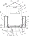
FIG. 1 is a schematic configuration diagram of a first state of a heat treatment apparatus having a rapid quenching function in example 1.
Fig. 2 is a structural view illustrating a second state of the heat treatment apparatus having a rapid quenching function.
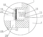
Fig. 3 is an enlarged view of a portion a in fig. 1.
Fig. 4 is a schematic structural diagram of a driving disk in a heat treatment apparatus having a rapid quenching function.
Fig. 5 is a schematic view showing the structure of a mounting bar in a heat treatment apparatus having a rapid quenching function.
In the figure: 1-main body, 2-cooling tank, 3-circulation cavity, 4-moving cylinder, 5-driving disk, 6-connecting rod, 7-driving shaft, 8-motor, 9-A gear, 10-B gear, 11-A bevel gear, 12-rotating shaft, 13-B bevel gear, 14-first one-way port, 15-second one-way port, 16-elastic piece, 17-sealing cover, 18-filter screen, 19-cleaning brush, 20-mounting rod, 21-bearing seat, 22-lifting cylinder, 23-blower, 24-condensing shell, 25-lug, 26-air outlet, 27-liquid collecting tank, 28-slag collecting tank and 29-closing plate.
Detailed Description
In the description of the present invention, it is to be understood that the terms "central," "longitudinal," "lateral," "upper," "lower," "front," "rear," "left," "right," "vertical," "horizontal," "top," "bottom," "inner," "outer," and the like are used in the orientation or positional relationship indicated in the drawings for convenience in describing the invention and for simplicity in description, and do not indicate or imply that the referenced device or element must have a particular orientation, be constructed and operated in a particular orientation, and thus, are not to be considered as limiting. Furthermore, the terms "first", "second", etc. are used for descriptive purposes only and are not to be construed as indicating or implying relative importance or implicitly indicating the number of technical features indicated. Thus, a feature defined as "first," "second," etc. may explicitly or implicitly include one or more of that feature. In the description of the present invention, "plurality" means two or more unless otherwise specified.
The technical solutions in the embodiments of the present invention will be clearly and completely described below with reference to the drawings in the embodiments of the present invention, and it is obvious that the described embodiments are only a part of the embodiments of the present invention, and not all of the embodiments. All other embodiments, which can be derived by a person skilled in the art from the embodiments given herein without making any creative effort, shall fall within the protection scope of the present invention.
Example 1
Referring to fig. 1 to 2, in embodiment 1 of the present invention, a heat treatment apparatus with a rapid quenching function includes a main body 1, a cooling tank 2 for cooling a part is disposed inside the main body 1, and two sides of the cooling tank 2 are respectively provided with a circulation cavity 3 with an intermittently changing volume;
wherein, the circulation cavity 3 at two sides is respectively provided with a first one-way port 14 for intermittently spraying cooling liquid and a second one-way port 15 for intermittently inputting cooling liquid, outlets of the first one-way ports 14 at two sides are both arranged on the circulation cavity 3, and the cooling liquid outlet directions of the first one-way ports 14 at two sides enter the cooling pool 2 from the circulation cavity 3; the arrangement is convenient for the cooling liquid in the circulating cavity 3 to enter the cooling pool 2, so that the cooling liquid in the cooling pool 2 is in a flowing state, and the cooling efficiency is improved;
two ends of the second one-way ports 15 on two sides are respectively communicated with the circulating cavity 3 and the interior of the cooling pool 2, and the flow direction of the second one-way ports 15 on two sides is from the cooling pool 2 to the interior of the circulating cavity 3; cooling is circulated between the cooling pool 2 and the circulation cavity 3 through the second one-way port 15 and the first one-way port 14, so that the cooling efficiency is improved, and the cooling is more uniform;
a filter screen 18 is installed at the inlet of the second one-way port 15, and a slag removing component for cleaning the outer surface of the filter screen 18 is arranged in the cooling pool 2 in a self-rotating manner. Set up the slagging-off part and prevent that filter screen 18 from blockking up, can produce the waste residue in the quenching process, can concentrate on filter screen 18 under the promotion of coolant liquid flow, handle it through the slagging-off part, and then guarantee the cleanliness of the inside coolant liquid of cooling bath 2.
The first one-way ports 14 on both sides are arranged in a staggered manner, so that the flowability of the cooling liquid is improved.
Example 2
Referring to fig. 1 to 5, the main difference between the present embodiment 2 and the embodiment 1 is that the slag removing component includes a rotating shaft 12 rotatably disposed inside the cooling tank 2, mounting rods 20 are fixedly mounted on two sides of the rotating shaft 12, a cleaning brush 19 is fixedly mounted on one end of the mounting rods 20 away from the rotating shaft 12, the cleaning brush 19 is attached to the filter screen 18, a slag collecting groove 28 for collecting waste slag is disposed under the filter screen 18, the slag collecting groove 28 is disposed at the bottom of the cooling tank 2, the rotating shaft 12 drives the cleaning brush 19 to rotate through the mounting rods 20, and the cleaning brush 19 cleans waste slag collected on the filter screen 18 during rotation, so that the waste slag enters the slag collecting groove 28 and the cleanliness of the cooling liquid is ensured.
The cleaning brush 19 is obliquely arranged, and the cleaning brush 19 is obliquely arranged, so that when the cleaning brush 19 rotates to clean the filter screen 18, waste residues move downwards to enter the residue accumulation groove 28.
The bottom of the slag accumulation groove 28 is provided with a closing plate 29 which can be opened and closed, when the slag accumulation groove needs to be cleaned, the closing plate 29 is opened, waste slag is cleaned, and the slag collection device is convenient to use. One end of the closing plate 29 is hinged to the bottom of the main body 1, and the other end of the closing plate is installed at the bottom of the main body 1 through a bolt, so that an outlet at the bottom of the slag accumulating groove 28 is closed.
And movable cylinders 4 capable of ascending and descending are arranged in the circulating cavities 3 on the two sides. The moving cylinder 4 is arranged to lift back and forth in the circulating cavity 3, so that the internal volume of the circulating cavity 3 is changed. The bottom of the moving cylinder 4 penetrates through the bottom of the circulating cavity 3.
The main body 1 is also provided with a reciprocating component for driving the moving cylinder 4 to move up and down.
Reciprocating unit is including rotating drive shaft 7 of installing in main part 1 bottom, drive shaft 7 both sides are fixed mounting respectively has driving-disc 5, rotate on the driving-disc 5 and install connecting rod 6, connecting rod 6 is kept away from driving-disc 5 one end and is rotated and install in the bottom of removing jar 4, connecting rod 6 is installed in driving-disc 5 non-central point and puts, and driving-disc 5 rotates and drives through connecting rod 6 and remove jar 4 and reciprocate, and then intermittent change circulation 3 internal volumes in chamber, and then make the coolant liquid circulate between cooling tank 2 and circulation chamber 3.
The driving shaft 7 is fixedly sleeved with a gear B10, the gear B10 is meshed with a gear A9 at the input end of a motor 8, and the motor 8 is fixedly installed on the main body 1. The motor 8 is electrified to rotate, and then the driving shaft 7 is driven to rotate through the rotation of the gear A9 and the gear B10, so that power is provided for the rotation of the driving shaft 7.
And a transmission assembly is further arranged between the driving shaft 7 and the rotating shaft 12 and provides power for the rotation of the rotating shaft 12.
The transmission component comprises a B bevel gear 13 fixedly sleeved on the driving shaft 7 and an A bevel gear 11 meshed with the B bevel gear 13, the A bevel gear 11 is fixedly sleeved on a rotating shaft 12, the rotating shaft 12 penetrates through the bottom of the main body 1, and the A bevel gear 11 is arranged below the rotating shaft 12. The arrangement provides power for rotation of the rotatable shaft 12.
The opening of the second one-way port 15 is provided with a sealing cover 17, one side of the sealing cover 17 is fixedly provided with an elastic part 16, one end, far away from the sealing cover 17, of the elastic part 16 is fixedly arranged inside the second one-way port 15, and the opening of the second one-way port 15 is sealed by the elastic part 16 and the sealing cover 17, so that the cooling pool 2 and the circulation cavity 3 are prevented from being communicated.
The main part 1 is further provided with a bearing seat 21, two sides of the bearing seat 21 are respectively and fixedly installed at the output end of the lifting cylinder 22, the lifting cylinder 22 is fixedly installed on the main part 1, the part needing quenching is placed on the bearing seat 21 conveniently through the arrangement, and then the part is automatically added into the cooling pool 2 to be cooled, so that automatic feeding is realized.
As much steam is generated in the quenching process, if the steam is not collected, the temperature of the whole workshop is too high and damp, so that a condensing shell 24 needs to be arranged on the main body 1, and the condensing shell 24 is arranged right above the cooling pool 2; the 24 import departments of condensing shell are provided with fan 23, set up inside fan 23 inhales steam to condensing shell 24, 24 both sides of condensing shell slope sets up, and 24 both sides of condensing shell set up and be provided with long-pending cistern 27 and be used for collecting the condensate, long-pending cistern 27 passes through pipeline and cooling tank 2 intercommunication for the condensate can recycle.
A plurality of lugs 25 are fixedly mounted on the side wall of the condensation shell 24, the lugs 25 are arranged to improve the condensation area, an air outlet 26 is further formed in the side wall of the condensation shell 24, and the air outlet 26 is arranged to facilitate air discharge.
The working principle of the invention is as follows: placing parts to be quenched on a bearing seat 21, extending a lifting cylinder 22 to enable the parts on the bearing seat 21 to enter a cooling tank 2, simultaneously rotating a motor 8, driving a driving disc 5 to rotate through an A gear 9, a B gear 10 and a driving shaft 7, driving the driving disc 5 to drive a moving cylinder 4 to move up and down through a connecting rod 6, changing the internal volume of a circulating cavity 3, when the moving cylinder 4 moves downwards, increasing the internal volume of the circulating cavity 3, changing the pressure, closing a first one-way port 14, opening a second one-way port 15, enabling cooling liquid in the cooling tank 2 to enter the circulating cavity 3 through the second one-way port 15, and filling the inside of the circulating cavity 3 with the cooling liquid; when the movable cylinder 4 moves upwards, the volume inside the circulation cavity 3 is reduced, the pressure is increased, the second one-way port 15 is closed, the first one-way port 14 is opened to discharge the cooling liquid in the circulation cavity 3 into the cooling pool 2, so that the cooling liquid inside the cooling pool 2 is in a flowing state, and the cooling effect is improved; meanwhile, the driving shaft 7 drives the rotating shaft 12 to rotate through the transmission assembly, the rotating shaft 12 drives the cleaning brush 19 on the mounting rod 20 to rotate to clean the outer surface of the filter screen 18 on the second one-way port 15, and cleaned waste residues enter the residue accumulating groove 28, so that the cooling liquid circulation pipeline is prevented from being blocked, and the waste residues in the cooling pool 2 are cleaned; the coolant can be easily recovered by providing the projection 25, the fan 23, the liquid accumulating tank 27, and the like.
It will be evident to those skilled in the art that the invention is not limited to the details of the foregoing illustrative embodiments, and that the present invention may be embodied in other specific forms without departing from the spirit or essential attributes thereof. The present embodiments are therefore to be considered in all respects as illustrative and not restrictive, the scope of the invention being indicated by the appended claims rather than by the foregoing description, and all changes which come within the meaning and range of equivalency of the claims are therefore intended to be embraced therein. Any reference sign in a claim should not be construed as limiting the claim concerned.
Furthermore, it should be understood that although the present description refers to embodiments, not every embodiment may contain only a single embodiment, and such description is for clarity only, and those skilled in the art should integrate the description, and the embodiments may be combined as appropriate to form other embodiments understood by those skilled in the art.
Claims (1)
1. A heat treatment device with a rapid quenching function comprises a main body (1), wherein a cooling pool (2) for cooling a part is arranged in the main body (1), and two sides of the cooling pool (2) are respectively provided with a circulating cavity (3) with intermittently changed volume; the cooling device is characterized in that a first one-way port (14) for intermittently spraying cooling liquid and a second one-way port (15) for intermittently inputting the cooling liquid are respectively arranged on the circulating cavities (3) on the two sides, outlets of the first one-way ports (14) on the two sides are respectively arranged on the circulating cavity (3), and the cooling liquid outlet directions of the first one-way ports (14) on the two sides enter the cooling pool (2) from the circulating cavity (3); two ends of the second one-way ports (15) on two sides are respectively communicated with the interior of the circulating cavity (3) and the interior of the cooling pool (2), and the flow direction of the second one-way ports (15) on two sides is from the cooling pool (2) to the interior of the circulating cavity (3); a filter screen (18) is arranged at the inlet of the second one-way port (15), and a slag removing component for cleaning the outer surface of the filter screen (18) is arranged in the cooling pool (2) in a self-rotating manner; both sides first one-way mouth (14) setting of staggering, the slagging-off part is including rotating axis of rotation (12) that sets up in cooling tank (2) inside, axis of rotation (12) both sides fixed mounting has installation pole (20), rotation axis (12) one end fixed mounting is kept away from in installation pole (20) has cleaning brush (19), cleaning brush (19) are pasted and are put on filter screen (18), be provided with long-pending sediment groove (28) that are used for collecting the waste residue under filter screen (18), long-sediment groove (28) set up in cooling tank (2) bottom, cleaning brush (19) slope sets up, long-sediment groove (28) bottom is provided with closing plate (29) that can open and shut, closing plate (29) one end articulates in main part (1) bottom, and the other end passes through the bolt and installs in main part (1) bottom, both sides be provided with removal jar (4) that can go up and down in circulation chamber (3), the device is characterized in that a reciprocating component for driving the moving cylinder (4) to move up and down is further arranged on the main body (1), the reciprocating component comprises a driving shaft (7) which is rotatably arranged at the bottom of the main body (1), driving discs (5) are respectively and fixedly arranged on two sides of the driving shaft (7), a connecting rod (6) is rotatably arranged on the driving discs (5), one end, far away from the driving discs (5), of the connecting rod (6) is rotatably arranged at the bottom of the moving cylinder (4), the connecting rod (6) is arranged at the non-central position of the driving discs (5), a gear B (10) is fixedly sleeved on the driving shaft (7), the gear B (10) is meshed with a gear A (9) at the input end of the motor (8), the motor (8) is fixedly arranged on the main body (1), a transmission assembly is further arranged between the driving shaft (7) and the rotating shaft (12), and a bearing seat (21) is further arranged on the main body (1), bear seat (21) both sides respectively fixed mounting at the output of lift cylinder (22), lift cylinder (22) fixed mounting is on main part (1).
Priority Applications (1)
| Application Number | Priority Date | Filing Date | Title |
|---|---|---|---|
| CN202010202770.XA CN111349764B (en) | 2020-03-20 | 2020-03-20 | Heat treatment equipment with rapid quenching function |
Applications Claiming Priority (1)
| Application Number | Priority Date | Filing Date | Title |
|---|---|---|---|
| CN202010202770.XA CN111349764B (en) | 2020-03-20 | 2020-03-20 | Heat treatment equipment with rapid quenching function |
Publications (2)
| Publication Number | Publication Date |
|---|---|
| CN111349764A CN111349764A (en) | 2020-06-30 |
| CN111349764B true CN111349764B (en) | 2022-09-23 |
Family
ID=71194613
Family Applications (1)
| Application Number | Title | Priority Date | Filing Date |
|---|---|---|---|
| CN202010202770.XA Active CN111349764B (en) | 2020-03-20 | 2020-03-20 | Heat treatment equipment with rapid quenching function |
Country Status (1)
| Country | Link |
|---|---|
| CN (1) | CN111349764B (en) |
Families Citing this family (6)
| Publication number | Priority date | Publication date | Assignee | Title |
|---|---|---|---|---|
| CN112195324B (en) * | 2020-10-16 | 2022-10-11 | 温州宇岚科技有限公司 | Automatic quenching device for motorcycle aluminum alloy hub after demolding |
| CN113755676A (en) * | 2021-10-14 | 2021-12-07 | 常熟市常力紧固件有限公司 | A kind of heat treatment device and method for high strength automobile bolt |
| CN114150121B (en) * | 2021-12-17 | 2023-12-19 | 大连德迈仕精密科技股份有限公司 | Quenching equipment for automobile engine crankshaft production and processing method |
| CN114704992B (en) * | 2022-02-16 | 2023-10-20 | 深圳市科姆森制冷设备有限公司 | Industrial refrigerating fluid circulation intelligent environment-friendly device |
| CN116121524A (en) * | 2023-03-08 | 2023-05-16 | 柳州市工大机械有限公司 | Heat treatment equipment with rapid quenching function |
| CN118813916B (en) * | 2024-09-12 | 2025-01-28 | 廊坊光华热处理表面工程有限公司 | Metal parts heat treatment equipment |
Citations (2)
| Publication number | Priority date | Publication date | Assignee | Title |
|---|---|---|---|---|
| CN206345876U (en) * | 2017-01-19 | 2017-07-21 | 范兴旺 | A kind of metal material annealing device |
| CN209873027U (en) * | 2019-05-22 | 2019-12-31 | 马鞍山市恒泰重工机械有限公司 | Feeding and cooling device of high-frequency quenching machine |
Family Cites Families (1)
| Publication number | Priority date | Publication date | Assignee | Title |
|---|---|---|---|---|
| JPS59193213A (en) * | 1983-04-18 | 1984-11-01 | Chugoku Shiyouene Kiki Hanbai Kk | Salt removal of salt bath heat-treated steel |
-
2020
- 2020-03-20 CN CN202010202770.XA patent/CN111349764B/en active Active
Patent Citations (2)
| Publication number | Priority date | Publication date | Assignee | Title |
|---|---|---|---|---|
| CN206345876U (en) * | 2017-01-19 | 2017-07-21 | 范兴旺 | A kind of metal material annealing device |
| CN209873027U (en) * | 2019-05-22 | 2019-12-31 | 马鞍山市恒泰重工机械有限公司 | Feeding and cooling device of high-frequency quenching machine |
Also Published As
| Publication number | Publication date |
|---|---|
| CN111349764A (en) | 2020-06-30 |
Similar Documents
| Publication | Publication Date | Title |
|---|---|---|
| CN111349764A (en) | Heat treatment equipment with rapid quenching function | |
| CN117824389B (en) | Heat exchanger convenient to clean | |
| CN111987604B (en) | Low-voltage power electric cabinet | |
| CN213885239U (en) | A filter equipment is collected to sewage for being directed at cooling tower washs | |
| CN116196692A (en) | Wire drawing machine cooling water filters cooling arrangement | |
| CN219829633U (en) | Wind-powered electricity generation gear box radiator dust collector | |
| CN212398356U (en) | Cutting equipment with cooling protection function | |
| CN218871413U (en) | Sewage treatment equipment with multi-stage filtration | |
| CN216523359U (en) | Energy-saving scale prevention closed cooling circulation device for thermal power plant | |
| CN115405447A (en) | Air inlet filter equipment for automobile engine | |
| CN212033620U (en) | Metal-enclosed looped network switch equipment with good heat dissipation effect | |
| CN222196061U (en) | Water quality purifying device for ground source heat pump system | |
| CN219463716U (en) | Combined centrifugal oil purifier | |
| CN217613184U (en) | Reclaimed water reuse sewage treatment equipment | |
| CN219032262U (en) | Quenching oil cooling circulation device of wear-resistant cast ball quenching furnace | |
| CN116202317A (en) | Support driving device of rotary kiln for barium sulfate production | |
| CN112276430B (en) | Electric welding with good thermal diffusivity | |
| CN217449204U (en) | Sewage source heat pump reclaimed water reutilization concentrates energy supply system | |
| CN219218082U (en) | Quenching tank for steel manufacturing | |
| CN222710409U (en) | Large-scale sintering machine of sintering plant convenient to clean | |
| CN211417224U (en) | Cooling liquid circulating device | |
| CN218553468U (en) | Filter equipment that air source heat pump set used | |
| CN211695517U (en) | Fan defrosting water cyclic utilization system | |
| CN220214158U (en) | Sewage treatment equipment for environmental treatment | |
| CN222187872U (en) | A condensate recovery device for fine steel preparation |
Legal Events
| Date | Code | Title | Description |
|---|---|---|---|
| PB01 | Publication | ||
| PB01 | Publication | ||
| SE01 | Entry into force of request for substantive examination | ||
| SE01 | Entry into force of request for substantive examination | ||
| TA01 | Transfer of patent application right | ||
| TA01 | Transfer of patent application right |
Effective date of registration: 20220822 Address after: Magang Village, Magang Township, Shenbei New District, Shenyang City, Liaoning Province 110124 Applicant after: LIAONING YISHENG TECHNOLOGY GROUP CO.,LTD. Address before: 318050 no.821 Xin'an South Street, Luqiao street, Luqiao District, Taizhou City, Zhejiang Province Applicant before: Chen Zengfa |
|
| GR01 | Patent grant | ||
| GR01 | Patent grant |