CN111347267A - Pipe part drilling clamp - Google Patents
Pipe part drilling clamp Download PDFInfo
- Publication number
- CN111347267A CN111347267A CN201811570483.3A CN201811570483A CN111347267A CN 111347267 A CN111347267 A CN 111347267A CN 201811570483 A CN201811570483 A CN 201811570483A CN 111347267 A CN111347267 A CN 111347267A
- Authority
- CN
- China
- Prior art keywords
- chuck
- pipe parts
- pipe part
- clamping piece
- base
- Prior art date
- Legal status (The legal status is an assumption and is not a legal conclusion. Google has not performed a legal analysis and makes no representation as to the accuracy of the status listed.)
- Pending
Links
Images


Classifications
-
- B—PERFORMING OPERATIONS; TRANSPORTING
- B23—MACHINE TOOLS; METAL-WORKING NOT OTHERWISE PROVIDED FOR
- B23Q—DETAILS, COMPONENTS, OR ACCESSORIES FOR MACHINE TOOLS, e.g. ARRANGEMENTS FOR COPYING OR CONTROLLING; MACHINE TOOLS IN GENERAL CHARACTERISED BY THE CONSTRUCTION OF PARTICULAR DETAILS OR COMPONENTS; COMBINATIONS OR ASSOCIATIONS OF METAL-WORKING MACHINES, NOT DIRECTED TO A PARTICULAR RESULT
- B23Q3/00—Devices holding, supporting, or positioning work or tools, of a kind normally removable from the machine
- B23Q3/02—Devices holding, supporting, or positioning work or tools, of a kind normally removable from the machine for mounting on a work-table, tool-slide, or analogous part
- B23Q3/06—Work-clamping means
-
- B—PERFORMING OPERATIONS; TRANSPORTING
- B23—MACHINE TOOLS; METAL-WORKING NOT OTHERWISE PROVIDED FOR
- B23Q—DETAILS, COMPONENTS, OR ACCESSORIES FOR MACHINE TOOLS, e.g. ARRANGEMENTS FOR COPYING OR CONTROLLING; MACHINE TOOLS IN GENERAL CHARACTERISED BY THE CONSTRUCTION OF PARTICULAR DETAILS OR COMPONENTS; COMBINATIONS OR ASSOCIATIONS OF METAL-WORKING MACHINES, NOT DIRECTED TO A PARTICULAR RESULT
- B23Q1/00—Members which are comprised in the general build-up of a form of machine, particularly relatively large fixed members
- B23Q1/25—Movable or adjustable work or tool supports
-
- B—PERFORMING OPERATIONS; TRANSPORTING
- B23—MACHINE TOOLS; METAL-WORKING NOT OTHERWISE PROVIDED FOR
- B23Q—DETAILS, COMPONENTS, OR ACCESSORIES FOR MACHINE TOOLS, e.g. ARRANGEMENTS FOR COPYING OR CONTROLLING; MACHINE TOOLS IN GENERAL CHARACTERISED BY THE CONSTRUCTION OF PARTICULAR DETAILS OR COMPONENTS; COMBINATIONS OR ASSOCIATIONS OF METAL-WORKING MACHINES, NOT DIRECTED TO A PARTICULAR RESULT
- B23Q17/00—Arrangements for observing, indicating or measuring on machine tools
- B23Q17/22—Arrangements for observing, indicating or measuring on machine tools for indicating or measuring existing or desired position of tool or work
- B23Q17/2291—Arrangements for observing, indicating or measuring on machine tools for indicating or measuring existing or desired position of tool or work for adjusting the workpiece relative to the holder thereof
-
- B—PERFORMING OPERATIONS; TRANSPORTING
- B23—MACHINE TOOLS; METAL-WORKING NOT OTHERWISE PROVIDED FOR
- B23Q—DETAILS, COMPONENTS, OR ACCESSORIES FOR MACHINE TOOLS, e.g. ARRANGEMENTS FOR COPYING OR CONTROLLING; MACHINE TOOLS IN GENERAL CHARACTERISED BY THE CONSTRUCTION OF PARTICULAR DETAILS OR COMPONENTS; COMBINATIONS OR ASSOCIATIONS OF METAL-WORKING MACHINES, NOT DIRECTED TO A PARTICULAR RESULT
- B23Q3/00—Devices holding, supporting, or positioning work or tools, of a kind normally removable from the machine
- B23Q3/02—Devices holding, supporting, or positioning work or tools, of a kind normally removable from the machine for mounting on a work-table, tool-slide, or analogous part
- B23Q3/06—Work-clamping means
- B23Q3/062—Work-clamping means adapted for holding workpieces having a special form or being made from a special material
- B23Q3/064—Work-clamping means adapted for holding workpieces having a special form or being made from a special material for holding elongated workpieces, e.g. pipes, bars or profiles
Landscapes
- Engineering & Computer Science (AREA)
- Mechanical Engineering (AREA)
- Drilling And Boring (AREA)
Abstract
本发明涉及一种管类零件钻孔夹具。该管类零件钻孔夹具包括用于固定在适配机床上的底座,底座上可转动的装配有旋转架,底座和/或旋转架上设有用于测量旋转架旋转角度的旋转刻度,旋转架上设有用于配合夹持固定待加工管类零件的夹持结构,夹持结构包括至少一个活动夹持件,还包括用于驱动待加工管类零件回转的卡盘,卡盘与所述活动夹持件沿卡盘轴向间隔布置,旋转架和/或卡盘上设有用于测量卡盘驱动待加工管类零件回转角度的回转刻度。该管类零件钻孔夹具操作方便、结构简单、加工精度高,能够实现管类零件在圆周方向和轴向方向的不同角度孔的加工,非常实用。
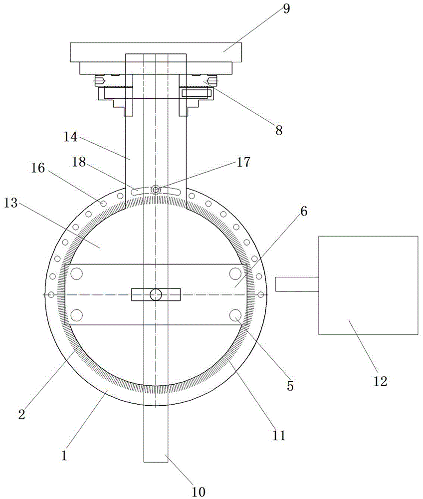
The invention relates to a drilling fixture for pipe parts. The pipe parts drilling fixture includes a base for fixing on a suitable machine tool, a rotating frame is rotatably mounted on the base, and a rotating scale for measuring the rotation angle of the rotating frame is provided on the base and/or the rotating frame. There is a clamping structure for cooperating to clamp and fix the pipe parts to be processed. The clamping structure includes at least one movable clamping piece, and also includes a chuck for driving the pipe parts to be processed to rotate. The chuck is connected with the movable clamp. The clamping pieces are arranged at intervals along the axial direction of the chuck, and the rotary frame and/or the chuck are provided with a rotation scale for measuring the rotation angle of the pipe parts to be processed driven by the chuck. The pipe parts drilling fixture has the advantages of convenient operation, simple structure and high machining accuracy, and can realize the machining of holes of different angles in the circumferential direction and the axial direction of the pipe parts, and is very practical.
Description
技术领域technical field
本发明涉及一种管类零件钻孔夹具。The invention relates to a drilling fixture for pipe parts.
背景技术Background technique
目前,在机械行业中,经常需要对管类零件上进行不同角度的钻孔,这些孔在加工之前往往需要精确的位置关系,包括轴向直线位置关系和径向圆周上角度位置关系。现有的方法对管类零件上不同角度孔的加工主要采用划线配合通用钻孔夹具或者使用数控加工的方式,但是这两种方法在加工精度、生产成本、劳动强度等方面都有各自的不足。At present, in the machinery industry, it is often necessary to drill different angles on pipe parts, and these holes often require precise positional relationships before machining, including the axial linear positional relationship and the angular positional relationship on the radial circumference. Existing methods mainly use scribing and general drilling fixtures or CNC machining to process holes with different angles on pipe parts, but these two methods have their own differences in machining accuracy, production cost, and labor intensity. insufficient.
针对上述两种方法的不足,授权公告号为CN103658762B的中国发明专利公开了一种直线圆柱类零件径向精确钻孔夹具。该钻孔夹具包括底座,底座上设置分度头,分度头上安装有能够固定圆柱类零件其中一端的三爪卡盘;底座上还设置有轨道,轨道上设置有滑块,滑块两侧安装有螺柱,螺柱顶端固定有压板;底座上还活动设置有可在底座上滑动的钻孔支架。上述钻孔夹具通过分度头可以精确调整圆柱类零件圆周方向上的角度,钻孔支架可以精确定位圆柱类零件的轴向位置,但是,该钻孔夹具并不能对圆柱类零件的轴向不同角度的孔(比如斜孔)进行加工,对于一些特殊的需要在轴向加工不同角度孔的圆柱类零件来讲并不适用。In view of the shortcomings of the above two methods, the Chinese invention patent with the authorization announcement number CN103658762B discloses a radially precise drilling fixture for linear cylindrical parts. The drilling jig includes a base, an indexing head is arranged on the base, and a three-jaw chuck capable of fixing one end of a cylindrical part is installed on the indexing head; a track is also arranged on the base, and a slider is arranged on the track. A stud is installed on the side, and a pressure plate is fixed on the top of the stud; a drilling bracket that can slide on the base is also movably arranged on the base. The above-mentioned drilling fixture can precisely adjust the angle in the circumferential direction of cylindrical parts through the indexing head, and the drilling bracket can precisely locate the axial position of cylindrical parts. However, the drilling fixture cannot adjust the axial direction of cylindrical parts. Angled holes (such as inclined holes) are not suitable for some special cylindrical parts that need to machine holes with different angles in the axial direction.
发明内容SUMMARY OF THE INVENTION
本发明的目的在于提供一种管类零件钻孔夹具,以解决现有技术中的钻孔夹具不能同时实现对管类零件圆周方向和轴向方向不同角度的孔的加工的技术问题。The purpose of the present invention is to provide a drilling fixture for pipe parts, so as to solve the technical problem that the drilling fixture in the prior art cannot simultaneously process holes with different angles in the circumferential direction and the axial direction of the pipe parts.
为实现上述目的,本发明提供的管类零件钻孔夹具的技术方案是:管类零件钻孔夹具包括用于固定在适配机床上的底座,底座上可转动的装配有旋转架,底座和/或旋转架上设有用于测量旋转架旋转角度的旋转刻度,旋转架上设有用于配合夹持固定待加工管类零件的夹持结构,夹持结构包括至少一个活动夹持件,还包括用于驱动待加工管类零件回转的卡盘,卡盘与所述活动夹持件沿卡盘轴向间隔布置,旋转架和/或卡盘上设有用于测量待加工管类零件回转角度的回转刻度。In order to achieve the above purpose, the technical scheme of the pipe parts drilling fixture provided by the present invention is as follows: the pipe parts drilling fixture includes a base for fixing on a matching machine tool, and a rotating frame is rotatably assembled on the base, and the base and /or the rotating frame is provided with a rotating scale for measuring the rotation angle of the rotating frame, and the rotating frame is provided with a clamping structure for cooperating with clamping and fixing the pipe parts to be processed, the clamping structure includes at least one movable clamping piece, and also includes A chuck for driving the rotation of the pipe parts to be processed, the chuck and the movable clamping part are arranged at intervals along the axial direction of the chuck, and the rotating frame and/or the chuck are provided with a rotating frame for measuring the rotation angle of the pipe parts to be processed. Rotation scale.
本发明的有益效果是:该管类零件钻孔夹具的底座上转动装配有旋转架,并且旋转架和/或底座上设有测量旋转架旋转角度的旋转刻度,即当待加工管类零件在固定夹紧后,通过旋转旋转架就能实现整个待加工管类零件在轴向上的旋转,需要加工不同角度的孔时,通过调整旋转角度即可实现;同时,旋转架上设有用于驱动待加工管类零件沿其轴向旋转的卡盘,且旋转架和/或卡盘上具有测量待加工管类零件回转角度的回转刻度,即能实现待加工管类零件在其圆周向不同角度的孔的加工。整套管类零件钻孔夹具通过旋转架以及其上设置的卡盘的作用,实现待加工管类零件轴向和周向的旋转,从而既能对待加工管类零件轴向上不同角度孔的加工,又能对待加工管类零件圆周上不同角度孔的加工,并且整套管类钻孔夹具操作方便、结构简单、加工精度高,非常实用。The beneficial effects of the present invention are as follows: the base of the pipe parts drilling fixture is rotatably assembled with a rotating frame, and the rotating frame and/or the base is provided with a rotating scale for measuring the rotation angle of the rotating frame, that is, when the pipe parts to be processed are in After being fixed and clamped, the entire tube parts to be processed can be rotated in the axial direction by rotating the rotary frame. When holes with different angles need to be processed, it can be achieved by adjusting the rotation angle; A chuck that rotates the pipe parts to be processed along its axial direction, and the rotary frame and/or the chuck has a rotary scale for measuring the rotation angle of the pipe parts to be processed, that is, it can realize the different angles of the pipe parts to be processed in the circumferential direction. hole machining. The whole casing parts drilling fixture realizes the axial and circumferential rotation of the pipe parts to be processed through the action of the rotating frame and the chuck set on it, so that it can not only process the holes of different angles in the axial direction of the pipe parts to be processed It can also handle the processing of holes with different angles on the circumference of the processing pipe parts, and the whole casing drilling fixture is easy to operate, simple in structure, and high in processing accuracy, which is very practical.
进一步地,所述夹持结构包括固设在所述旋转架上的固定夹持件,固定夹持件与所述活动夹持件配合以对待加工管类零件进行固定。Further, the clamping structure includes a fixed clamping piece fixed on the rotating frame, and the fixed clamping piece cooperates with the movable clamping piece to fix the pipe parts to be processed.
有益效果是:夹持机构包括活动夹持件和固定夹持件,有利于待加工管类零件的夹紧,同时也便于调整待加工管类零件的装夹角度。The beneficial effect is that the clamping mechanism includes a movable clamping piece and a fixed clamping piece, which is beneficial to the clamping of the pipe parts to be processed, and also facilitates the adjustment of the clamping angle of the pipe parts to be processed.
进一步地,所述活动夹持件上连接有用于驱动活动夹持件朝向或远离固定夹持件运动的丝杆。Further, the movable clamp is connected with a screw rod for driving the movable clamp to move toward or away from the fixed clamp.
有益效果是:活动夹持件采用丝杆驱动,人工操作时更加方便、省力。The beneficial effects are: the movable clamping piece is driven by a screw rod, which is more convenient and labor-saving during manual operation.
进一步地,所述活动夹持件和固定夹持件均为V型块,两块V型块通过上下对夹的方式对待加工管类零件进行夹持固定。Further, the movable clamping piece and the fixed clamping piece are both V-shaped blocks, and the two V-shaped blocks are clamped and fixed to the pipe parts to be processed by means of upper and lower clamping.
有益效果是:V型块具有两个定位面,便于对管类零件进行装夹,不需要专门的夹具。The beneficial effects are: the V-shaped block has two positioning surfaces, which is convenient for clamping the pipe parts, and does not need a special fixture.
进一步地,管类零件钻孔夹具还包括设置在旋转架上的门架结构,门架结构包括与旋转架平行设置的支撑板和立设在支撑板与旋转架之间的支撑杆,所述丝杆贯穿支撑板与所述活动夹持件连接。Further, the pipe parts drilling fixture also includes a gantry structure arranged on the revolving frame, and the gantry structure includes a support plate arranged in parallel with the revolving frame and a support rod erected between the support plate and the revolving frame, the The screw rod penetrates through the support plate and is connected with the movable clamping piece.
有益效果是:丝杆与活动夹持块连接并且贯穿支撑板有利于活动夹持块的放置,无需在使用时人工再去取活动夹持块,支撑杆用于支撑支撑板使其更加稳固。The beneficial effect is that the screw rod is connected with the movable clamping block and penetrates the support plate, which is conducive to the placement of the movable clamping block, and there is no need to manually remove the movable clamping block during use, and the support rod is used to support the support plate to make it more stable.
进一步地,所述旋转架包括用于固定所述卡盘的分度头,分度头上设有所述回转刻度。Further, the rotating frame includes an indexing head for fixing the chuck, and the rotating scale is provided on the indexing head.
有益效果是:卡盘固定在分度头上且分度头上具有回转刻度,能够测量卡盘驱动待加工管类零件沿其周向旋转的角度,以更加精确的在待加工管类零件的周向加工所需的角度孔。The beneficial effects are: the chuck is fixed on the indexing head and the indexing head has a rotary scale, which can measure the angle at which the chuck drives the pipe parts to be processed to rotate along its circumferential direction, so as to more accurately determine the position of the pipe parts to be processed. Angle holes required for circumferential machining.
进一步地,所述旋转架的转动中心轴线沿竖向延伸,卡盘的回转中心轴线沿水平方向延伸。Further, the rotation center axis of the rotating frame extends vertically, and the rotation center axis of the chuck extends horizontally.
有益效果是:能够实现水平方向夹紧的待加工管类零件的周向和轴向不同角度孔的加工。The beneficial effect is that the processing of holes with different angles in the circumferential direction and the axial direction of the pipe parts to be processed which are clamped in the horizontal direction can be realized.
进一步地,所述底座于所述旋转刻度的外侧沿圆周方向设有间隔布置的定位孔,旋转架上设有与之对应的弧形长孔,旋转架通过紧固螺钉同时穿入弧形长孔和定位孔中实现在底座上的定位。Further, the base is provided with positioning holes arranged at intervals along the circumferential direction on the outer side of the rotating scale, the rotating frame is provided with corresponding arc-shaped long holes, and the rotating frame is simultaneously penetrated into the arc-shaped long holes by tightening screws. The positioning on the base is realized in the hole and the positioning hole.
有益效果是:底座于旋转刻度的外侧沿圆周方向设有间隔布置的定位孔,使得待加工管类零件在加工轴向不同角度孔时能实现在底座上的有效定位。The beneficial effect is that the base is provided with positioning holes arranged at intervals along the circumferential direction on the outer side of the rotating scale, so that the pipe parts to be processed can be effectively positioned on the base when processing holes of different axial angles.
附图说明Description of drawings
图1为本发明提供的管类零件钻孔夹具的主视图;Fig. 1 is the front view of the pipe parts drilling fixture provided by the present invention;
图2为本发明提供的管类零件钻孔夹具的俯视图;Fig. 2 is the top view of the pipe parts drilling fixture provided by the present invention;
图3为本发明提供的管类零件钻孔夹具的侧视图;Fig. 3 is the side view of the pipe parts drilling fixture provided by the present invention;
图4为本发明提供的管类零件钻孔夹具与机床配合使用的示意图。FIG. 4 is a schematic diagram of the use of the pipe parts drilling fixture provided by the present invention in cooperation with a machine tool.
图中:1-底座,2-旋转架,3-下V型块,4-上V型块,5-支撑杆,6-支撑板,7-丝杆,8-三爪卡盘,9-分度头,10-待加工管类零件,11-旋转刻度,12-机床,13-旋转座,14-延伸段,15-转轴,16-定位孔,17-紧固螺钉,18-弧形长孔。In the picture: 1-base, 2-rotating frame, 3-lower V-block, 4-upper V-block, 5-support rod, 6-support plate, 7-screw rod, 8-three-jaw chuck, 9- Indexing head, 10-pipe parts to be processed, 11-rotating scale, 12-machine tool, 13-rotating seat, 14-extension section, 15-rotating shaft, 16-positioning hole, 17-fastening screw, 18-arc Long hole.
具体实施方式Detailed ways
下面结合附图对本发明的具体实施方式作进一步说明,但并不以此为限。The specific embodiments of the present invention will be further described below in conjunction with the accompanying drawings, but not limited thereto.
本发明提供的管类零件钻孔夹具的具体实施例,如图1、图2、图3和图4所示,该管类零件钻孔夹具包括固定在适配的机床12上的底座1,底座1上设有旋转架2,旋转架2通过其自身转轴15转动装配在底座1上。底座1上设有用于测量旋转架2旋转角度的旋转刻度11,底座1于旋转刻度11的圆周外侧设有半圈间隔布置的定位孔16。旋转架2包括旋转座13和与旋转座13为一体的凸出旋转座13外的延伸段14,延伸段14上对应定位孔16设有弧形长孔18,弧形长孔18和对应的定位孔16中同时穿入紧固螺钉17将整个旋转架2定位在底座1上;旋转架2上立设有用于配合夹持固定待加工管类零件10的夹持结构。As shown in Figure 1, Figure 2, Figure 3 and Figure 4, the specific embodiment of the pipe parts drilling fixture provided by the present invention includes a
夹持结构包括通过螺钉紧固装配在旋转座13上的固定夹持件和与固定夹持件配合使用的活动夹持件,如图1所示,本实施例中,固定夹持件为下V型块3,活动夹持件为上V型块4,两个夹持件通过上下对夹的方式将待加工管类零件10进行夹紧固定。由于V型块具有两个定位面,在对管类零件装夹时更加方便,不需要专用的夹具。旋转座13上还设有门架结构,门架结构包括支撑板6和立设在支撑板6与旋转座13之间的四根支撑杆5,上V型块4设置在支撑板6与旋转座13之间,并且上V型块4上固定连接有丝杆7,丝杆7贯穿支撑板6并与上V型块4连接,通过旋拧丝杆7从而驱动上V型块4在支撑板6与旋转座13之间朝向或远离下V型块3运动。The clamping structure includes a fixed clamping piece fastened and assembled on the rotating
如图2所示,夹持结构还包括固定在旋转架2的延伸段14上的分度头9,分度头9上转动装配有可用于驱动待加工管类零件10沿其周向旋转的三爪卡盘8,三爪卡盘8与上述的上、下V型块之间在三爪卡盘8的轴向上具有一定的间隔。分度头9上设有用于测量待加工管类零件10回转角度的回转刻度。As shown in FIG. 2 , the clamping structure further includes an indexing
本实施例中,旋转架2的转动中心轴线沿竖向延伸,卡盘的回转中心轴线沿水平方向延伸。In this embodiment, the rotation center axis of the
如图4所示,该管类零件钻孔夹具在装夹时,将待加工管类零件10的一端通过三爪卡盘8夹紧固定,另一端穿过下V型块3上的V型槽与下V型块3上的两个定位面接触,旋转丝杆7使得上V型块4向下移动与下V型块3共同压紧待加工管类零件10,此时,待加工管类零件10装夹完成。As shown in FIG. 4 , when the pipe parts drilling fixture is clamped, one end of the
当待加工管类零件10需要在圆周不同的方向进行孔加工或铣加工时,需要旋转丝杆7松开上V型块4,转动三爪卡盘8,实现待加工管类零件10的周向旋转,当待加工管类零件10旋转至周向所需加工的角度与分度头9上的回转刻度对应时,即旋转到位,此时旋转丝杆7使上V型块4向下压紧待加工管类零件10,压紧后即可通过机床12即可进行加工。When the
当待加工管类零件10在轴向上需要加工斜孔时,松开紧固螺钉17,然后转动旋转架2实现整个待加工管类零件10在轴向上的旋转,当待加工管类零件10在其轴向上旋转至所需加工的角度与底座1上的旋转刻度11对应时,即旋转到位,此时将紧固螺钉17穿入弧形长孔18和与其对应的定位孔16中,旋拧紧固螺钉17将整个旋转架2定位,然后便可通过机床12进行加工。When the
该钻孔夹具的结构简单,操作方便,并且相对于传统划线法,加工精度更高,大大降低了劳动强度,能够实现管类零件在圆周方向和轴向方向不同角度孔的加工。The drilling fixture is simple in structure, convenient in operation, and has higher machining accuracy compared with the traditional scribing method, greatly reduces labor intensity, and can realize the machining of holes with different angles in the circumferential and axial directions of pipe parts.
上述实施例中,待加工管类零件采用上、下V型块夹紧固定,在其他实施例中,待加工管类零件也可以采用具有半圆弧形槽的上、下两个夹紧块进行固定夹紧。In the above-mentioned embodiment, the pipe parts to be processed are clamped and fixed by the upper and lower V-shaped blocks. Fixed clamping.
上述实施例中,旋转刻度设置在底座上,在其他实施例中,旋转刻度也可以不设置在底座上,而是设置在旋转架的旋转座上。In the above-mentioned embodiment, the rotation scale is arranged on the base. In other embodiments, the rotation scale may not be arranged on the base, but is arranged on the rotating seat of the rotating frame.
上述实施例中,回转刻度设置在分度头上,在其他实施例中,回转刻度也可以不设置在分度头上,而是采用带有回转刻度的卡盘。In the above embodiment, the rotary scale is provided on the indexing head. In other embodiments, the rotary scale may not be provided on the indexing head, but a chuck with a rotary scale is used.
Claims (8)
Priority Applications (1)
| Application Number | Priority Date | Filing Date | Title |
|---|---|---|---|
| CN201811570483.3A CN111347267A (en) | 2018-12-21 | 2018-12-21 | Pipe part drilling clamp |
Applications Claiming Priority (1)
| Application Number | Priority Date | Filing Date | Title |
|---|---|---|---|
| CN201811570483.3A CN111347267A (en) | 2018-12-21 | 2018-12-21 | Pipe part drilling clamp |
Publications (1)
| Publication Number | Publication Date |
|---|---|
| CN111347267A true CN111347267A (en) | 2020-06-30 |
Family
ID=71188239
Family Applications (1)
| Application Number | Title | Priority Date | Filing Date |
|---|---|---|---|
| CN201811570483.3A Pending CN111347267A (en) | 2018-12-21 | 2018-12-21 | Pipe part drilling clamp |
Country Status (1)
| Country | Link |
|---|---|
| CN (1) | CN111347267A (en) |
Cited By (4)
| Publication number | Priority date | Publication date | Assignee | Title |
|---|---|---|---|---|
| CN113701643A (en) * | 2021-08-27 | 2021-11-26 | 大连船用柴油机有限公司 | Method for accurately measuring size of non-parallel surface and positioning hole with circumferential angle |
| CN113977313A (en) * | 2021-09-29 | 2022-01-28 | 谭文辉 | Numerical control machine tool clamp |
| CN116618703A (en) * | 2023-04-26 | 2023-08-22 | 周建龙 | A punching device for brushless motor |
| CN117207284A (en) * | 2023-08-30 | 2023-12-12 | 深圳市益心达医学新技术有限公司 | Ureteral drilling equipment |
Citations (7)
| Publication number | Priority date | Publication date | Assignee | Title |
|---|---|---|---|---|
| SE9402049D0 (en) * | 1994-06-13 | 1994-06-13 | Extech Ab | Machine for multiple machining of workpieces |
| EP1338377A2 (en) * | 2002-02-15 | 2003-08-27 | BIESSE S.p.A. | Drilling unit for components of wood or similar and associated tool spindle |
| CN202861853U (en) * | 2012-10-19 | 2013-04-10 | 北京矿冶研究总院固安机械有限公司 | Radial drilling jig |
| CN103658762A (en) * | 2013-12-09 | 2014-03-26 | 沈阳航空航天大学 | Radial precise drilling clamp for straight cylindrical parts |
| CN207043800U (en) * | 2017-08-23 | 2018-02-27 | 唐军强 | A kind of multi-angle rotating-milling tubing fixture |
| CN107755752A (en) * | 2016-08-15 | 2018-03-06 | 江苏爱福特科技开发有限公司 | A kind of more round pipe fitting M type drilling tools |
| CN209439816U (en) * | 2018-12-21 | 2019-09-27 | 河南森源重工有限公司 | A kind of pipe part boring grab |
-
2018
- 2018-12-21 CN CN201811570483.3A patent/CN111347267A/en active Pending
Patent Citations (7)
| Publication number | Priority date | Publication date | Assignee | Title |
|---|---|---|---|---|
| SE9402049D0 (en) * | 1994-06-13 | 1994-06-13 | Extech Ab | Machine for multiple machining of workpieces |
| EP1338377A2 (en) * | 2002-02-15 | 2003-08-27 | BIESSE S.p.A. | Drilling unit for components of wood or similar and associated tool spindle |
| CN202861853U (en) * | 2012-10-19 | 2013-04-10 | 北京矿冶研究总院固安机械有限公司 | Radial drilling jig |
| CN103658762A (en) * | 2013-12-09 | 2014-03-26 | 沈阳航空航天大学 | Radial precise drilling clamp for straight cylindrical parts |
| CN107755752A (en) * | 2016-08-15 | 2018-03-06 | 江苏爱福特科技开发有限公司 | A kind of more round pipe fitting M type drilling tools |
| CN207043800U (en) * | 2017-08-23 | 2018-02-27 | 唐军强 | A kind of multi-angle rotating-milling tubing fixture |
| CN209439816U (en) * | 2018-12-21 | 2019-09-27 | 河南森源重工有限公司 | A kind of pipe part boring grab |
Cited By (5)
| Publication number | Priority date | Publication date | Assignee | Title |
|---|---|---|---|---|
| CN113701643A (en) * | 2021-08-27 | 2021-11-26 | 大连船用柴油机有限公司 | Method for accurately measuring size of non-parallel surface and positioning hole with circumferential angle |
| CN113701643B (en) * | 2021-08-27 | 2024-02-02 | 大连船用柴油机有限公司 | Measurement method for accurately measuring size of non-parallel surface and positioning circumferential angle hole |
| CN113977313A (en) * | 2021-09-29 | 2022-01-28 | 谭文辉 | Numerical control machine tool clamp |
| CN116618703A (en) * | 2023-04-26 | 2023-08-22 | 周建龙 | A punching device for brushless motor |
| CN117207284A (en) * | 2023-08-30 | 2023-12-12 | 深圳市益心达医学新技术有限公司 | Ureteral drilling equipment |
Similar Documents
| Publication | Publication Date | Title |
|---|---|---|
| CN204430895U (en) | A kind of cylindrical part both ends of the surface processing clamping device | |
| CN105619129B (en) | A kind of fixture for processing eccentric shaft both ends centre bore | |
| CN209439816U (en) | A kind of pipe part boring grab | |
| CN111185806A (en) | Synchronous magnetic grinding device and method for inner and outer surfaces of large barrel part | |
| CN213317949U (en) | Frock clamp for milling machine | |
| CN111633848A (en) | An electric rotary clamp for rock cutting machine | |
| CN119104453A (en) | Detection device for gear machining | |
| CN113909516A (en) | Guide rod workpiece positioning and drilling device | |
| CN108907780A (en) | A kind of two-sided Special Fixture for Machining of engine cylinder body | |
| CN111438587B (en) | Silicon carbide ceramic tube processing equipment and processing method | |
| CN220278932U (en) | Tubular part machining clamp | |
| CN110666540B (en) | Rotary machining clamp assembly | |
| CN220006912U (en) | Clamp for multi-angle drilling of steel pipe | |
| CN220007427U (en) | A mechanical processing workpiece clamping and positioning device | |
| CN208556063U (en) | A kind of perforating assistor for electric armour clamp | |
| CN114800322B (en) | Multi-directional clamping device suitable for different detection heads | |
| CN113510504B (en) | Reversible coaxial element processing device | |
| CN216097051U (en) | Centering positioning fixture and laser processing equipment | |
| CN209239553U (en) | A milling machine fixture | |
| CN110405535B (en) | High-precision indexing turntable and operation method for cylindrical and equal indexing drilling of pipe parts | |
| CN212762212U (en) | Clamp for processing angle surface of reaction rod support | |
| CN114290144A (en) | Precise eccentric adjusting device for centerless grinding of bearing ring | |
| CN107228642B (en) | A Quick Positioning Device for Shape Measuring Instrument | |
| CN224066046U (en) | Gauge for detecting size of round die | |
| CN223044126U (en) | A collet for CNC machine tools |
Legal Events
| Date | Code | Title | Description |
|---|---|---|---|
| PB01 | Publication | ||
| PB01 | Publication | ||
| SE01 | Entry into force of request for substantive examination | ||
| SE01 | Entry into force of request for substantive examination | ||
| RJ01 | Rejection of invention patent application after publication |
Application publication date: 20200630 |
|
| RJ01 | Rejection of invention patent application after publication |