CN111346420A - Pipeline filter - Google Patents
Pipeline filter Download PDFInfo
- Publication number
- CN111346420A CN111346420A CN202010302178.7A CN202010302178A CN111346420A CN 111346420 A CN111346420 A CN 111346420A CN 202010302178 A CN202010302178 A CN 202010302178A CN 111346420 A CN111346420 A CN 111346420A
- Authority
- CN
- China
- Prior art keywords
- water outlet
- water inlet
- pipe
- sewage
- filter
- Prior art date
- Legal status (The legal status is an assumption and is not a legal conclusion. Google has not performed a legal analysis and makes no representation as to the accuracy of the status listed.)
- Pending
Links
Images


Classifications
-
- B—PERFORMING OPERATIONS; TRANSPORTING
- B01—PHYSICAL OR CHEMICAL PROCESSES OR APPARATUS IN GENERAL
- B01D—SEPARATION
- B01D35/00—Filtering devices having features not specifically covered by groups B01D24/00 - B01D33/00, or for applications not specifically covered by groups B01D24/00 - B01D33/00; Auxiliary devices for filtration; Filter housing constructions
- B01D35/02—Filters adapted for location in special places, e.g. pipe-lines, pumps, stop-cocks
Landscapes
- Chemical & Material Sciences (AREA)
- Chemical Kinetics & Catalysis (AREA)
- Filtration Of Liquid (AREA)
Abstract
本发明提供了一种管道过滤器,该管道过滤器包括:进水管道,具有第一连接端,第一连接端的侧壁具有第一环形凸台,第一环形凸台上设置有第一连接部;出水管道,具有第二连接端,第二连接端的侧壁具有第二环形凸台,第二环形凸台上设置有第二连接部;本体,本体具有相对设置的进水口和出水口,进水口和出水口的侧壁上均设置有第三连接部,本体的下侧壁上还设置有除杂口,除杂口位于进水口和出水口之间;排污组件,位于本体的下方,且排污组件的一端与除杂口连接,排污组件的另一端用于排污;过滤件,设置在本体内。通过本申请提供的技术方案,能够解决现有技术中的过滤装置结构复杂、成本高的问题。
The invention provides a pipeline filter, the pipeline filter comprises: a water inlet pipeline with a first connection end, the side wall of the first connection end has a first annular boss, and the first annular boss is provided with a first connection The water outlet pipe has a second connection end, the side wall of the second connection end has a second annular boss, and the second annular boss is provided with a second connection part; the body, the body has a water inlet and a water outlet arranged oppositely, The side walls of the water inlet and the water outlet are both provided with a third connecting portion, and the lower side wall of the body is also provided with an impurity removal port, which is located between the water inlet and the water outlet; the sewage assembly is located below the main body, One end of the sewage discharge assembly is connected with the impurity removal port, and the other end of the sewage discharge assembly is used for sewage discharge; the filter element is arranged in the body. The technical solution provided by the present application can solve the problems of complex structure and high cost of the filtering device in the prior art.
Description
技术领域technical field
本发明涉及管道技术领域,具体而言,涉及一种管道过滤器。The invention relates to the technical field of pipelines, in particular to a pipeline filter.
背景技术Background technique
目前,供水系统普遍应用于工业领域内,而供水系统的水池一般为开式结构,杂质及漂浮物经常会落入水池中,一旦杂质及漂浮物通过泵站进入供水系统,不仅污染供水系统,而且容易造成管路堵塞。At present, the water supply system is widely used in the industrial field, and the pool of the water supply system is generally an open structure, and impurities and floating objects often fall into the pool. Once the impurities and floating objects enter the water supply system through the pump station, it will not only pollute the water supply system, but also And it is easy to cause pipeline blockage.
现有的管道过滤装置,一般适用于小管径的管路中,而对于大管径的过滤装置,一般占地空间大、结构复杂,使用成本较高。因此,目前市场上的过滤装置都难以满足系统要求。Existing pipeline filter devices are generally suitable for pipelines with small diameters, while filter devices with large diameters generally occupy a large space, have complex structures, and have high use costs. Therefore, the filtering devices currently on the market are difficult to meet the system requirements.
发明内容SUMMARY OF THE INVENTION
本发明提供一种管道过滤器,以解决现有技术中的过滤装置结构复杂、成本高的问题。The invention provides a pipeline filter to solve the problems of complicated structure and high cost of the filtering device in the prior art.
本发明提供了一种管道过滤器,管道过滤器包括:进水管道,具有第一连接端,第一连接端的侧壁具有第一环形凸台,第一环形凸台上设置有第一连接部;出水管道,具有第二连接端,第二连接端的侧壁具有第二环形凸台,第二环形凸台上设置有第二连接部,进水管道的轴线与出水管道的轴线相重合,进水管道和出水管道的最小直径均为200mm;本体,本体具有相对设置的进水口和出水口,进水口和出水口的侧壁上均设置有第三连接部,进水口与进水管道连接,第一连接部与进水口上的第三连接部具有间隔,出水口与出水管道连接,第二连接部与出水口上的第三连接部具有间隔,本体的下侧壁上还设置有除杂口,除杂口位于进水口和出水口之间;排污组件,位于本体的下方,且排污组件的一端与除杂口连接,排污组件的另一端用于排污;过滤件,设置在本体内,过滤件用于对从进水口流至出水口的流体进行过滤,除杂口对应过滤件设置且位于过滤件的下方,杂质由过滤件过滤后由除杂口落入排污组件内。The invention provides a pipeline filter. The pipeline filter comprises: a water inlet pipeline, which has a first connecting end, a side wall of the first connecting end has a first annular boss, and the first annular boss is provided with a first connecting part The water outlet pipe has a second connection end, the side wall of the second connection end has a second annular boss, the second annular boss is provided with a second connection part, the axis of the water inlet pipe coincides with the axis of the water outlet pipe, and the inlet The minimum diameter of the water pipe and the water outlet pipe is both 200mm; the body, the body has a water inlet and a water outlet arranged oppositely, a third connection part is arranged on the side wall of the water inlet and the water outlet, and the water inlet is connected with the water inlet pipe, The first connection part is spaced from the third connection part on the water inlet, the water outlet is connected with the water outlet pipe, the second connection part is spaced from the third connection part on the water outlet, and the lower side wall of the main body is also provided with an impurity removal device. The impurity removal port is located between the water inlet and the water outlet; the sewage discharge assembly is located below the body, and one end of the sewage discharge assembly is connected with the impurity removal port, and the other end of the sewage discharge assembly is used for sewage discharge; the filter element is arranged in the body, The filter element is used to filter the fluid flowing from the water inlet to the water outlet. The impurity removal port is arranged corresponding to the filter element and is located below the filter element. The impurities are filtered by the filter element and then fall into the sewage assembly through the impurity removal port.
进一步地,排污组件包括:控制阀,控制阀的一端与除杂口连接;排污管,排污管的一端与控制阀的另一端连接,排污管的另一端设置有封盖。Further, the blowdown assembly includes: a control valve, one end of the control valve is connected to the impurity removal port; a blowdown pipe, one end of the blowdown pipe is connected to the other end of the control valve, and the other end of the blowdown pipe is provided with a cover.
进一步地,排污管包括相互连接的竖直段和水平段,竖直段的一端与控制阀连接,水平段的端部设置有封盖。Further, the sewage pipe includes a vertical section and a horizontal section connected to each other, one end of the vertical section is connected with the control valve, and an end of the horizontal section is provided with a cover.
进一步地,第一连接部和进水口上的第三连接部为相互配合的法兰结构,第二连接部和出水口上的第三连接部为相互配合的法兰结构。Further, the first connection part and the third connection part on the water inlet are flange structures that cooperate with each other, and the second connection part and the third connection part on the water outlet are flange structures that cooperate with each other.
进一步地,出水口的内壁上环形设置有装配凸台,过滤件设置在装配凸台的靠近进水口的端面上。Further, an assembly boss is annularly arranged on the inner wall of the water outlet, and the filter element is arranged on the end face of the assembly boss close to the water inlet.
进一步地,过滤件包括:过滤网;压环,设置在过滤网的周缘,且位于过滤网的靠近进水口的一侧;底环,设置在过滤网的周缘,且位于过滤网的靠近出水口的一侧,底环与压环通过连接件连接。Further, the filter element includes: a filter screen; a pressure ring, arranged on the periphery of the filter screen, and located on the side of the filter screen close to the water inlet; a bottom ring, arranged on the periphery of the filter screen, and located near the water outlet of the filter screen On one side, the bottom ring and the pressure ring are connected by a connecting piece.
进一步地,过滤网为平面;或,过滤网为曲形结构,过滤网具有相对设置的凸面和凹面,凸面朝向出水管道设置。Further, the filter screen is a plane; or, the filter screen is a curved structure, the filter screen has a convex surface and a concave surface arranged oppositely, and the convex surface is disposed toward the water outlet pipe.
进一步地,过滤件的直径大于出水管道的直径,过滤件位于除杂口的靠近出水口的一侧。Further, the diameter of the filter element is larger than the diameter of the water outlet pipe, and the filter element is located on the side of the impurity removal port close to the water outlet.
进一步地,除杂口为管状结构,除杂口的内径朝远离本体的方向逐渐缩小。Further, the impurity removal port is a tubular structure, and the inner diameter of the impurity removal port gradually decreases in the direction away from the main body.
进一步地,第一连接端和进水口之间以及第二连接端与出水口之间均设置有密封件。Further, seals are provided between the first connection end and the water inlet and between the second connection end and the water outlet.
应用本发明的技术方案,该管道过滤器包括进水管道、出水管道、本体、排污组件以及过滤件。其中,本体上设置有进水口、出水口以及除杂口,除杂口对应过滤件设置,且位于过滤件的下方。在使用时,流体在经过过滤件时,会将杂质过滤出来,过滤出的杂质由除杂口落入至排污组件中。通过本申请提供的过滤装置,其结构简单、零部件数量少,便于安装和维修,其能够过滤流体杂质,并且能够将杂质存储在排污组件中,而不会影响本体内流体的流通,避免由于杂质过多而堵塞通道的情况发生,增大了杂质的存储空间,进而提高了过滤性能。Applying the technical solution of the present invention, the pipeline filter includes a water inlet pipeline, a water outlet pipeline, a body, a sewage assembly and a filter element. Wherein, the body is provided with a water inlet, a water outlet and an impurity removal port, and the impurity removal port is arranged corresponding to the filter element and is located below the filter element. When in use, when the fluid passes through the filter element, the impurities will be filtered out, and the filtered impurities will fall into the sewage assembly from the impurity removal port. The filter device provided by the present application has a simple structure, a small number of parts, and is easy to install and maintain. It can filter impurities in the fluid and store the impurities in the sewage assembly without affecting the flow of the fluid in the body. Excessive impurities block the channel, which increases the storage space of impurities, thereby improving the filtration performance.
附图说明Description of drawings
构成本申请的一部分的说明书附图用来提供对本发明的进一步理解,本发明的示意性实施例及其说明用于解释本发明,并不构成对本发明的不当限定。在附图中:The accompanying drawings forming a part of the present application are used to provide further understanding of the present invention, and the exemplary embodiments of the present invention and their descriptions are used to explain the present invention and do not constitute an improper limitation of the present invention. In the attached image:
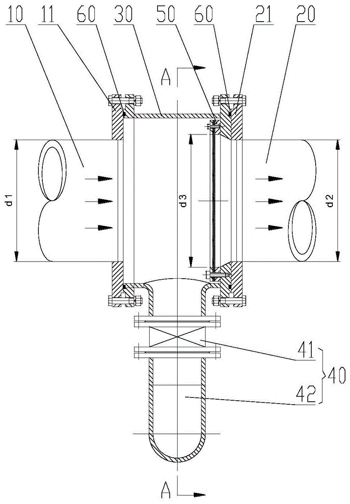
图1示出了根据本发明实施例提供的管道过滤器的结构示意图;1 shows a schematic structural diagram of a pipeline filter provided according to an embodiment of the present invention;
图2示出了图1中A-A处的剖视图;Fig. 2 shows the sectional view at A-A in Fig. 1;
图3示出了图1中本体的结构示意图;Fig. 3 shows the structural schematic diagram of the body in Fig. 1;
图4示出了图3中B-B处的剖视图;Fig. 4 shows the sectional view at B-B in Fig. 3;
图5示出了图1中过滤件的结构示意图;Fig. 5 shows the structural representation of the filter element in Fig. 1;
图6示出了本发明又一实施例提供的过滤件的结构示意图。FIG. 6 shows a schematic structural diagram of a filter element provided by another embodiment of the present invention.
其中,上述附图包括以下附图标记:Wherein, the above-mentioned drawings include the following reference signs:
10、进水管道;11、第一连接部;10. Water inlet pipe; 11. The first connecting part;
20、出水管道;21、第二连接部;20. Water outlet pipe; 21. Second connecting part;
30、本体;31、进水口;32、出水口;33、第三连接部;34、除杂口;30, the body; 31, the water inlet; 32, the water outlet; 33, the third connecting part; 34, the impurity removal port;
40、排污组件;41、控制阀;42、排污管;40. Sewage assembly; 41. Control valve; 42. Sewage pipe;
50、过滤件;51、过滤网;52、压环;53、底环;50, filter element; 51, filter screen; 52, pressure ring; 53, bottom ring;
60、密封件。60. Seals.
具体实施方式Detailed ways
下面将结合本发明实施例中的附图,对本发明实施例中的技术方案进行清楚、完整地描述,显然,所描述的实施例仅仅是本发明一部分实施例,而不是全部的实施例。以下对至少一个示例性实施例的描述实际上仅仅是说明性的,决不作为对本发明及其应用或使用的任何限制。基于本发明中的实施例,本领域普通技术人员在没有作出创造性劳动前提下所获得的所有其他实施例,都属于本发明保护的范围。The technical solutions in the embodiments of the present invention will be clearly and completely described below with reference to the accompanying drawings in the embodiments of the present invention. Obviously, the described embodiments are only a part of the embodiments of the present invention, but not all of the embodiments. The following description of at least one exemplary embodiment is merely illustrative in nature and is in no way intended to limit the invention, its application, or uses. Based on the embodiments of the present invention, all other embodiments obtained by those of ordinary skill in the art without creative efforts shall fall within the protection scope of the present invention.
如图1和图2所示,本申请实施例提供了一种管道过滤器,该管道过滤器包括:进水管道10、出水管道20、本体30、排污组件40以及过滤件50。其中,进水管道10具有第一连接端,第一连接端的侧壁具有第一环形凸台,第一环形凸台上设置有第一连接部11。出水管道20具有第二连接端,第二连接端的侧壁具有第二环形凸台,第二环形凸台上设置有第二连接部21。进水管道10的轴线与出水管道20的轴线相重合,进水管道10和出水管道20的最小直径均为200mm。将进水管道10与出水管道20的轴线设置重合,能够尽可能减少对流体造成的阻力,避免流体在本体30内发生紊流。本体30具有相对设置的进水口31和出水口32,进水口31和出水口32的侧壁上均设置有第三连接部33,进水口31与进水管道10连接,第一连接部11与进水口31上的第三连接部33具有间隔,出水口32与出水管道20连接,第二连接部21与出水口32上的第三连接部33具有间隔。通过设置上述两处间隔,可以避免由于端面的工艺误差而导致端面不平齐、无法贴合,进而导致连接失效的问题出现,提高二者连接的可靠性。本体30的下侧壁上还设置有除杂口34,除杂口34位于进水口31和出水口32之间,该除杂口34用于将本体30内的杂质排出。排污组件40位于本体30的下方,且排污组件40的一端与除杂口34连接,排污组件40的另一端用于排污。过滤件50设置在本体30内,过滤件50用于对从进水口31流至出水口32的流体进行过滤,除杂口34对应过滤件50设置且位于过滤件50的下方,杂质由过滤件50过滤后由除杂口34落入排污组件40内。As shown in FIG. 1 and FIG. 2 , an embodiment of the present application provides a pipeline filter, which includes: a
通过本申请提供的技术方案,该管道过滤器包括进水管道10、出水管道20、本体30、排污组件40以及过滤件50。其中,本体30上设置有进水口31、出水口32以及除杂口34,除杂口34对应过滤件50设置,且位于过滤件50的下方。在使用时,流体在经过过滤件50时,会将杂质过滤出来,过滤出的杂质由除杂口34落入至排污组件40中。通过本申请提供的过滤装置,其结构简单、零部件数量少,便于安装和维修;其能够过滤流体杂质,并且能够将杂质存储在排污组件40中,而不会影响本体30内流体的流通,避免由于杂质过多而堵塞通道的情况发生,增大了杂质的存储空间,进而提高了装置的过滤性能。According to the technical solution provided in this application, the pipeline filter includes a
具体的,该排污组件40包括:控制阀41和排污管42。其中,控制阀41的一端与除杂口34连接,排污管42的一端与控制阀41的另一端连接,排污管42的另一端设置有封盖。通过上述结构,可以在存储杂质时,打开控制阀41,将杂质由过滤件50过滤后经除杂口34落入排污管42中。当需要对排污管42进行清理时,可以关闭控制阀41,打开排污管42的封盖直接清理即可。通过该结构能够省去经常拆卸装置清理杂质的麻烦,并且能够在清理杂质的过程中保证主管道的正常运行。Specifically, the
其中,封盖可通过法兰结构与排污管42可拆卸连接,以便于工作人员进行拆卸。Wherein, the cover can be detachably connected with the
如图2所示,该排污管42包括相互连接的竖直段和水平段,竖直段的一端与控制阀41连接,水平段的端部设置有封盖。通过上述结构,可以便于工作人员对封盖进行拆装操作。当然也可根据需要将排污管42设置为直管结构。As shown in FIG. 2 , the
其中,进水口31与进水管道10之间以及出水口32与出水管道20之间可通过紧固件或其它连接件进行连接。具体在本实施例中,第一连接部11和进水口31上的第三连接部33为相互配合的法兰结构,第二连接部21和出水口32上的第三连接部33为相互配合的法兰结构。其中,在第一连接部11、第二连接部21以及第三连接部33上均环形间隔设置有多个连接孔,紧固件穿设在相对的两个连接孔内以完成连接。The connection between the
其中,过滤件50可以设置在本体30的内壁上。具体在本实施例中,如图3和图4所示,出水口32的内壁上环形设置有装配凸台,过滤件50设置在装配凸台的靠近进水口31的端面上。通过上述结构,可便于对过滤件50进行安装、固定,提高二者连接的稳定性。过滤件50可通过紧固件或焊接方式连接在该装配凸台上。Wherein, the
如图5所示,该过滤件50包括:过滤网51、压环52以及底环53。其中,压环52设置在过滤网51的周缘,且位于过滤网51的靠近进水口31的一侧,底环53设置在过滤网51的周缘,且位于过滤网51的靠近出水口32的一侧,底环53与压环52通过连接件连接,这样即可将过滤网51固定在底环53与压环52之间。As shown in FIG. 5 , the
其中,在本实施例中,过滤网51为平面结构。过滤网51采用不锈钢材料制成,以提高部件的使用寿命。Among them, in this embodiment, the
其中,如图1中d1为进水管道10的管径,d2为出水管道的管径,d3为过滤件的直径。在本实施例中,将过滤件50的直径设置为大于出水管道20的直径,这样可以保证流体均能通过过滤件50过滤后从出水管道20流出,保证过滤效果。Wherein, in Fig. 1 , d1 is the pipe diameter of the
过滤件50位于除杂口34的靠近出水口32的一侧,这样能够便于使杂质落入至除杂口34内,进而便于经过滤件50过滤的杂质由排污组件40排出。The
如图3和图4所示,该除杂口34为管状结构,除杂口34的内径朝远离本体30的方向逐渐缩小。这样可以使除杂口34设计为喇叭口形状,以便于将杂质汇集、引流至下方的排污组件40中。具体的,除杂口34与控制阀41通过法兰结构连接。As shown in FIG. 3 and FIG. 4 , the
其中,第一连接端和进水口31之间以及第二连接端与出水口32之间均设置有密封件60。具体的,在第一连接端的端面或进水口31的端面设置有密封槽,密封件60为密封圈,密封圈放置在密封槽内,通过上述结构对第一连接端和进水口31的连接处进行密封,避免流体泄露。Wherein, seals 60 are provided between the first connection end and the
如图6所示,在本申请的又一实施例中,与上述实施例的不同之处在于,本实施例中,过滤网51为曲形结构,过滤网51具有相对设置的凸面和凹面,凸面朝向出水管道20设置。通过上述结构可以增加过滤网51的过滤面积,提高过滤性能。As shown in FIG. 6 , in another embodiment of the present application, the difference from the above embodiment is that in this embodiment, the
通过本申请提供的管道过滤器,其结构简单、所占空间小,能够在大直径管道中进行安装,无需在安装时对管道进行较大改动。通过设置排污组件40,能够提高杂质的容纳能力,利用控制阀41能够在流体运输的同时实现对杂质进行清理,减少整体拆装维修的次数,极大方便工作人员进行操作。The pipeline filter provided by the present application has a simple structure, occupies a small space, and can be installed in a large-diameter pipeline, without the need for major changes to the pipeline during installation. By arranging the
本装置的工作过程:进水管道内含有杂质的水进入本体,水经过过滤件从出水管道流出,杂质掉入除杂口,这样经过本过滤器后水变得更加纯净,此时控制阀处于打开位置,杂质落入排污管内,经过一段时间过滤,关闭控制阀、打开排污管的封盖,清理管内的杂质,清理干净后拧紧封盖,打开控制阀即可。The working process of the device: the water containing impurities in the water inlet pipe enters the body, the water flows out from the water outlet pipe through the filter element, and the impurities fall into the impurity removal port, so that the water becomes more pure after passing through the filter, and the control valve is at this time. Open position, impurities fall into the sewage pipe, after a period of filtration, close the control valve, open the cover of the sewage pipe, clean the impurities in the pipe, tighten the cover after cleaning, and open the control valve.
本发明的有益效果主要体现在:The beneficial effects of the present invention are mainly reflected in:
1.过滤装置整体径向尺寸小,安装空间小。1. The overall radial dimension of the filter device is small, and the installation space is small.
2.过滤装置具有沉渣功能,并且在主体管路处于工作状态的时候可随时对杂质进行清理。2. The filter device has the function of sedimentation, and can clean up impurities at any time when the main pipeline is in working state.
3.结构简单、维修方便,既可用在新的供水系统中,也可用于旧供水系统的维修保养。3. The structure is simple and the maintenance is convenient, which can be used in both the new water supply system and the maintenance of the old water supply system.
需要注意的是,这里所使用的术语仅是为了描述具体实施方式,而非意图限制根据本申请的示例性实施方式。如在这里所使用的,除非上下文另外明确指出,否则单数形式也意图包括复数形式,此外,还应当理解的是,当在本说明书中使用术语“包含”和/或“包括”时,其指明存在特征、步骤、操作、器件、组件和/或它们的组合。It should be noted that the terminology used herein is for the purpose of describing specific embodiments only, and is not intended to limit the exemplary embodiments according to the present application. As used herein, unless the context clearly dictates otherwise, the singular is intended to include the plural as well, furthermore, it is to be understood that when the terms "comprising" and/or "including" are used in this specification, it indicates that There are features, steps, operations, devices, components and/or combinations thereof.
除非另外具体说明,否则在这些实施例中阐述的部件和步骤的相对布置、数字表达式和数值不限制本发明的范围。同时,应当明白,为了便于描述,附图中所示出的各个部分的尺寸并不是按照实际的比例关系绘制的。对于相关领域普通技术人员已知的技术、方法和设备可能不作详细讨论,但在适当情况下,所述技术、方法和设备应当被视为授权说明书的一部分。在这里示出和讨论的所有示例中,任何具体值应被解释为仅仅是示例性的,而不是作为限制。因此,示例性实施例的其它示例可以具有不同的值。应注意到:相似的标号和字母在下面的附图中表示类似项,因此,一旦某一项在一个附图中被定义,则在随后的附图中不需要对其进行进一步讨论。The relative arrangement of the components and steps, the numerical expressions and numerical values set forth in these embodiments do not limit the scope of the invention unless specifically stated otherwise. Meanwhile, it should be understood that, for the convenience of description, the dimensions of various parts shown in the accompanying drawings are not drawn in an actual proportional relationship. Techniques, methods, and devices known to those of ordinary skill in the relevant art may not be discussed in detail, but where appropriate, such techniques, methods, and devices should be considered part of the authorized description. In all examples shown and discussed herein, any specific value should be construed as illustrative only and not as limiting. Accordingly, other examples of exemplary embodiments may have different values. It should be noted that like numerals and letters refer to like items in the following figures, so once an item is defined in one figure, it does not require further discussion in subsequent figures.
在本发明的描述中,需要理解的是,方位词如“前、后、上、下、左、右”、“横向、竖向、垂直、水平”和“顶、底”等所指示的方位或位置关系通常是基于附图所示的方位或位置关系,仅是为了便于描述本发明和简化描述,在未作相反说明的情况下,这些方位词并不指示和暗示所指的装置或元件必须具有特定的方位或者以特定的方位构造和操作,因此不能理解为对本发明保护范围的限制;方位词“内、外”是指相对于各部件本身的轮廓的内外。In the description of the present invention, it should be understood that the orientations indicated by orientation words such as "front, rear, top, bottom, left, right", "horizontal, vertical, vertical, horizontal" and "top, bottom" etc. Or the positional relationship is usually based on the orientation or positional relationship shown in the drawings, which is only for the convenience of describing the present invention and simplifying the description, and these orientation words do not indicate or imply the indicated device or element unless otherwise stated. It must have a specific orientation or be constructed and operated in a specific orientation, so it cannot be construed as a limitation on the protection scope of the present invention; the orientation words "inside and outside" refer to the inside and outside relative to the outline of each component itself.
为了便于描述,在这里可以使用空间相对术语,如“在……之上”、“在……上方”、“在……上表面”、“上面的”等,用来描述如在图中所示的一个器件或特征与其他器件或特征的空间位置关系。应当理解的是,空间相对术语旨在包含除了器件在图中所描述的方位之外的在使用或操作中的不同方位。例如,如果附图中的器件被倒置,则描述为“在其他器件或构造上方”或“在其他器件或构造之上”的器件之后将被定位为“在其他器件或构造下方”或“在其他器件或构造之下”。因而,示例性术语“在……上方”可以包括“在……上方”和“在……下方”两种方位。该器件也可以其他不同方式定位(旋转90度或处于其他方位),并且对这里所使用的空间相对描述作出相应解释。For ease of description, spatially relative terms, such as "on", "over", "on the surface", "above", etc., may be used herein to describe what is shown in the figures. The spatial positional relationship of one device or feature shown to other devices or features. It should be understood that spatially relative terms are intended to encompass different orientations of the device in use or operation in addition to the orientation depicted in the figures. For example, if the device in the figures is turned over, elements described as "above" or "over" other devices or features would then be oriented "below" or "over" the other devices or features under other devices or constructions". Thus, the exemplary term "above" can encompass both an orientation of "above" and "below." The device may also be otherwise oriented (rotated 90 degrees or at other orientations) and the spatially relative descriptions used herein interpreted accordingly.
此外,需要说明的是,使用“第一”、“第二”等词语来限定零部件,仅仅是为了便于对相应零部件进行区别,如没有另行声明,上述词语并没有特殊含义,因此不能理解为对本发明保护范围的限制。In addition, it should be noted that the use of words such as "first" and "second" to define components is only for the convenience of distinguishing corresponding components. Unless otherwise stated, the above words have no special meaning and therefore cannot be understood to limit the scope of protection of the present invention.
以上所述仅为本发明的优选实施例而已,并不用于限制本发明,对于本领域的技术人员来说,本发明可以有各种更改和变化。凡在本发明的精神和原则之内,所作的任何修改、等同替换、改进等,均应包含在本发明的保护范围之内。The above descriptions are only preferred embodiments of the present invention, and are not intended to limit the present invention. For those skilled in the art, the present invention may have various modifications and changes. Any modification, equivalent replacement, improvement, etc. made within the spirit and principle of the present invention shall be included within the protection scope of the present invention.
Claims (10)
Priority Applications (1)
| Application Number | Priority Date | Filing Date | Title |
|---|---|---|---|
| CN202010302178.7A CN111346420A (en) | 2020-04-16 | 2020-04-16 | Pipeline filter |
Applications Claiming Priority (1)
| Application Number | Priority Date | Filing Date | Title |
|---|---|---|---|
| CN202010302178.7A CN111346420A (en) | 2020-04-16 | 2020-04-16 | Pipeline filter |
Publications (1)
| Publication Number | Publication Date |
|---|---|
| CN111346420A true CN111346420A (en) | 2020-06-30 |
Family
ID=71189582
Family Applications (1)
| Application Number | Title | Priority Date | Filing Date |
|---|---|---|---|
| CN202010302178.7A Pending CN111346420A (en) | 2020-04-16 | 2020-04-16 | Pipeline filter |
Country Status (1)
| Country | Link |
|---|---|
| CN (1) | CN111346420A (en) |
Cited By (4)
| Publication number | Priority date | Publication date | Assignee | Title |
|---|---|---|---|---|
| CN113907016A (en) * | 2021-09-30 | 2022-01-11 | 内蒙古慧羊生物科技有限公司 | A kind of preventing debris from clogging livestock drinking water system |
| CN114146470A (en) * | 2021-12-03 | 2022-03-08 | 深圳市德龙智能高科技有限公司 | Sewage filtering device and sewage filtering equipment |
| CN114480761A (en) * | 2021-12-17 | 2022-05-13 | 中国华冶科工集团有限公司 | Blast furnace soft water closed cycle cooling system and method |
| CN115006907A (en) * | 2022-06-24 | 2022-09-06 | 彩虹(延安)新能源有限公司 | Pipeline filter device |
Citations (4)
| Publication number | Priority date | Publication date | Assignee | Title |
|---|---|---|---|---|
| KR100765917B1 (en) * | 2007-01-30 | 2007-10-10 | 여세현 | Apparatus for manufacturing network of vibrating sorter |
| CN203916253U (en) * | 2014-05-29 | 2014-11-05 | 山东国泰创新供水技术有限公司 | A kind of straight-through type filter |
| CN210078975U (en) * | 2019-05-22 | 2020-02-18 | 淮南矿业(集团)有限责任公司 | Dustproof filter |
| CN212214823U (en) * | 2020-04-16 | 2020-12-25 | 衡阳华菱钢管有限公司 | Pipeline filter |
-
2020
- 2020-04-16 CN CN202010302178.7A patent/CN111346420A/en active Pending
Patent Citations (4)
| Publication number | Priority date | Publication date | Assignee | Title |
|---|---|---|---|---|
| KR100765917B1 (en) * | 2007-01-30 | 2007-10-10 | 여세현 | Apparatus for manufacturing network of vibrating sorter |
| CN203916253U (en) * | 2014-05-29 | 2014-11-05 | 山东国泰创新供水技术有限公司 | A kind of straight-through type filter |
| CN210078975U (en) * | 2019-05-22 | 2020-02-18 | 淮南矿业(集团)有限责任公司 | Dustproof filter |
| CN212214823U (en) * | 2020-04-16 | 2020-12-25 | 衡阳华菱钢管有限公司 | Pipeline filter |
Cited By (5)
| Publication number | Priority date | Publication date | Assignee | Title |
|---|---|---|---|---|
| CN113907016A (en) * | 2021-09-30 | 2022-01-11 | 内蒙古慧羊生物科技有限公司 | A kind of preventing debris from clogging livestock drinking water system |
| CN114146470A (en) * | 2021-12-03 | 2022-03-08 | 深圳市德龙智能高科技有限公司 | Sewage filtering device and sewage filtering equipment |
| CN114146470B (en) * | 2021-12-03 | 2023-01-10 | 深圳市德龙智能高科技有限公司 | A kind of sewage filtering device and sewage filtering equipment |
| CN114480761A (en) * | 2021-12-17 | 2022-05-13 | 中国华冶科工集团有限公司 | Blast furnace soft water closed cycle cooling system and method |
| CN115006907A (en) * | 2022-06-24 | 2022-09-06 | 彩虹(延安)新能源有限公司 | Pipeline filter device |
Similar Documents
| Publication | Publication Date | Title |
|---|---|---|
| US11969675B2 (en) | Inline-type strainer | |
| CN108837574A (en) | Novel basket type filter | |
| CN212440342U (en) | Pipeline filtering device | |
| CN111442107A (en) | Filter valve for easy cleaning | |
| CN212854915U (en) | Maintenance-free automatic pollution discharge straight-through type micro-resistance filter | |
| CN219493107U (en) | Pipeline gate valve convenient to dismouting | |
| CN212214823U (en) | Pipeline filter | |
| CN213773718U (en) | An outdoor anti-blocking floor drain | |
| CN110180249A (en) | Quick union of the soft water control valve with prefilter | |
| CN210078975U (en) | Dustproof filter | |
| CN208859100U (en) | Ultrahigh-strength corrosion-resistant oil sea water desalination biphase stainless steel tubing | |
| CN209771551U (en) | a cartridge filter | |
| CN222657923U (en) | Filtering device and energy storage equipment | |
| CN210397865U (en) | An anti-clogging flow controller | |
| CN209909273U (en) | Solenoid valve with filter equipment | |
| CN209354852U (en) | A kind of valve with alternate configuration | |
| CN207470913U (en) | A kind of restrictor ring mounting structure | |
| CN112044161A (en) | Maintenance-free automatic pollution discharge straight-through type micro-resistance filter | |
| CN224033355U (en) | Hydraulic element anti-blocking mechanism in heat dissipation fluid circulation system | |
| CN220834429U (en) | Filtering structure and pipeline | |
| CN221296819U (en) | Industrial gas pipeline filter equipment | |
| CN223464537U (en) | An angular filtering device | |
| CN208511995U (en) | A new type of basket filter | |
| CN222738616U (en) | High pressure filter with integral filter cartridge | |
| CN219399267U (en) | self-cleaning line filter |
Legal Events
| Date | Code | Title | Description |
|---|---|---|---|
| PB01 | Publication | ||
| PB01 | Publication | ||
| SE01 | Entry into force of request for substantive examination | ||
| SE01 | Entry into force of request for substantive examination | ||
| RJ01 | Rejection of invention patent application after publication | ||
| RJ01 | Rejection of invention patent application after publication |
Application publication date: 20200630 |