CN111331030A - An intelligent profile punching equipment - Google Patents
An intelligent profile punching equipment Download PDFInfo
- Publication number
- CN111331030A CN111331030A CN202010205409.2A CN202010205409A CN111331030A CN 111331030 A CN111331030 A CN 111331030A CN 202010205409 A CN202010205409 A CN 202010205409A CN 111331030 A CN111331030 A CN 111331030A
- Authority
- CN
- China
- Prior art keywords
- punching
- clamping
- translation
- shaped mounting
- frame
- Prior art date
- Legal status (The legal status is an assumption and is not a legal conclusion. Google has not performed a legal analysis and makes no representation as to the accuracy of the status listed.)
- Withdrawn
Links
Images



Classifications
-
- B—PERFORMING OPERATIONS; TRANSPORTING
- B21—MECHANICAL METAL-WORKING WITHOUT ESSENTIALLY REMOVING MATERIAL; PUNCHING METAL
- B21D—WORKING OR PROCESSING OF SHEET METAL OR METAL TUBES, RODS OR PROFILES WITHOUT ESSENTIALLY REMOVING MATERIAL; PUNCHING METAL
- B21D28/00—Shaping by press-cutting; Perforating
- B21D28/24—Perforating, i.e. punching holes
- B21D28/34—Perforating tools; Die holders
-
- B—PERFORMING OPERATIONS; TRANSPORTING
- B08—CLEANING
- B08B—CLEANING IN GENERAL; PREVENTION OF FOULING IN GENERAL
- B08B15/00—Preventing escape of dirt or fumes from the area where they are produced; Collecting or removing dirt or fumes from that area
- B08B15/04—Preventing escape of dirt or fumes from the area where they are produced; Collecting or removing dirt or fumes from that area from a small area, e.g. a tool
-
- B—PERFORMING OPERATIONS; TRANSPORTING
- B21—MECHANICAL METAL-WORKING WITHOUT ESSENTIALLY REMOVING MATERIAL; PUNCHING METAL
- B21C—MANUFACTURE OF METAL SHEETS, WIRE, RODS, TUBES, PROFILES OR LIKE SEMI-MANUFACTURED PRODUCTS OTHERWISE THAN BY ROLLING; AUXILIARY OPERATIONS USED IN CONNECTION WITH METAL-WORKING WITHOUT ESSENTIALLY REMOVING MATERIAL
- B21C51/00—Measuring, gauging, indicating, counting, or marking devices specially adapted for use in the production or manipulation of material in accordance with subclasses B21B - B21F
-
- B—PERFORMING OPERATIONS; TRANSPORTING
- B21—MECHANICAL METAL-WORKING WITHOUT ESSENTIALLY REMOVING MATERIAL; PUNCHING METAL
- B21D—WORKING OR PROCESSING OF SHEET METAL OR METAL TUBES, RODS OR PROFILES WITHOUT ESSENTIALLY REMOVING MATERIAL; PUNCHING METAL
- B21D43/00—Feeding, positioning or storing devices combined with, or arranged in, or specially adapted for use in connection with, apparatus for working or processing sheet metal, metal tubes or metal profiles; Associations therewith of cutting devices
- B21D43/003—Positioning devices
-
- B—PERFORMING OPERATIONS; TRANSPORTING
- B21—MECHANICAL METAL-WORKING WITHOUT ESSENTIALLY REMOVING MATERIAL; PUNCHING METAL
- B21D—WORKING OR PROCESSING OF SHEET METAL OR METAL TUBES, RODS OR PROFILES WITHOUT ESSENTIALLY REMOVING MATERIAL; PUNCHING METAL
- B21D43/00—Feeding, positioning or storing devices combined with, or arranged in, or specially adapted for use in connection with, apparatus for working or processing sheet metal, metal tubes or metal profiles; Associations therewith of cutting devices
- B21D43/20—Storage arrangements; Piling or unpiling
-
- B—PERFORMING OPERATIONS; TRANSPORTING
- B26—HAND CUTTING TOOLS; CUTTING; SEVERING
- B26D—CUTTING; DETAILS COMMON TO MACHINES FOR PERFORATING, PUNCHING, CUTTING-OUT, STAMPING-OUT OR SEVERING
- B26D5/00—Arrangements for operating and controlling machines or devices for cutting, cutting-out, stamping-out, punching, perforating, or severing by means other than cutting
- B26D5/08—Means for actuating the cutting member to effect the cut
- B26D5/086—Electric, magnetic, piezoelectric, electro-magnetic means
-
- B—PERFORMING OPERATIONS; TRANSPORTING
- B26—HAND CUTTING TOOLS; CUTTING; SEVERING
- B26D—CUTTING; DETAILS COMMON TO MACHINES FOR PERFORATING, PUNCHING, CUTTING-OUT, STAMPING-OUT OR SEVERING
- B26D7/00—Details of apparatus for cutting, cutting-out, stamping-out, punching, perforating, or severing by means other than cutting
- B26D7/01—Means for holding or positioning work
- B26D7/02—Means for holding or positioning work with clamping means
-
- B—PERFORMING OPERATIONS; TRANSPORTING
- B26—HAND CUTTING TOOLS; CUTTING; SEVERING
- B26D—CUTTING; DETAILS COMMON TO MACHINES FOR PERFORATING, PUNCHING, CUTTING-OUT, STAMPING-OUT OR SEVERING
- B26D7/00—Details of apparatus for cutting, cutting-out, stamping-out, punching, perforating, or severing by means other than cutting
- B26D7/18—Means for removing cut-out material or waste
-
- B—PERFORMING OPERATIONS; TRANSPORTING
- B26—HAND CUTTING TOOLS; CUTTING; SEVERING
- B26D—CUTTING; DETAILS COMMON TO MACHINES FOR PERFORATING, PUNCHING, CUTTING-OUT, STAMPING-OUT OR SEVERING
- B26D7/00—Details of apparatus for cutting, cutting-out, stamping-out, punching, perforating, or severing by means other than cutting
- B26D7/26—Means for mounting or adjusting the cutting member; Means for adjusting the stroke of the cutting member
- B26D7/2614—Means for mounting the cutting member
-
- B—PERFORMING OPERATIONS; TRANSPORTING
- B26—HAND CUTTING TOOLS; CUTTING; SEVERING
- B26D—CUTTING; DETAILS COMMON TO MACHINES FOR PERFORATING, PUNCHING, CUTTING-OUT, STAMPING-OUT OR SEVERING
- B26D7/00—Details of apparatus for cutting, cutting-out, stamping-out, punching, perforating, or severing by means other than cutting
- B26D7/26—Means for mounting or adjusting the cutting member; Means for adjusting the stroke of the cutting member
- B26D7/2628—Means for adjusting the position of the cutting member
-
- B—PERFORMING OPERATIONS; TRANSPORTING
- B26—HAND CUTTING TOOLS; CUTTING; SEVERING
- B26F—PERFORATING; PUNCHING; CUTTING-OUT; STAMPING-OUT; SEVERING BY MEANS OTHER THAN CUTTING
- B26F1/00—Perforating; Punching; Cutting-out; Stamping-out; Apparatus therefor
- B26F1/02—Perforating by punching, e.g. with relatively-reciprocating punch and bed
- B26F1/14—Punching tools; Punching dies
-
- B—PERFORMING OPERATIONS; TRANSPORTING
- B26—HAND CUTTING TOOLS; CUTTING; SEVERING
- B26D—CUTTING; DETAILS COMMON TO MACHINES FOR PERFORATING, PUNCHING, CUTTING-OUT, STAMPING-OUT OR SEVERING
- B26D7/00—Details of apparatus for cutting, cutting-out, stamping-out, punching, perforating, or severing by means other than cutting
- B26D2007/0012—Details, accessories or auxiliary or special operations not otherwise provided for
- B26D2007/0018—Trays, reservoirs for waste, chips or cut products
Landscapes
- Engineering & Computer Science (AREA)
- Mechanical Engineering (AREA)
- Life Sciences & Earth Sciences (AREA)
- Forests & Forestry (AREA)
- Perforating, Stamping-Out Or Severing By Means Other Than Cutting (AREA)
Abstract
本发明公开了冲孔设备技术领域的一种智能型材冲孔设备,包括主机架,主机架包括主机柜以及设置于主机柜顶部后侧的安装架,主机柜的内腔设置有两组沿主机柜长度方向及间隔分布的定位夹持机构,主机柜的顶部设置有定位测距机构,安装架的前侧安装有平移机构,平移机构前侧安装有冲孔机构,主机柜的顶面嵌设有角料收集机构,本发明提供了一种智能型材冲孔设备,可用于自动装夹型材和自动检测安装位置,可实现在一条直线上进行连续加工,可快速清理收集槽中的角料,本设备具有加工效率快、精度高和易清洁的优点。
The invention discloses an intelligent profile punching equipment in the technical field of punching equipment. The positioning and clamping mechanism in the length direction and interval distribution of the cabinet, the top of the main cabinet is provided with a positioning and distance measuring mechanism, the front side of the mounting frame is installed with a translation mechanism, the front side of the translation mechanism is installed with a punching mechanism, and the top surface of the main cabinet is embedded with With a corner material collection mechanism, the present invention provides an intelligent profile punching equipment, which can be used for automatic clamping of profiles and automatic detection of installation positions, which can realize continuous processing on a straight line, and can quickly clean the corner materials in the collection tank. This equipment has the advantages of fast processing efficiency, high precision and easy cleaning.
Description
技术领域technical field
本发明涉及冲孔设备技术领域,具体为一种智能型材冲孔设备。The invention relates to the technical field of punching equipment, in particular to an intelligent profile punching equipment.
背景技术Background technique
冲孔是指在钢板、革、布、木板等材料上打出各种图形以适应不同的需求,冲孔加工方式包括液压成形,液压成形工艺成形的零件具有节省材料、降低成本、性能好等优点。随着液压成形零件的大量使用。液压冲孔作为一种新型的冲裁方法,对空心零件、轴线为曲线的零件进行冲孔,具有传统加工工艺无法比拟的优点。液压冲孔在整个冲孔过程中不需要凹模,这对于解决由于内部尺寸过小、或者轴线为曲线而导致内部不能安放凹模的零件加工具有很大优势。同时,利用液压冲孔替代激光切孔,对降低零件生产成本,提高生产效率具有重要作用。Punching refers to punching various graphics on steel, leather, cloth, wood and other materials to meet different needs. The punching process includes hydroforming. The parts formed by the hydroforming process have the advantages of saving materials, reducing costs, and good performance. . With the massive use of hydroformed parts. As a new type of punching method, hydraulic punching can punch hollow parts and parts with a curved axis, which has incomparable advantages in traditional processing technology. Hydraulic punching does not require a die during the entire punching process, which has great advantages for processing parts that cannot be placed inside a die due to too small internal dimensions or a curved axis. At the same time, the use of hydraulic punching instead of laser cutting plays an important role in reducing the production cost of parts and improving production efficiency.
如图11所示的一种长条状的型材A,型材A的顶面沿长度方向居中开设有通孔B,其中通孔B包括多种不同孔径通过一定规律交错排列,传统加工时,首先需要将型材A通过专门的夹具固定安装在冲孔设备的工作台上,接着在型材A的顶面进行标记冲压位置,接着在冲孔设备的主轴上安装其中一种孔径尺寸的冲头,并在该尺寸通孔所在位置进行冲压,冲完该尺寸通孔后换用另一种尺寸的冲头进行冲压另一种尺寸的通孔,整个冲压过程不仅步骤繁琐、效率低下,而且每次装夹和标记孔位都需要人工手动进行,尤其对于批量生产的工件,很难保持产品尺寸的加工精度和均一性。As shown in Figure 11, a long profile A has a through hole B in the middle of the top surface of the profile A along the length direction. The through hole B includes a variety of different apertures and is staggered with a certain regularity. During traditional processing, first of all The profile A needs to be fixedly installed on the workbench of the punching equipment through a special fixture, then mark the punching position on the top surface of the profile A, and then install one of the hole size punches on the main shaft of the punching equipment, and Stamping is performed at the location where the through hole of this size is located, and after punching the through hole of this size, a punch of another size is used to punch the through hole of another size. Clamping and marking holes all need to be done manually, especially for mass-produced workpieces, it is difficult to maintain the machining accuracy and uniformity of product dimensions.
基于此,发明设计了一种智能型材冲孔设备,以解决上述问题。Based on this, the invention designs an intelligent profile punching equipment to solve the above problems.
发明内容SUMMARY OF THE INVENTION
发明的目的在于提供一种智能型材冲孔设备,以解决上述技术问题。The purpose of the invention is to provide an intelligent profile punching equipment to solve the above technical problems.
为实现上述目的,发明提供如下技术方案:一种智能型材冲孔设备,包括主机架,所述主机架包括主机柜以及设置于所述主机柜顶部后侧的安装架,所述主机柜的内腔设置有两组沿主机柜长度方向及间隔分布的定位夹持机构,所述主机柜的顶部设置有定位测距机构,所述安装架的前侧安装有平移机构,所述平移机构前侧安装有冲孔机构,所述主机柜的顶面嵌设有角料收集机构。In order to achieve the above purpose, the invention provides the following technical solutions: an intelligent profile punching equipment, including a main frame, the main frame includes a main cabinet and a mounting frame arranged on the rear side of the top of the main cabinet, the inner part of the main cabinet is The cavity is provided with two sets of positioning and clamping mechanisms distributed along the length of the main cabinet and at intervals. The top of the main cabinet is provided with a positioning and ranging mechanism, and the front side of the mounting frame is installed with a translation mechanism. The front side of the translation mechanism A punching mechanism is installed, and a scrap collecting mechanism is embedded on the top surface of the main cabinet.
优选的,所述主机柜的顶面沿长度方向居中开设有角料下落槽,所述角料收集机构嵌设在所述角料下落槽中,所述角料下落槽的两侧开设有夹持让位槽,所述定位夹持机构的夹持端通过夹持让位槽伸出所述主机柜的顶面,所述主机柜的顶部安装有触控屏。Preferably, the top surface of the main cabinet is provided with a leftover material drop groove in the center along the length direction, the leftover material collection mechanism is embedded in the leftover material drop groove, and clips are provided on both sides of the leftover material dropout groove. A holding and letting slot, the clamping end of the positioning and clamping mechanism protrudes from the top surface of the main cabinet through the holding and letting slot, and a touch screen is installed on the top of the main cabinet.
优选的,所述定位夹持机构包括U形安装框,所述U形安装框的两侧顶端与所述主机柜的内腔顶部固定安装,所述U形安装框的内腔中部固设有齿轮传动箱,所述齿轮传动箱的前侧安装有夹持电机,所述齿轮传动箱的左右两侧对称设置有夹持丝杆,所述夹持丝杆的另一端与所述U形安装框的侧壁转动安装,所述夹持丝杆的外壁螺接有夹持螺母座,所述夹持螺母座的底部滑动连接有夹持滑轨,所述夹持滑轨固定安装在所述U形安装框内腔底部,所述夹持螺母座的顶部通过夹持连杆连接有夹持块。Preferably, the positioning and clamping mechanism includes a U-shaped mounting frame, the top ends of the two sides of the U-shaped mounting frame are fixedly mounted on the top of the inner cavity of the main cabinet, and the middle of the inner cavity of the U-shaped mounting frame is fixed with Gear transmission box, a clamping motor is installed on the front side of the gear transmission box, clamping screw rods are symmetrically arranged on the left and right sides of the gear transmission box, and the other end of the clamping screw rod is installed with the U-shaped The side wall of the frame is rotated and installed, the outer wall of the clamping screw is screwed with a clamping nut seat, and the bottom of the clamping nut seat is slidably connected with a clamping slide rail, and the clamping slide rail is fixedly installed on the At the bottom of the inner cavity of the U-shaped mounting frame, the top of the clamping nut seat is connected with a clamping block through a clamping link.
优选的,所述齿轮传动箱包括齿轮箱体,所述齿轮箱体的内腔中部设置有主动齿轮,所述主动齿轮与所述夹持电机输出端套接,所述主动齿轮的两侧各啮合设置有从动齿轮,两个所述从动齿轮分别与两侧所述夹持丝杆相套接。Preferably, the gear transmission case includes a gear case body, a driving gear is arranged in the middle of the inner cavity of the gear case body, the driving gear is sleeved with the output end of the clamping motor, and the two sides of the driving gear are respectively A driven gear is meshed and arranged, and the two driven gears are respectively sleeved with the clamping screw rods on both sides.
优选的,所述定位测距机构包括左右相对设置有的L形安装座和L形抵挡座,所述L形安装座的内侧设置有接触板,所述接触板的外侧壁固接有两根相互平行的测距滑杆,所述测距滑杆的外侧贯穿所述L形安装座并与其滑动连接,所述所述测距滑杆的外侧端设置有限位螺钉,所述测距滑杆的外壁套设有压缩弹簧,所述压缩弹簧抵接在所述L形安装座和接触板之间,所述L形安装座上且位于两根所述测距滑杆之间嵌设安装有激光测距传感器,所述接触板上开设有与所述激光测距传感器相对应的检测孔。Preferably, the positioning and distance-measuring mechanism includes an L-shaped mounting seat and an L-shaped resisting seat that are oppositely arranged on the left and right sides, a contact plate is arranged on the inner side of the L-shaped mounting seat, and the outer side wall of the contact plate is fixed with two The distance measuring slide bars are parallel to each other, the outer side of the distance measuring slide bar penetrates through the L-shaped mounting seat and is slidably connected with it, the outer end of the distance measuring slide bar is provided with a limit screw, and the distance measuring slide bar is The outer wall is sleeved with a compression spring, the compression spring abuts between the L-shaped mounting seat and the contact plate, and the L-shaped mounting seat is embedded and installed between the two distance measuring slide bars. For a laser ranging sensor, the contact plate is provided with a detection hole corresponding to the laser ranging sensor.
优选的,所述平移机构包括安装底板,所述安装底板的前侧沿长度方向平行设置有两根平移滑轨,两组所述平移滑轨之间安装有固定齿条,所述平移滑轨的前侧通过平移滑块设置有平移安装板,所述冲孔机构安装在所述平移安装板上,所述平移安装板上一侧安装有平移电机,所述平移电机的后侧输出端通过所述平移安装板固定套接有主动齿轮,所述主动齿轮与所述固定齿条相啮合。Preferably, the translation mechanism includes an installation base plate, two translation slide rails are arranged parallel to the front side of the installation base plate along the length direction, a fixed rack is installed between the two sets of the translation slide rails, and the translation slide rails The front side is provided with a translational mounting plate through the translational slider, the punching mechanism is mounted on the translational mounting plate, a translational motor is installed on one side of the translational mounting plate, and the rear output end of the translational motor passes through the The translation mounting plate is fixedly sleeved with a driving gear, and the driving gear is engaged with the fixed rack.
优选的,所述冲孔机构包括安装在所述平移机构上的直角安装座,所述直角安装座上安装有冲孔液压缸,所述冲孔气缸的底部伸缩端连接有U形安装架,所述U形安装架的顶部两侧固设有冲孔滑杆,所述冲孔滑杆上端贯穿所述直角安装座并与其滑动连接,所述U形安装架的内腔安装有冲头固定块,所述冲头固定块的四周均分别安装有规格不同的冲头,所述冲头固定块通过冲孔转轴与所述U形安装架侧壁转动安装,所述U形安装架的背面安装有用于驱动所述冲头固定块转动切换的冲孔电机。Preferably, the punching mechanism includes a right-angle mounting seat mounted on the translation mechanism, a punching hydraulic cylinder is mounted on the right-angle mounting seat, and a U-shaped mounting frame is connected to the telescopic end of the bottom of the punching cylinder, A punching sliding rod is fixed on both sides of the top of the U-shaped mounting frame, the upper end of the punching sliding rod penetrates the right-angle mounting seat and is slidably connected with it, and a punch is installed in the inner cavity of the U-shaped mounting frame to fix it. The punch fixing block is respectively equipped with punches of different specifications around the punch fixing block. The punch fixing block is rotatably installed with the side wall of the U-shaped mounting frame through the punching shaft. The back of the U-shaped mounting frame A punching motor for driving the rotation and switching of the punch fixing block is installed.
优选的,所述冲头与所述冲头固定块通过螺接固定安装,所述冲头自上而下由螺杆部、卡持部和冲孔部组成,所述卡持部的侧壁四面开设有与扳手配合的平槽结构,所述冲孔部的上小下大的锥状结构。Preferably, the punch and the punch fixing block are fixedly installed by screwing, and the punch is composed of a screw part, a clamping part and a punching part from top to bottom, and the side wall of the clamping part has four sides. A flat groove structure matched with a wrench is provided, and the upper part of the punching part has a small conical structure and a large lower part.
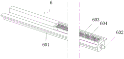
优选的,所述角料收集机构包括安装在所述角料下落槽下方的收集槽和嵌设在所述角料下落槽内腔的刷毛框,所述收集槽的一端开放并伸出所述主机柜的内腔,所述收集槽的另一端安装有气管接头,所述收集槽的上方设置有刷毛框,所述刷毛框的长度方向两侧内壁密布固设有尼龙刷毛。Preferably, the scrap collecting mechanism comprises a collecting slot installed under the scrap dropping slot and a bristle frame embedded in the inner cavity of the scrap dropping slot, one end of the collecting slot is open and protrudes out of the In the inner cavity of the main cabinet, the other end of the collection tank is installed with a gas pipe joint, a brush frame is arranged above the collection tank, and nylon brush bristles are densely fixed on the inner walls of both sides in the length direction of the brush frame.
与现有技术相比,发明的有益效果为:Compared with the prior art, the beneficial effects of the invention are:
本发明主要包括主机架、定位夹持机构、定位测距机构、平移机构、冲孔机构和角料收集机构等机构,其中,定位夹持机构和定位测距机构可用于自动装夹型材和自动检测安装位置,以方便设备控制系统获知冲压位置,通过平移机构和冲孔机构相配合,可实现在一条直线上进行连续加工,并且冲孔机构中U形安装架的背面安装有用于驱动冲头固定块转动切换的冲孔电机,加工过程中通过冲孔电机驱动冲头固定块旋转切换不同的冲头以实现不同孔径一次性加工,免除传统冲压设备换刀重新对位的步骤,角料收集机构设置在主机柜内腔顶部,可用于收集加工过程中产生的角料,收集槽一端的气管接头可与外部压缩空气管连通,通过通入压缩空气可快速清理收集槽中的角料,本设备具有加工效率快、精度高和易清洁的优点。The invention mainly includes a main frame, a positioning and clamping mechanism, a positioning distance measuring mechanism, a translation mechanism, a punching mechanism, a corner material collecting mechanism and other mechanisms, wherein the positioning clamping mechanism and the positioning distance measuring mechanism can be used for automatic clamping of profiles and automatic Detect the installation position to facilitate the equipment control system to know the punching position. Through the cooperation of the translation mechanism and the punching mechanism, continuous processing can be realized in a straight line, and the back of the U-shaped mounting frame in the punching mechanism is equipped with a punch for driving the punch. The punching motor that the fixed block rotates and switches. During the processing process, the punching motor drives the fixed block of the punch to rotate and switch different punches to achieve one-time processing of different apertures, eliminating the steps of traditional punching equipment for tool change and realignment, and scrap collection. The mechanism is set on the top of the inner cavity of the main cabinet, which can be used to collect the scraps generated during the processing. The air pipe joint at one end of the collecting tank can be connected with the external compressed air pipe, and the scraps in the collecting tank can be quickly cleaned by passing in the compressed air. The equipment has the advantages of fast processing efficiency, high precision and easy cleaning.
附图说明Description of drawings
为了更清楚地说明发明实施例的技术方案,下面将对实施例描述所需要使用的附图作简单地介绍,显而易见地,下面描述中的附图仅仅是发明的一些实施例,对于本领域普通技术人员来讲,在不付出创造性劳动的前提下,还可以根据这些附图获得其他的附图。In order to illustrate the technical solutions of the embodiments of the invention more clearly, the following briefly introduces the accompanying drawings used in the description of the embodiments. Obviously, the accompanying drawings in the following description are only some embodiments of the invention, which are not suitable for ordinary people in the art. As far as technical personnel are concerned, other drawings can also be obtained based on these drawings without any creative effort.
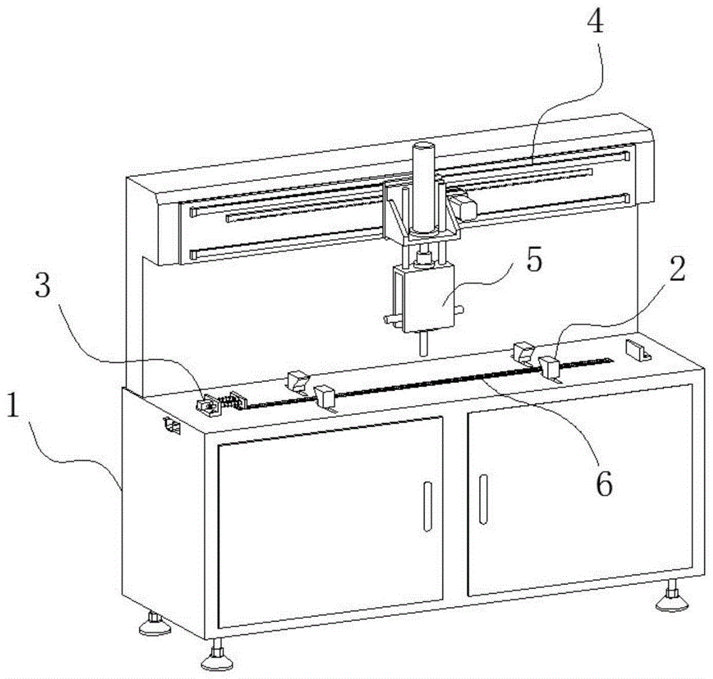
图1为本发明整体结构示意图;Fig. 1 is the overall structure schematic diagram of the present invention;
图2为本发明整体截面结构示意图;2 is a schematic diagram of the overall cross-sectional structure of the present invention;
图3为本发明主机柜结构示意图;3 is a schematic structural diagram of the main cabinet of the present invention;
图4为本发明定位夹持机构结构示意图;4 is a schematic structural diagram of the positioning and clamping mechanism of the present invention;
图5为本发明齿轮传动箱结构示意图;FIG. 5 is a schematic structural diagram of the gear transmission box of the present invention;
图6为本发明定位测距机构结构示意图;6 is a schematic structural diagram of a positioning and ranging mechanism of the present invention;
图7为本发明平移机构结构示意图;7 is a schematic structural diagram of a translation mechanism of the present invention;
图8为本发明冲孔机构结构示意图;Figure 8 is a schematic structural diagram of the punching mechanism of the present invention;
图9为本发明冲头安装结构示意图Figure 9 is a schematic diagram of the installation structure of the punch according to the present invention
图10为本发明角料收集机构结构示意图;Fig. 10 is the structural representation of scrap collecting mechanism of the present invention;
图11为型材A结构示意图。Figure 11 is a schematic diagram of the structure of the profile A.
附图中,各标号所代表的部件列表如下:In the accompanying drawings, the list of components represented by each number is as follows:
1-主机架,2-定位夹持机构,3-定位测距机构,4-平移机构,5-冲孔机构,6-角料收集机构;1-main frame, 2-positioning and clamping mechanism, 3-positioning distance measuring mechanism, 4-translation mechanism, 5-punching mechanism, 6-corner material collection mechanism;
101-主机柜,102-安装架,103-角料下落槽,104-夹持让位槽,105-触控屏;101-main cabinet, 102-installation frame, 103-angle material drop slot, 104-clamping slot, 105-touch screen;
201-U形安装框,202-齿轮传动箱,203-夹持电机,204-夹持丝杆,205-夹持螺母座,206-夹持滑轨,207-夹持连杆,208-夹持块,209-齿轮箱体,210-主动齿轮,211-从动齿轮;201-U-shaped mounting frame, 202-Gear transmission box, 203-Clamping motor, 204-Clamping screw, 205-Clamping nut seat, 206-Clamping slide rail, 207-Clamping link, 208-Clamp Holding block, 209-gear box body, 210-drive gear, 211-driven gear;
301-L形安装座,302-L形抵挡座,303-接触板,304-测距滑杆,305-限位螺钉,306-压缩弹簧,307-激光测距传感器,308-检测孔;301-L-shaped mounting seat, 302-L-shaped blocking seat, 303-contact plate, 304-distance measuring slide bar, 305-limit screw, 306-compression spring, 307-laser distance measuring sensor, 308-detection hole;
401-安装底板,402-平移滑轨,403-固定齿条,404-平移滑块,405-平移安装板,406-平移电机,407-主动齿轮;401-installation base plate, 402-translation slide rail, 403-fixed rack, 404-translation slider, 405-translation mounting plate, 406-translation motor, 407-drive gear;
501-直角安装座,502-冲孔液压缸,503-U形安装架,504-冲孔滑杆,505-冲头固定块,506-冲头,507-冲孔转轴,508-冲孔电机,509-螺杆部,510-卡持部,511-冲孔部;501-Right-Angle Mounting Block, 502-Punching Hydraulic Cylinder, 503-U-Shaped Mounting Frame, 504-Punching Slide Rod, 505-Punch Fixing Block, 506-Punch, 507-Punching Shaft, 508-Punching Motor , 509-screw part, 510-holding part, 511-punching part;
601-收集槽,602-气管接头,603-刷毛框,604-尼龙刷毛。601-collection tank, 602-trachea connector, 603-bristle frame, 604-nylon bristle.
具体实施方式Detailed ways
下面将结合发明实施例中的附图,对发明实施例中的技术方案进行清楚、完整地描述,显然,所描述的实施例仅仅是发明一部分实施例,而不是全部的实施例。基于发明中的实施例,本领域普通技术人员在没有作出创造性劳动前提下所获得的所有其它实施例,都属于发明保护的范围。The technical solutions in the embodiments of the invention will be clearly and completely described below with reference to the drawings in the embodiments of the invention. Obviously, the described embodiments are only a part of the embodiments of the invention, not all of the embodiments. Based on the embodiments in the invention, all other embodiments obtained by those of ordinary skill in the art without creative work fall within the scope of protection of the invention.
请参阅图1-2,发明提供一种技术方案:一种智能型材冲孔设备,包括主机架1,主机架1包括主机柜101以及设置于主机柜101顶部后侧的安装架102,主机柜101的内腔设置有两组沿主机柜101长度方向及间隔分布的定位夹持机构2,主机柜101的顶部设置有定位测距机构3,安装架102的前侧安装有平移机构4,平移机构4前侧安装有冲孔机构5,主机柜101的顶面嵌设有角料收集机构6。1-2, the invention provides a technical solution: an intelligent profile punching equipment, including a
实施例1:Embodiment 1:
进一步的,如图3所示,主机柜101的顶面沿长度方向居中开设有角料下落槽103,角料下落槽103的宽度大于冲头506的最大直径,角料收集机构6嵌设在角料下落槽103中,角料下落槽103的两侧开设有夹持让位槽104,定位夹持机构2的夹持端通过夹持让位槽104伸出主机柜101的顶面,主机柜101的顶部安装有触控屏105,触控屏105与设备的控制系统相连,用于操控设备运作。Further, as shown in FIG. 3 , the top surface of the
实施例2:Example 2:
进一步的,如图4-5所示,定位夹持机构2包括U形安装框201,U形安装框201的两侧顶端与主机柜101的内腔顶部固定安装,U形安装框201的内腔中部固设有齿轮传动箱202,齿轮传动箱202的前侧安装有夹持电机203,夹持电机203前端带有减速器,齿轮传动箱202的左右两侧对称设置有夹持丝杆204,夹持丝杆204与齿轮传动箱202安装处设置有轴承,夹持丝杆204的另一端与U形安装框201的侧壁通过轴承转动安装,夹持丝杆204的外壁螺接有夹持螺母座205,夹持螺母座205的底部滑动连接有夹持滑轨206,夹持滑轨206固定安装在U形安装框201内腔底部,夹持螺母座205的顶部通过夹持连杆207连接有夹持块208;齿轮传动箱202包括齿轮箱体209,齿轮箱体209的内腔中部设置有主动齿轮210,主动齿轮210与夹持电机203输出端套接,主动齿轮210的两侧各啮合设置有从动齿轮211,两个从动齿轮211分别与两侧夹持丝杆204相套接。Further, as shown in FIGS. 4-5 , the positioning and
启动夹持电机203经其前端减速器减速后带动主动齿轮210旋转,夹持电机203旋转时同步带动两侧从动齿轮211和夹持丝杆204转动,从而带动夹持螺母座205在夹持滑轨206上左右平移,由于从动齿轮211啮合设置有于主动齿轮210的左右两侧,所以两侧的夹持螺母座205运动时相互贴近或者相互远离,当夹持螺母座205相互贴近时可将放置在主机柜101顶面的型材A装夹固定,当夹持螺母座205相互远离时,自动松卸装夹,方便上下料;Start the clamping
另外为了使得型材被装夹后其底面与主机柜101的顶面贴合,夹持块208的内侧面为倾斜楔形结构,其与型材边缘接触时,具有向下的分力可将型材贴合主机柜101顶面固定,保证装夹水平度;为了设备能够获知夹持块208夹紧型材A时的移动,夹持螺母座205的左右两侧可安装限位开关,限位开关的安装间距与型材A的宽度尺寸相适应,当夹持螺母座205移动至被限位开关检测到后,即停止运行完成装夹或松卸;为了夹持块208夹持时不在型材A的表面形成压痕,夹持块208的内壁可贴附橡胶垫或者硅胶垫,起到缓冲保护作用。In addition, in order to make the bottom surface of the profile fit with the top surface of the
实施例3:Embodiment 3:
进一步的,如图6所示,定位测距机构3包括左右相对设置有的L形安装座301和L形抵挡座302,L形安装座301的内侧设置有接触板303,接触板303的外侧壁固接有两根相互平行的测距滑杆304,测距滑杆304的外侧贯穿L形安装座301并与其滑动连接,测距滑杆304的外侧端设置有限位螺钉305,测距滑杆304的外壁套设有压缩弹簧306,压缩弹簧306抵接在L形安装座301和接触板303之间,L形安装座301上且位于两根测距滑杆304之间嵌设安装有激光测距传感器307,接触板303上开设有与激光测距传感器307相对应的检测孔308;Further, as shown in FIG. 6 , the positioning and
放置型材A时,先将型材A的一端抵触接触板303,并推动接触板303克服压缩弹簧306弹力外移,直至型材A的另一端能够卡入L形安装座301和L形抵挡座302之间并与L形抵挡座302内壁抵触,型材A卡入L形安装座301和L形抵挡座302之间后,由于L形安装座301和L形抵挡座302的安装位置是固定的,通过激光测距传感器307检测型材A一端至其安装处的距离即可间接获知型材A的总长度,以方便设备自动判定冲压下刀位置,检测孔308的开设方便激光测距传感器307的激光通过检测型材A的端部,由于部分型材A的端面中心为空心结构,可在检测孔308的抵接面贴附耐磨性的薄膜或者金属片,以便激光检测,系统计算型材A的总长度时减去耐磨性的薄膜或者金属片厚度即可。When placing the profile A, first push one end of the profile A against the
实施例4:Embodiment 4:
进一步的,如图7所示,平移机构4包括安装底板401,安装底板401的前侧沿长度方向平行设置有两根平移滑轨402,两组平移滑轨402之间安装有固定齿条403,平移滑轨402的前侧通过平移滑块404设置有平移安装板405,冲孔机构5安装在平移安装板405上,平移安装板405上一侧安装有平移电机406,平移电机406的后侧输出端通过平移安装板405固定套接有主动齿轮407,平移电机406上自带安装有减速器,主动齿轮407与固定齿条403相啮合;Further, as shown in FIG. 7 , the
启动平移电机406可通过减速器带动主动齿轮407旋转,由于主动齿轮407与固定齿条403相啮合,且平移安装板405的背面上下两侧通过平移滑轨402与平移滑块404滑动配合安装在安装底板401上,所以平移电机406启动后可带动平移安装板405以及安装在平移安装板405前侧的冲孔机构5左右移动,实现对型材A不同位置进行冲压,平移滑轨402的两端设置有限位块,起到限位作用。Actuating the
实施例5:Embodiment 5:
进一步的,如图8-9所示,冲孔机构5包括安装在平移机构4上的直角安装座501,直角安装座501上安装有冲孔液压缸502,冲孔气缸502的底部伸缩端连接有U形安装架503,U形安装架503的顶部两侧固设有冲孔滑杆504,冲孔滑杆504上端贯穿直角安装座501并与其滑动连接,U形安装架503的内腔安装有冲头固定块505,冲头固定块505的四周均分别安装有规格不同的冲头506,冲头固定块505通过冲孔转轴507与U形安装架503侧壁转动安装,U形安装架503的背面安装有用于驱动冲头固定块505转动切换的冲孔电机508;冲头506与冲头固定块505通过螺接固定安装,冲头506自上而下由螺杆部509、卡持部510和冲孔部511组成,卡持部510的侧壁四面开设有与扳手配合的平槽结构,冲孔部511的上小下大的锥状结构;Further, as shown in FIGS. 8-9 , the
冲孔液压缸502与外部的液压供能系统相连,液压供能系统包括油液箱、液压泵、换向阀以及油管等组件,与现有的液压系统一致,不再详述,液压供能系统驱动冲孔液压缸502下压时,位于下方的冲头506直接作用在型材A表面上完成冲压加工,冲孔液压缸502两侧的冲孔滑杆504起到升降导向作用,当设备冲压不同孔径的通孔时,启动冲孔电机508带动冲孔转轴507旋转,冲头固定块505与冲孔转轴507外壁固定套接,可随之同步旋转,本实施例中冲头506的数量为四组,冲孔电机508每次旋转九十度即可切换下一个冲头506,即设备一次性可加工四种不同的孔径;另外,冲头506与冲头固定块505安装时,可通过螺杆部509螺接相连,通过卡持部510配合扳手方便进行紧固,冲孔部511为上小下大的结构,防止冲孔加工时冲孔部511外壁圆孔端缘过渡接触产生变形,同时也起到减小退刀阻力的作用。The punching
实施例6:Embodiment 6:
进一步的,如图10所示,角料收集机构6包括安装在角料下落槽103下方的收集槽601和嵌设在角料下落槽103内腔的刷毛框603,收集槽601的一端开放并伸出主机柜101的内腔,收集槽601的另一端安装有气管接头602,收集槽601的上方设置有刷毛框603,刷毛框603的长度方向两侧内壁密布固设有尼龙刷毛604;Further, as shown in FIG. 10 , the
型材A冲压产生的角料直接被冲头506带入收集槽601中,并滞留在收集槽601内腔,刷毛框603和尼龙刷毛604的设置可防止其他异物掉入收集槽601中,同时在清理角料时可起到遮挡作用,清理角料时,收集槽601一端的气管接头602与外部的空压设备相连,空压设备经气管通过压缩空气后,可将收集槽601中的角料从收集槽601开放端吹出,实现快速清理。The corner material produced by the stamping of profile A is directly brought into the
尽管已经示出和描述了发明的实施例,对于本领域的普通技术人员而言,可以理解在不脱离发明的原理和精神的情况下可以对这些实施例进行多种变化、修改、替换和变型,发明的范围由所附权利要求及其等同物限定。Although embodiments of the invention have been shown and described, it will be understood by those skilled in the art that various changes, modifications, substitutions and alterations can be made in these embodiments without departing from the principle and spirit of the invention , the scope of the invention is defined by the appended claims and their equivalents.
Claims (9)
Priority Applications (1)
| Application Number | Priority Date | Filing Date | Title |
|---|---|---|---|
| CN202010205409.2A CN111331030A (en) | 2020-03-22 | 2020-03-22 | An intelligent profile punching equipment |
Applications Claiming Priority (1)
| Application Number | Priority Date | Filing Date | Title |
|---|---|---|---|
| CN202010205409.2A CN111331030A (en) | 2020-03-22 | 2020-03-22 | An intelligent profile punching equipment |
Publications (1)
| Publication Number | Publication Date |
|---|---|
| CN111331030A true CN111331030A (en) | 2020-06-26 |
Family
ID=71174650
Family Applications (1)
| Application Number | Title | Priority Date | Filing Date |
|---|---|---|---|
| CN202010205409.2A Withdrawn CN111331030A (en) | 2020-03-22 | 2020-03-22 | An intelligent profile punching equipment |
Country Status (1)
| Country | Link |
|---|---|
| CN (1) | CN111331030A (en) |
Cited By (8)
| Publication number | Priority date | Publication date | Assignee | Title |
|---|---|---|---|---|
| CN111804793A (en) * | 2020-09-10 | 2020-10-23 | 烟台贝伦环保科技有限公司 | Stamping equipment of aluminum alloy ex-trusions for building |
| CN112453188A (en) * | 2020-10-28 | 2021-03-09 | 安徽金百合建筑装饰工程有限公司 | Forming and punching equipment and punching method for aluminum alloy doors and windows |
| CN113263676A (en) * | 2021-04-02 | 2021-08-17 | 元鼎饰材实业(镇江)有限公司 | Compression molding complete equipment applied to preparation of polymer plastic shutter |
| CN113399538A (en) * | 2021-06-09 | 2021-09-17 | 苏州宝格金属制品有限公司 | Device for processing punched hole on bent inner side of plate |
| CN113770735A (en) * | 2021-10-12 | 2021-12-10 | 济宁市兖州区龙升新能源科技有限公司 | Wall-mounted solar outer frame incision and blanking integrated machine and its use method |
| US20220113227A1 (en) * | 2020-10-13 | 2022-04-14 | Higgins Biotech, Inc. | Apparatus for modifying biological material and methods of use and assembly |
| CN114523531A (en) * | 2022-04-20 | 2022-05-24 | 杭州庄宜家具有限公司 | Full-automatic machining equipment and machining method for furniture plate guide groove |
| CN118788868A (en) * | 2024-09-10 | 2024-10-18 | 江苏天盛达智能电气有限公司 | A kind of bending and forming processing equipment for distribution cabinet components |
Citations (8)
| Publication number | Priority date | Publication date | Assignee | Title |
|---|---|---|---|---|
| DE3233807A1 (en) * | 1982-05-04 | 1984-03-15 | Dieter 6805 Heddesheim Wipperfürth | Method and device for manufacturing a car wheel of a specific type |
| CN106914531A (en) * | 2017-04-14 | 2017-07-04 | 绍兴电力设备有限公司 | Pipe fitting perforating device |
| CN109604428A (en) * | 2018-12-12 | 2019-04-12 | 襄阳龙思达智控技术有限公司 | A kind of full-automatic mould changing device of NC turret punch machine |
| CN110252877A (en) * | 2019-06-13 | 2019-09-20 | 徐州比亚机械设备有限公司 | A kind of punching tooling for trailer upper ear plate part |
| CN209465529U (en) * | 2019-02-25 | 2019-10-08 | 泉州柒望电子科技有限公司 | Hole punched device is used in a kind of production of computer housing |
| CN110586752A (en) * | 2019-07-27 | 2019-12-20 | 黄明珠 | Metal shaft tube machining device |
| CN110842996A (en) * | 2019-12-13 | 2020-02-28 | 厦门特雕科技有限公司 | A four-axis double-sided engraving machine |
| CN110883201A (en) * | 2019-11-20 | 2020-03-17 | 佛山市兆豪铝业有限公司 | Automatic aluminum product machinery |
-
2020
- 2020-03-22 CN CN202010205409.2A patent/CN111331030A/en not_active Withdrawn
Patent Citations (8)
| Publication number | Priority date | Publication date | Assignee | Title |
|---|---|---|---|---|
| DE3233807A1 (en) * | 1982-05-04 | 1984-03-15 | Dieter 6805 Heddesheim Wipperfürth | Method and device for manufacturing a car wheel of a specific type |
| CN106914531A (en) * | 2017-04-14 | 2017-07-04 | 绍兴电力设备有限公司 | Pipe fitting perforating device |
| CN109604428A (en) * | 2018-12-12 | 2019-04-12 | 襄阳龙思达智控技术有限公司 | A kind of full-automatic mould changing device of NC turret punch machine |
| CN209465529U (en) * | 2019-02-25 | 2019-10-08 | 泉州柒望电子科技有限公司 | Hole punched device is used in a kind of production of computer housing |
| CN110252877A (en) * | 2019-06-13 | 2019-09-20 | 徐州比亚机械设备有限公司 | A kind of punching tooling for trailer upper ear plate part |
| CN110586752A (en) * | 2019-07-27 | 2019-12-20 | 黄明珠 | Metal shaft tube machining device |
| CN110883201A (en) * | 2019-11-20 | 2020-03-17 | 佛山市兆豪铝业有限公司 | Automatic aluminum product machinery |
| CN110842996A (en) * | 2019-12-13 | 2020-02-28 | 厦门特雕科技有限公司 | A four-axis double-sided engraving machine |
Non-Patent Citations (3)
| Title |
|---|
| 岳建平: "《安全监测技术与应用》", 31 August 2018, 武汉大学出版社 * |
| 张四新: "《机械制造工艺与夹具设计》", 30 June 2017, 华中科技大学出版社 * |
| 徐学东: "《材料成形过程控制原理及应用》", 28 February 2016, 武汉大学出版社 * |
Cited By (11)
| Publication number | Priority date | Publication date | Assignee | Title |
|---|---|---|---|---|
| CN111804793A (en) * | 2020-09-10 | 2020-10-23 | 烟台贝伦环保科技有限公司 | Stamping equipment of aluminum alloy ex-trusions for building |
| CN111804793B (en) * | 2020-09-10 | 2021-02-26 | 张洛菡 | Stamping equipment of aluminum alloy ex-trusions for building |
| US20220113227A1 (en) * | 2020-10-13 | 2022-04-14 | Higgins Biotech, Inc. | Apparatus for modifying biological material and methods of use and assembly |
| US12330327B2 (en) * | 2020-10-13 | 2025-06-17 | Higgins Biotech, Inc. | Apparatus for modifying biological material and methods of use and assembly |
| CN112453188A (en) * | 2020-10-28 | 2021-03-09 | 安徽金百合建筑装饰工程有限公司 | Forming and punching equipment and punching method for aluminum alloy doors and windows |
| CN113263676A (en) * | 2021-04-02 | 2021-08-17 | 元鼎饰材实业(镇江)有限公司 | Compression molding complete equipment applied to preparation of polymer plastic shutter |
| CN113399538A (en) * | 2021-06-09 | 2021-09-17 | 苏州宝格金属制品有限公司 | Device for processing punched hole on bent inner side of plate |
| CN113770735A (en) * | 2021-10-12 | 2021-12-10 | 济宁市兖州区龙升新能源科技有限公司 | Wall-mounted solar outer frame incision and blanking integrated machine and its use method |
| CN114523531A (en) * | 2022-04-20 | 2022-05-24 | 杭州庄宜家具有限公司 | Full-automatic machining equipment and machining method for furniture plate guide groove |
| CN118788868A (en) * | 2024-09-10 | 2024-10-18 | 江苏天盛达智能电气有限公司 | A kind of bending and forming processing equipment for distribution cabinet components |
| CN118788868B (en) * | 2024-09-10 | 2024-12-10 | 江苏天盛达智能电气有限公司 | Bending, forming and processing equipment for power distribution cabinet assembly |
Similar Documents
| Publication | Publication Date | Title |
|---|---|---|
| CN114101471A (en) | Automatic punching device of high accuracy metal pipe fitting | |
| CN210189077U (en) | Centering device for workpiece | |
| CN213919759U (en) | Extrusion equipment for producing heat-insulation and decoration integrated plate | |
| CN116359347B (en) | Roller flaw detection equipment and flaw detection method thereof | |
| CN109332823B (en) | Portable workpiece tapping machine | |
| CN209986334U (en) | Seamless steel pipe finished product pipe cutting mechanism | |
| CN213118105U (en) | Clamp for air tightness checking fixture of air cylinder | |
| CN220028451U (en) | Netted metalwork punching press apparatus for producing | |
| CN218476124U (en) | Finish machining fixture for electric spark forming machine | |
| CN210231800U (en) | Tapping machine for producing display device bracket | |
| CN211966052U (en) | Milling machine for stainless steel processing | |
| CN212397668U (en) | Automatic clamping device for roller pair | |
| CN210498169U (en) | Thread rolling machine | |
| CN219562277U (en) | Positioning tool for machining | |
| CN223589195U (en) | Jig for processing metal product | |
| CN219787496U (en) | Universal fixing clamp for metal product processing | |
| CN220092728U (en) | Aluminum veneer punching clamping table | |
| CN220719561U (en) | Cutting device | |
| CN211162026U (en) | Stainless steel section steel hole machining device | |
| CN118543981B (en) | Self-adaptive laser cutting device based on clean room enclosure material plate and use method thereof | |
| CN220921111U (en) | Sawing machine structure with guiding and positioning functions for aluminum die production | |
| CN223406798U (en) | Automobile steering knuckle checking fixture | |
| CN220136261U (en) | Detection device is used in aluminium alloy processing | |
| CN222569922U (en) | Positioning device for numerical control machining | |
| CN221582775U (en) | Frock clamp convenient for angle adjustment for numerical control lathe |
Legal Events
| Date | Code | Title | Description |
|---|---|---|---|
| PB01 | Publication | ||
| PB01 | Publication | ||
| SE01 | Entry into force of request for substantive examination | ||
| SE01 | Entry into force of request for substantive examination | ||
| WW01 | Invention patent application withdrawn after publication |
Application publication date: 20200626 |
|
| WW01 | Invention patent application withdrawn after publication |