CN111321069B - A fermentation treatment device for microbial soil improver - Google Patents
A fermentation treatment device for microbial soil improver Download PDFInfo
- Publication number
- CN111321069B CN111321069B CN202010122863.1A CN202010122863A CN111321069B CN 111321069 B CN111321069 B CN 111321069B CN 202010122863 A CN202010122863 A CN 202010122863A CN 111321069 B CN111321069 B CN 111321069B
- Authority
- CN
- China
- Prior art keywords
- feeding
- outer frame
- pipe
- heat exchange
- feeding section
- Prior art date
- Legal status (The legal status is an assumption and is not a legal conclusion. Google has not performed a legal analysis and makes no representation as to the accuracy of the status listed.)
- Active
Links
Images


Classifications
-
- C—CHEMISTRY; METALLURGY
- C12—BIOCHEMISTRY; BEER; SPIRITS; WINE; VINEGAR; MICROBIOLOGY; ENZYMOLOGY; MUTATION OR GENETIC ENGINEERING
- C12M—APPARATUS FOR ENZYMOLOGY OR MICROBIOLOGY; APPARATUS FOR CULTURING MICROORGANISMS FOR PRODUCING BIOMASS, FOR GROWING CELLS OR FOR OBTAINING FERMENTATION OR METABOLIC PRODUCTS, i.e. BIOREACTORS OR FERMENTERS
- C12M41/00—Means for regulation, monitoring, measurement or control, e.g. flow regulation
- C12M41/12—Means for regulation, monitoring, measurement or control, e.g. flow regulation of temperature
- C12M41/18—Heat exchange systems, e.g. heat jackets or outer envelopes
- C12M41/20—Heat exchange systems, e.g. heat jackets or outer envelopes the heat transfer medium being a gas
-
- C—CHEMISTRY; METALLURGY
- C12—BIOCHEMISTRY; BEER; SPIRITS; WINE; VINEGAR; MICROBIOLOGY; ENZYMOLOGY; MUTATION OR GENETIC ENGINEERING
- C12M—APPARATUS FOR ENZYMOLOGY OR MICROBIOLOGY; APPARATUS FOR CULTURING MICROORGANISMS FOR PRODUCING BIOMASS, FOR GROWING CELLS OR FOR OBTAINING FERMENTATION OR METABOLIC PRODUCTS, i.e. BIOREACTORS OR FERMENTERS
- C12M27/00—Means for mixing, agitating or circulating fluids in the vessel
- C12M27/02—Stirrer or mobile mixing elements
-
- C—CHEMISTRY; METALLURGY
- C12—BIOCHEMISTRY; BEER; SPIRITS; WINE; VINEGAR; MICROBIOLOGY; ENZYMOLOGY; MUTATION OR GENETIC ENGINEERING
- C12M—APPARATUS FOR ENZYMOLOGY OR MICROBIOLOGY; APPARATUS FOR CULTURING MICROORGANISMS FOR PRODUCING BIOMASS, FOR GROWING CELLS OR FOR OBTAINING FERMENTATION OR METABOLIC PRODUCTS, i.e. BIOREACTORS OR FERMENTERS
- C12M33/00—Means for introduction, transport, positioning, extraction, harvesting, peeling or sampling of biological material in or from the apparatus
-
- C—CHEMISTRY; METALLURGY
- C12—BIOCHEMISTRY; BEER; SPIRITS; WINE; VINEGAR; MICROBIOLOGY; ENZYMOLOGY; MUTATION OR GENETIC ENGINEERING
- C12M—APPARATUS FOR ENZYMOLOGY OR MICROBIOLOGY; APPARATUS FOR CULTURING MICROORGANISMS FOR PRODUCING BIOMASS, FOR GROWING CELLS OR FOR OBTAINING FERMENTATION OR METABOLIC PRODUCTS, i.e. BIOREACTORS OR FERMENTERS
- C12M41/00—Means for regulation, monitoring, measurement or control, e.g. flow regulation
- C12M41/40—Means for regulation, monitoring, measurement or control, e.g. flow regulation of pressure
-
- Y—GENERAL TAGGING OF NEW TECHNOLOGICAL DEVELOPMENTS; GENERAL TAGGING OF CROSS-SECTIONAL TECHNOLOGIES SPANNING OVER SEVERAL SECTIONS OF THE IPC; TECHNICAL SUBJECTS COVERED BY FORMER USPC CROSS-REFERENCE ART COLLECTIONS [XRACs] AND DIGESTS
- Y02—TECHNOLOGIES OR APPLICATIONS FOR MITIGATION OR ADAPTATION AGAINST CLIMATE CHANGE
- Y02W—CLIMATE CHANGE MITIGATION TECHNOLOGIES RELATED TO WASTEWATER TREATMENT OR WASTE MANAGEMENT
- Y02W30/00—Technologies for solid waste management
- Y02W30/40—Bio-organic fraction processing; Production of fertilisers from the organic fraction of waste or refuse
Landscapes
- Chemical & Material Sciences (AREA)
- Health & Medical Sciences (AREA)
- Life Sciences & Earth Sciences (AREA)
- Wood Science & Technology (AREA)
- Organic Chemistry (AREA)
- Zoology (AREA)
- Engineering & Computer Science (AREA)
- Bioinformatics & Cheminformatics (AREA)
- Microbiology (AREA)
- Biotechnology (AREA)
- Sustainable Development (AREA)
- Biomedical Technology (AREA)
- Biochemistry (AREA)
- General Engineering & Computer Science (AREA)
- General Health & Medical Sciences (AREA)
- Genetics & Genomics (AREA)
- Analytical Chemistry (AREA)
- Physics & Mathematics (AREA)
- Thermal Sciences (AREA)
- Molecular Biology (AREA)
- Processing Of Solid Wastes (AREA)
Abstract
本发明涉及农业生产技术领域,具体是一种微生物土壤改良剂的发酵处理装置,包括外机架和内机箱,所述内机箱设置在外机架的内腔,所述内机箱的侧壁上设置有热调控层,所述热调控层上设置有热交换管道,所述热交换管道呈螺旋式缠绕在内机箱的外侧,内机箱的内腔设置有入料管道,所述入料管道的顶部设置有入料斗,所述入料管道的分为入料段和输料段,所述输料段上设置有若干道入料孔,所述入料段和输料段之间设置有定位轴承,所述入料管道通过定位轴承安装在内机箱的顶板上。本申请能够准确控制微生物土壤改良剂的制备环境,提高微生物土壤改良剂的制备质量。
The invention relates to the technical field of agricultural production, in particular to a fermentation treatment device for a microbial soil improver, comprising an outer frame and an inner case, the inner case is arranged in the inner cavity of the outer frame, and the side wall of the inner case is arranged There is a heat regulation layer, on which heat exchange pipes are arranged, and the heat exchange pipes are spirally wound on the outside of the inner case, and the inner cavity of the inner case is provided with a feed pipe, and the top of the feed pipe A feeding hopper is provided, and the feeding pipeline is divided into a feeding section and a feeding section, and several feeding holes are arranged on the feeding section, and positioning bearings are arranged between the feeding section and the feeding section , the feed pipe is installed on the top plate of the inner case through a positioning bearing. The application can accurately control the preparation environment of the microbial soil improver, and improve the preparation quality of the microbial soil improver.
Description
技术领域technical field
本发明涉及农业生产技术领域,具体是一种微生物土壤改良剂的发酵处理装置。The invention relates to the technical field of agricultural production, in particular to a fermentation treatment device for a microbial soil improver.
背景技术Background technique
目前,针对废弃物、有机物料及人工合成的改良剂研究越来越多,但是生产出来的改良剂组成单一、改良效果不全面,持续时间短,有些人工合成的高分子化合物还存在潜在的污染风险;此外,传统的改良剂生产方式、工艺设备较为复杂,加工原料难以获得或者成本太高,有的生产过程中容易对环境造成污染,加工过程能耗较高。At present, there are more and more studies on waste, organic materials and artificially synthesized modifiers, but the modifiers produced have a single composition, incomplete improvement effects, and short duration. Some artificially synthesized polymer compounds also have potential pollution risks. ; In addition, the traditional improver production methods and process equipment are relatively complicated, and the processing raw materials are difficult to obtain or the cost is too high. Some production processes are easy to pollute the environment, and the processing process consumes high energy consumption.
因此,鉴于上述方案于实际制作及实施使用上的缺失之处,而加以修正、改良,同时本着求好的精神及理念,并由专业的知识、经验的辅助,以及在多方巧思、试验后,方创设出本发明,特再提供一种土壤改良剂生产装置,不仅能够简化改良剂的生产过程,并且实现微生物改良,避免对环境造成的污染。Therefore, in view of the deficiencies in the actual production and implementation of the above-mentioned scheme, it is corrected and improved. Later, Fang created the present invention to provide a soil conditioner production device, which can not only simplify the production process of the conditioner, but also realize microbial improvement and avoid pollution to the environment.
中国专利(授权公告号:CN207002628U)公布了一种土壤改良剂生产装置,通过微生物培养装置与盛料有机的结合,实现了微生物改良剂的生产制造。但是该专利存在一定的技术缺陷,对微生物培养的制造过程无法有效控制,并且土壤改良剂发酵后往往为粘附性物质,该装置也无法做到有效出料处理。The Chinese patent (authorized announcement number: CN207002628U) discloses a soil conditioner production device, which realizes the production and manufacture of the microbial conditioner through the organic combination of the microbial cultivation device and the material. However, there are certain technical defects in this patent, the manufacturing process of microbial cultivation cannot be effectively controlled, and the soil conditioner is often an adhesive substance after fermentation, and the device cannot effectively discharge the material.
发明内容Contents of the invention
本发明的目的在于提供一种微生物土壤改良剂的发酵处理装置,以解决上述背景技术中提出的问题。The object of the present invention is to provide a fermentation treatment device for microbial soil improver to solve the problems raised in the above-mentioned background technology.
为实现上述目的,本发明提供如下技术方案:To achieve the above object, the present invention provides the following technical solutions:
一种微生物土壤改良剂的发酵处理装置,包括外机架和内机箱,所述内机箱设置在外机架的内腔,所述内机箱的侧壁上设置有热调控层,所述热调控层上设置有热交换管道,所述热交换管道呈螺旋式缠绕在内机箱的外侧,所述热交换管道嵌入至热调控层内,所述外机架的侧边设置有加热源,所述加热源的输气端设置在底部并且经输气管与热交换管道的进气端相连接,所述所述加热源的入气端设置在底部并且经回气管与热交换管道的换气端相连接。内机箱的内腔设置有入料管道,所述入料管道的顶部设置有入料斗,所述入料管道的分为入料段和输料段,所述输料段上设置有若干道入料孔,所述入料段和输料段之间设置有定位轴承,所述入料管道通过定位轴承安装在内机箱的顶板上,所述外机架上安装有传动架,所述传动架上安装有作业电机,所述作业电机的驱动端安装有驱动轮,所述入料段上安装有从动轮,所述从动轮与驱动轮之间通过皮带相连接。A fermentation treatment device for a microbial soil improver, comprising an outer frame and an inner case, the inner case is arranged in the inner cavity of the outer frame, a heat regulation layer is arranged on the side wall of the inner case, and the heat regulation layer A heat exchange pipe is arranged on the upper frame, the heat exchange pipe is spirally wound on the outside of the inner chassis, the heat exchange pipe is embedded in the heat regulation layer, a heating source is arranged on the side of the outer frame, and the heating The gas delivery end of the source is arranged at the bottom and connected to the inlet end of the heat exchange pipe through the gas delivery pipe, and the gas inlet end of the heating source is arranged at the bottom and connected to the gas exchange end of the heat exchange pipeline through the return pipe . The inner cavity of the inner chassis is provided with a feeding pipe, and the top of the feeding pipe is provided with a feeding hopper. There is a feed hole, a positioning bearing is arranged between the feeding section and the feeding section, the feeding pipeline is installed on the top plate of the inner cabinet through the positioning bearing, a transmission frame is installed on the external frame, and the transmission frame A working motor is installed on the working motor, a driving wheel is installed on the driving end of the working motor, and a driven wheel is installed on the feeding section, and the driven wheel and the driving wheel are connected by a belt.
作为本发明进一步的方案:所述内机箱的顶板上设置气流孔。As a further solution of the present invention: air holes are arranged on the top plate of the inner case.
作为本发明进一步的方案:所述气流孔内安装有气压调控管,所述气压调控管外接气泵。As a further solution of the present invention: an air pressure regulating tube is installed in the airflow hole, and an air pump is externally connected to the air pressure regulating tube.
作为本发明进一步的方案:所述外机架上设置外架板,所述外架板上安装有若干道横向支杆,所述热交换管道架设在相应的横向支杆上。As a further solution of the present invention: the outer frame is provided with an outer frame plate, and several transverse struts are installed on the outer frame plate, and the heat exchange pipes are erected on the corresponding transverse struts.
作为本发明进一步的方案:所述入料管道的外壁上等距安装有若干道搅拌叶,所述搅拌叶呈卷曲型流线体结构。As a further solution of the present invention: a plurality of stirring blades are equidistantly installed on the outer wall of the feeding pipeline, and the stirring blades have a curly streamlined structure.
作为本发明进一步的方案:所述内机箱的底部设置有下料仓,所述下料仓呈倾斜向结构并且设置有下料管道,所述外机架的底端设置有输料仓,所述输料仓设置在下料管道的正下方,下料管道处设置有开合阀。As a further solution of the present invention: the bottom of the inner cabinet is provided with a feeding bin, the feeding bin is inclined to the structure and is provided with a feeding pipeline, and the bottom of the outer frame is provided with a feeding bin, so The feeding bin is arranged directly below the feeding pipeline, and an opening and closing valve is arranged at the feeding pipeline.
作为本发明进一步的方案:所述输料仓内安装有导流板,所述导流板的两侧设置有侧边滑轨,所述导流板上设置有刮料辊,所述刮料辊内置辊轴,所述辊轴的两端通过滑轮嵌入安装在侧边滑轨内。As a further solution of the present invention: a deflector is installed in the conveying bin, side slide rails are provided on both sides of the deflector, scraping rollers are arranged on the deflector, and the scraper The roller has a built-in roller shaft, and the two ends of the roller shaft are embedded in the side slide rails through pulleys.
作为本发明进一步的方案:所述输料仓的外壁上安装有排料架,所述排料架内通过轴承安装有螺杆,所述螺杆上安装有传动螺套,所述传动螺套与辊轴相连接。As a further solution of the present invention: a discharge rack is installed on the outer wall of the delivery bin, a screw rod is installed through a bearing in the discharge rack, a drive screw sleeve is installed on the screw rod, and the drive screw sleeve and the roller shaft connected.
作为本发明再进一步的方案:所述排料架上安装有排料电机,所述排料电机安装在螺杆的驱动端。As a further solution of the present invention: a discharge motor is installed on the discharge frame, and the discharge motor is installed at the driving end of the screw.
与现有技术相比,本发明的有益效果是:Compared with prior art, the beneficial effect of the present invention is:
一.对于土壤改良剂的发酵处理,必然要严格控制发酵式的温度,现有技术往往都采用内置加热的方式,本申请则不同,本申请在内机箱的外侧设置有热交换机构,采用由下往上的热空气输送方式,热交换管道呈螺旋式缠绕在内机箱的外侧,在热交换加热的同时保证内机箱整体温度的全面性,从而提高土壤改良剂的发酵处理的效果。one. For the fermentation treatment of soil improver, it is necessary to strictly control the temperature of the fermentation type. The existing technology often adopts a built-in heating method, but this application is different. In this application, a heat exchange mechanism is arranged on the outside of the inner case, and the heating method is adopted from bottom to bottom. The above hot air delivery method, the heat exchange pipe is spirally wound on the outside of the inner case, which ensures the comprehensiveness of the overall temperature of the inner case while heat exchange and heating, thereby improving the effect of the fermentation treatment of the soil conditioner.
二.同时本申请还在内机箱顶板上设置有气流控制机构,对内机箱的内置气压进行有效的调控,配合上述温控装置,能够准确控制微生物土壤改良剂的制备环境。two. At the same time, the application is also equipped with an airflow control mechanism on the top plate of the inner cabinet to effectively regulate the built-in air pressure of the inner cabinet, and cooperate with the above-mentioned temperature control device to accurately control the preparation environment of the microbial soil amendment.
三.本申请将入料管道与搅拌的中线轴设置为一体,在入料管道直接沿着内机箱的中线位置加入辅料,通过皮带传动机构带动入料管道同步旋转,从而配合搅拌机构,使得加料更加均匀,提高微生物土壤改良剂的制备质量。three. In this application, the feed pipe and the centerline axis of the agitation are integrated, and the auxiliary materials are directly added to the feed pipe along the center line of the inner cabinet, and the feed pipe is driven to rotate synchronously through the belt transmission mechanism, so as to cooperate with the agitation mechanism to make the feeding more uniform. , Improve the preparation quality of microbial soil conditioner.
四.土壤改良剂发酵后往往为粘附性物质,为了保证土壤改良剂出料的顺畅性,本申请还设置有输料仓,本申请在输料仓内安装有刮料机构,通过螺杆传动装置带动刮料辊沿着侧边滑轨滑动,从而带动物料的排出,有效避免出料的堵塞的问题,也减少物料的滞留量,方便后续器械的清洁。Four. The soil conditioner is often an adhesive substance after fermentation. In order to ensure the smoothness of the discharge of the soil conditioner, this application is also equipped with a feeding bin. This application is equipped with a scraping mechanism in the feeding bin, which is driven by a screw drive. The scraping roller slides along the side slide rails to drive the discharge of materials, effectively avoiding the problem of material blockage, and also reducing the retention of materials, which facilitates the subsequent cleaning of equipment.
应当理解的是,以上的一般描述和后文的细节描述仅是示例性和解释性的,并不能限制本申请。It is to be understood that both the foregoing general description and the following detailed description are exemplary and explanatory only and are not restrictive of the application.
附图说明Description of drawings
此处的附图被并入说明书中并构成本说明书的一部分,以示出符合本申请的实施例,并与说明书一起用于解释本申请的原理。同时,这些附图和文字描述并不是为了通过任何方式限制本申请构思的范围,而是通过参考特定实施例为本领域技术人员说明本申请的概念。The accompanying drawings, which are incorporated in and constitute a part of this specification, illustrate embodiments consistent with the application and together with the description serve to explain the principles of the application. At the same time, these drawings and text descriptions are not intended to limit the scope of the concept of the application in any way, but to illustrate the concept of the application for those skilled in the art by referring to specific embodiments.
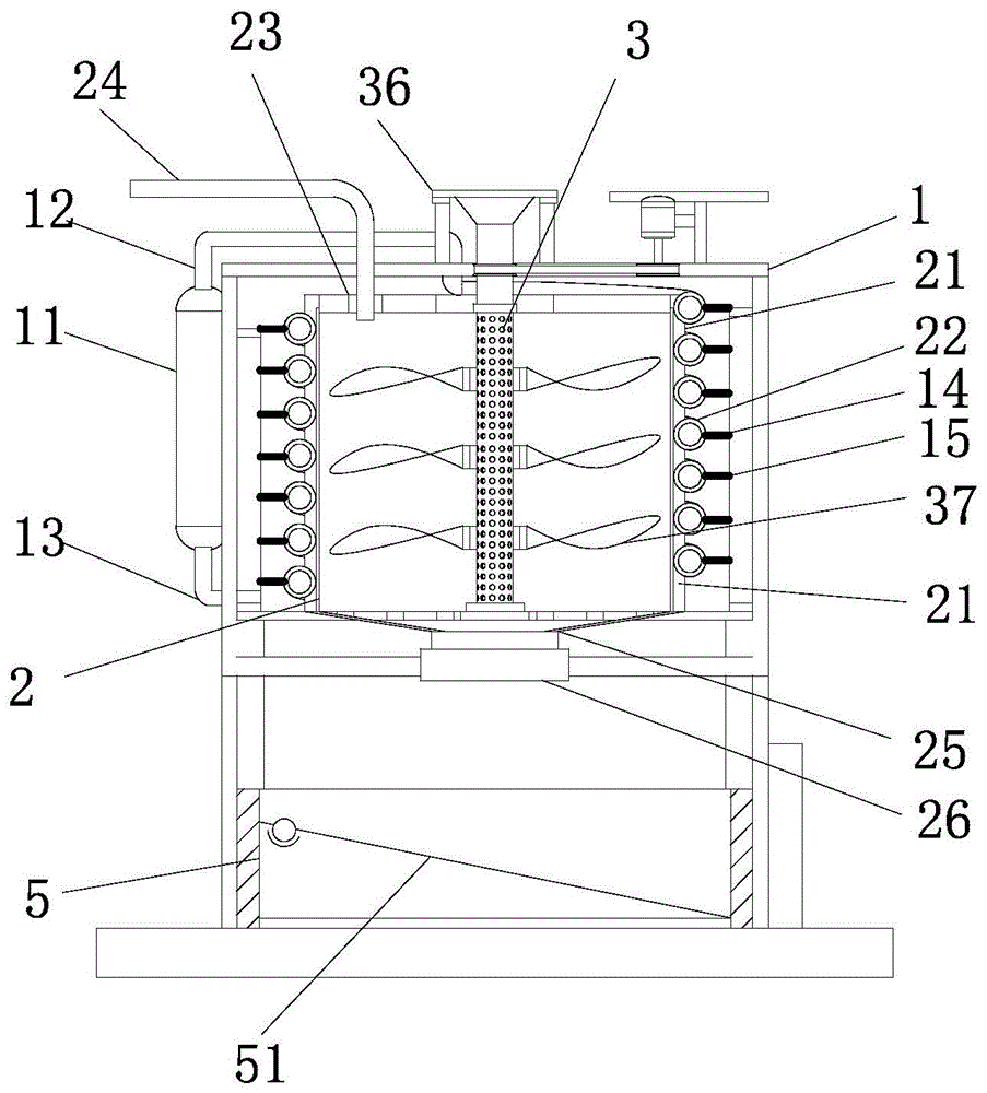
图1为本发明的结构示意图。Fig. 1 is a structural schematic diagram of the present invention.
图2为本发明的入料管道结构示意图。Fig. 2 is a schematic structural view of the feeding pipeline of the present invention.
图3为本发明中传动架的结构示意图。Fig. 3 is a structural schematic diagram of the transmission frame in the present invention.
图4为本发明中输料仓的结构示意图。Fig. 4 is a structural schematic diagram of the conveying bin in the present invention.
图中:1-外机架、11-加热源、12-回气管、13-输气管、14-外架板、15-横向支杆、2-内机箱、21-热调控层、22-热交换管道、23-气流孔、24-气压调控管、25-下料仓、26-下料管道、3-入料管道、31-入料斗、32-入料段、33-输料段、34-定位轴承、35-入料孔、37-搅拌叶、4-传动架、41-作业电机、42-驱动轮、43-从动轮、44-皮带、5-输料仓、51-刮料机构、52-导流板、53-侧边滑轨、54-辊轴、55-刮料辊、56-滑轮、57-排料架、58-轴承、59-螺杆、61-传动螺套、62-排料电机。In the figure: 1-outer frame, 11-heating source, 12-air return pipe, 13-air delivery pipe, 14-outer frame board, 15-horizontal strut, 2-inner chassis, 21-heat control layer, 22-heat Exchange pipe, 23-airflow hole, 24-air pressure control pipe, 25-feeding bin, 26-feeding pipe, 3-feeding pipe, 31-feeding hopper, 32-feeding section, 33-feeding section, 34 -locating bearing, 35-feed hole, 37-stirring blade, 4-transmission frame, 41-operating motor, 42-driving wheel, 43-driven wheel, 44-belt, 5-conveying bin, 51-scraping mechanism , 52-deflector, 53-side slide rail, 54-roller shaft, 55-scraping roller, 56-pulley, 57-discharging frame, 58-bearing, 59-screw, 61-drive screw sleeve, 62 -Discharging motor.
具体实施方式Detailed ways
下面将结合本发明实施例中的附图,对本发明实施例中的技术方案进行清楚、完整地描述,其示例表示在附图中。下面的描述涉及附图时,除非另有表示,不同附图中的相同数字表示相同或同种要素。The technical solutions in the embodiments of the present invention will be clearly and completely described below in conjunction with the accompanying drawings in the embodiments of the present invention, examples of which are shown in the accompanying drawings. When the following description refers to the accompanying drawings, the same numerals in different drawings refer to the same or like elements unless otherwise indicated.
显然,所描述的实施例仅仅是本发明一部分实施例,而不是全部的实施例。基于本发明中的实施例,本领域普通技术人员在没有做出创造性劳动前提下所获得的所有其他实施例,都属于本发明保护的范围。Apparently, the described embodiments are only some of the embodiments of the present invention, but not all of them. Based on the embodiments of the present invention, all other embodiments obtained by persons of ordinary skill in the art without making creative efforts belong to the protection scope of the present invention.
实施例一:Embodiment one:
请参阅图1,一种微生物土壤改良剂的发酵处理装置,包括外机架1和内机箱2,所述内机箱2设置在外机架1的内腔,所述内机箱2的侧壁上设置有热调控层21,所述热调控层21上设置有热交换管道22,所述热交换管道22呈螺旋式缠绕在内机箱2的外侧,所述热交换管道22嵌入至热调控层21内,所述外机架1的侧边设置有加热源11,所述加热源11的输气端设置在底部并且经输气管13与热交换管道22的进气端相连接,所述所述加热源11的入气端设置在底部并且经回气管12与热交换管道22的换气端相连接。所述外机架1上设置外架板14,所述外架板14上安装有若干道横向支杆15,所述热交换管道22架设在相应的横向支杆15上。Please refer to Fig. 1, a kind of fermentation treatment device of microbial soil improver, comprises
对于土壤改良剂的发酵处理,必然要严格控制发酵式的温度,现有技术往往都采用内置加热的方式,本申请则不同,本申请在内机箱2的外侧设置有热交换机构,采用由下往上的热空气输送方式,热交换管道22呈螺旋式缠绕在内机箱2的外侧,在热交换加热的同时保证内机箱2整体温度的全面性,从而提高土壤改良剂的发酵处理的效果。For the fermentation treatment of soil improver, it is necessary to strictly control the temperature of the fermentation type. The prior art often adopts the built-in heating method, but this application is different. The outside of the
所述内机箱2的顶板上设置气流孔23,所述气流孔23内安装有气压调控管24,所述气压调控管24外接气泵。同时本申请还在内机箱2顶板上设置有气流控制机构,对内机箱的内置气压进行有效的调控,配合上述温控装置,能够准确控制微生物土壤改良剂的制备环境。An
请参阅图1和图2、图3,内机箱2的内腔设置有入料管道3,所述入料管道3的顶部设置有入料斗31,所述入料管道3的分为入料段32和输料段33,所述输料段33上设置有若干道入料孔35,所述入料段32和输料段33之间设置有定位轴承34,所述入料管道3通过定位轴承34安装在内机箱2的顶板上,所述外机架1上安装有传动架4,所述传动架4上安装有作业电机41,所述作业电机41的驱动端安装有驱动轮42,所述入料段32上安装有从动轮43,所述从动轮43与驱动轮42之间通过皮带44相连接。所述入料管道3的外壁上等距安装有若干道搅拌叶37,所述搅拌叶37呈卷曲型流线体结构。Please refer to Fig. 1 and Fig. 2, Fig. 3, the inner cavity of
本申请将入料管道3与搅拌的中线轴设置为一体,在入料管道3直接沿着内机箱2的中线位置加入辅料,通过皮带传动机构带动入料管道3同步旋转,从而配合搅拌机构,使得加料更加均匀,提高微生物土壤改良剂的制备质量。In this application, the
实施例二:Embodiment two:
请参阅图1和图4,本实施例作为实施例一进一步的优化,在其基础上,所述内机箱2的底部设置有下料仓25,所述下料仓25呈倾斜向结构并且设置有下料管道26。所述外机架1的底端设置有输料仓5,所述输料仓5设置在下料管道26的正下方,下料管道26处设置有开合阀。Please refer to Fig. 1 and Fig. 4, this embodiment is further optimized as
所述输料仓5内安装有导流板52,所述导流板52的两侧设置有侧边滑轨53,所述导流板52上设置有刮料辊55,所述刮料辊55内置辊轴54,所述辊轴54的两端通过滑轮56嵌入安装在侧边滑轨53内。A deflector 52 is installed in the conveying
所述输料仓5的外壁上安装有排料架57,所述排料架57内通过轴承58安装有螺杆59,所述螺杆59上安装有传动螺套61,所述传动螺套61与辊轴54相连接,所述排料架57上安装有排料电机62,所述排料电机62安装在螺杆59的驱动端。A
一般来说,土壤改良剂发酵后往往为粘附性物质,为了保证土壤改良剂出料的顺畅性,本申请还设置有输料仓5,本申请在输料仓5内安装有刮料机构51,通过螺杆传动装置带动刮料辊55沿着侧边滑轨53滑动,从而带动物料的排出,有效避免出料的堵塞的问题,也减少物料的滞留量,方便后续器械的清洁。Generally speaking, the soil conditioner is often an adhesive substance after fermentation. In order to ensure the smoothness of the discharge of the soil conditioner, this application is also provided with a
对于本领域技术人员而言,显然本发明不限于上述示范性实施例的细节,而且在不背离本发明的精神或基本特征的情况下,能够以其他的具体形式实现本发明。因此,无论从哪一点来看,均应将实施例看作是示范性的,而且是非限制性的,本发明的范围由所附权利要求而不是上述说明限定,因此旨在将落在权利要求的等同要件的含义和范围内的所有变化囊括在本发明内。不应将权利要求中的任何附图标记视为限制所涉及的权利要求。It will be apparent to those skilled in the art that the invention is not limited to the details of the above-described exemplary embodiments, but that the invention can be embodied in other specific forms without departing from the spirit or essential characteristics of the invention. Accordingly, the embodiments should be regarded in all points of view as exemplary and not restrictive, the scope of the invention being defined by the appended claims rather than the foregoing description, and it is therefore intended that the scope of the invention be defined by the appended claims rather than by the foregoing description. All changes within the meaning and range of equivalents of the elements are embraced in the present invention. Any reference sign in a claim should not be construed as limiting the claim concerned.
此外,应当理解,虽然本说明书按照实施方式加以描述,但并非每个实施方式仅包含一个独立的技术方案,说明书的这种叙述方式仅仅是为清楚起见,本领域技术人员应当将说明书作为一个整体,各实施例中的技术方案也可以经适当组合,形成本领域技术人员可以理解的其他实施方式。In addition, it should be understood that although this specification is described according to implementation modes, not each implementation mode only includes an independent technical solution, and this description in the specification is only for clarity, and those skilled in the art should take the specification as a whole , the technical solutions in the various embodiments can also be properly combined to form other implementations that can be understood by those skilled in the art.
Claims (4)
Priority Applications (1)
| Application Number | Priority Date | Filing Date | Title |
|---|---|---|---|
| CN202010122863.1A CN111321069B (en) | 2020-02-27 | 2020-02-27 | A fermentation treatment device for microbial soil improver |
Applications Claiming Priority (1)
| Application Number | Priority Date | Filing Date | Title |
|---|---|---|---|
| CN202010122863.1A CN111321069B (en) | 2020-02-27 | 2020-02-27 | A fermentation treatment device for microbial soil improver |
Publications (2)
| Publication Number | Publication Date |
|---|---|
| CN111321069A CN111321069A (en) | 2020-06-23 |
| CN111321069B true CN111321069B (en) | 2023-06-09 |
Family
ID=71163408
Family Applications (1)
| Application Number | Title | Priority Date | Filing Date |
|---|---|---|---|
| CN202010122863.1A Active CN111321069B (en) | 2020-02-27 | 2020-02-27 | A fermentation treatment device for microbial soil improver |
Country Status (1)
| Country | Link |
|---|---|
| CN (1) | CN111321069B (en) |
Families Citing this family (1)
| Publication number | Priority date | Publication date | Assignee | Title |
|---|---|---|---|---|
| CN116716168B (en) * | 2023-06-14 | 2024-02-09 | 西安工程大学 | Stable microbial inoculum apparatus for producing |
Citations (9)
| Publication number | Priority date | Publication date | Assignee | Title |
|---|---|---|---|---|
| TWI604047B (en) * | 2016-05-03 | 2017-11-01 | zhao-guo Huang | Microbial enzyme fermentation device |
| CN207512089U (en) * | 2017-08-28 | 2018-06-19 | 云南润杰农业科技股份有限公司 | A kind of microbial manure installation for fermenting |
| CN207576670U (en) * | 2017-11-21 | 2018-07-06 | 河南易成新能源股份有限公司 | Air supporting graphite raw material collection device |
| CN208975635U (en) * | 2018-09-27 | 2019-06-14 | 山东天瀚新能源科技有限公司 | A kind of lithium ion battery slurrying mixing disk |
| CN209155618U (en) * | 2018-08-31 | 2019-07-26 | 泉州大众山涂料有限公司 | Mould wash mixer |
| CN110513972A (en) * | 2019-08-30 | 2019-11-29 | 韩雷 | A kind of gangue adobe drying equipment |
| CN209814817U (en) * | 2019-05-05 | 2019-12-20 | 启东市新联建筑材料有限公司 | Dry-mixed mortar storage tank |
| CN110624373A (en) * | 2019-09-28 | 2019-12-31 | 云和县宏峰模具厂 | A exhaust treatment device for adhesive sticker facial tissue production |
| CN210009879U (en) * | 2019-05-30 | 2020-02-04 | 深圳市润之鑫科技有限公司 | Mixing arrangement is used in AB glue production |
-
2020
- 2020-02-27 CN CN202010122863.1A patent/CN111321069B/en active Active
Patent Citations (9)
| Publication number | Priority date | Publication date | Assignee | Title |
|---|---|---|---|---|
| TWI604047B (en) * | 2016-05-03 | 2017-11-01 | zhao-guo Huang | Microbial enzyme fermentation device |
| CN207512089U (en) * | 2017-08-28 | 2018-06-19 | 云南润杰农业科技股份有限公司 | A kind of microbial manure installation for fermenting |
| CN207576670U (en) * | 2017-11-21 | 2018-07-06 | 河南易成新能源股份有限公司 | Air supporting graphite raw material collection device |
| CN209155618U (en) * | 2018-08-31 | 2019-07-26 | 泉州大众山涂料有限公司 | Mould wash mixer |
| CN208975635U (en) * | 2018-09-27 | 2019-06-14 | 山东天瀚新能源科技有限公司 | A kind of lithium ion battery slurrying mixing disk |
| CN209814817U (en) * | 2019-05-05 | 2019-12-20 | 启东市新联建筑材料有限公司 | Dry-mixed mortar storage tank |
| CN210009879U (en) * | 2019-05-30 | 2020-02-04 | 深圳市润之鑫科技有限公司 | Mixing arrangement is used in AB glue production |
| CN110513972A (en) * | 2019-08-30 | 2019-11-29 | 韩雷 | A kind of gangue adobe drying equipment |
| CN110624373A (en) * | 2019-09-28 | 2019-12-31 | 云和县宏峰模具厂 | A exhaust treatment device for adhesive sticker facial tissue production |
Non-Patent Citations (1)
| Title |
|---|
| 王楷 ; 张陇利 ; 许艇 ; 李季 ; .利用工业化好氧发酵工艺生产新型腐植酸土壤改良剂.腐植酸.2016,(第04期),全文. * |
Also Published As
| Publication number | Publication date |
|---|---|
| CN111321069A (en) | 2020-06-23 |
Similar Documents
| Publication | Publication Date | Title |
|---|---|---|
| CN111321069A (en) | Fermentation treatment device of microbial soil conditioner | |
| CN204544075U (en) | A kind of agitating device of adhesive | |
| CN205416272U (en) | Formula cooling device is forced to digital product casing injection molding difference | |
| CN219656445U (en) | Cooling cylinder for safe production of compound fertilizer | |
| CN111657374A (en) | Strip-shaped black tea oxygen fermentation device | |
| CN206334633U (en) | A kind of feed mixing and blending machine | |
| CN212979176U (en) | Extrusion production line | |
| CN212320294U (en) | A kind of hot air circulation drying equipment for pharmaceutical production | |
| CN211921578U (en) | A microbial culture device for reducing odor diffusion in livestock and poultry farms | |
| CN217777510U (en) | A quick cooling device for being directed at polymer rubber goods | |
| CN210934903U (en) | A device for efficiently producing nitrogen fertilizer synergist | |
| CN209798072U (en) | A TD treatment device for mold surface | |
| CN219567796U (en) | Tempering furnace for glass panel production | |
| CN221005676U (en) | Fertilizer production cooler | |
| CN209825072U (en) | Solid fermentation tank with accurate and controllable operating parameters | |
| CN221740261U (en) | A soybean fermentation tank | |
| CN221581956U (en) | Cooling bin for precoated sand production | |
| CN208952417U (en) | A kind of horizontal quality controling machine | |
| CN217729448U (en) | Nine-wheel double-layer sheet discharging machine | |
| CN201126320Y (en) | Double Suction Solid Material Rotary Cooler | |
| CN221968667U (en) | A water circulation cooling device for polyester pelletizing | |
| CN218710773U (en) | Galvanized steel pipe shaping cooling device | |
| CN117696848B (en) | A cooling device for copper strip | |
| CN114560606B (en) | Intermittent aeration assembly for fecal sewage treatment | |
| CN219525649U (en) | Tablet Conveyor for Powder Coating Production |
Legal Events
| Date | Code | Title | Description |
|---|---|---|---|
| PB01 | Publication | ||
| PB01 | Publication | ||
| SE01 | Entry into force of request for substantive examination | ||
| SE01 | Entry into force of request for substantive examination | ||
| GR01 | Patent grant | ||
| GR01 | Patent grant |