CN111315168A - Electrical cabinet capable of conveniently adjusting size of inner space - Google Patents
Electrical cabinet capable of conveniently adjusting size of inner space Download PDFInfo
- Publication number
- CN111315168A CN111315168A CN202010145404.5A CN202010145404A CN111315168A CN 111315168 A CN111315168 A CN 111315168A CN 202010145404 A CN202010145404 A CN 202010145404A CN 111315168 A CN111315168 A CN 111315168A
- Authority
- CN
- China
- Prior art keywords
- box body
- fixedly connected
- size
- outer box
- inner space
- Prior art date
- Legal status (The legal status is an assumption and is not a legal conclusion. Google has not performed a legal analysis and makes no representation as to the accuracy of the status listed.)
- Granted
Links
- 238000009434 installation Methods 0.000 claims abstract description 20
- 230000000903 blocking effect Effects 0.000 claims description 9
- 238000003825 pressing Methods 0.000 claims description 5
- 230000006978 adaptation Effects 0.000 claims description 3
- 239000011229 interlayer Substances 0.000 claims description 3
- 230000000694 effects Effects 0.000 description 5
- 238000000034 method Methods 0.000 description 4
- 230000008569 process Effects 0.000 description 4
- 230000003068 static effect Effects 0.000 description 3
- 230000009471 action Effects 0.000 description 2
- 230000004888 barrier function Effects 0.000 description 2
- 238000004891 communication Methods 0.000 description 2
- 238000006073 displacement reaction Methods 0.000 description 2
- 239000000463 material Substances 0.000 description 2
- 238000012986 modification Methods 0.000 description 2
- 230000004048 modification Effects 0.000 description 2
- 229910000831 Steel Inorganic materials 0.000 description 1
- 230000009286 beneficial effect Effects 0.000 description 1
- 230000009977 dual effect Effects 0.000 description 1
- 238000004146 energy storage Methods 0.000 description 1
- 230000007613 environmental effect Effects 0.000 description 1
- 238000004519 manufacturing process Methods 0.000 description 1
- 230000002035 prolonged effect Effects 0.000 description 1
- 239000010959 steel Substances 0.000 description 1
- 239000000126 substance Substances 0.000 description 1
- 239000002699 waste material Substances 0.000 description 1
- 238000003466 welding Methods 0.000 description 1
Images


Classifications
-
- H—ELECTRICITY
- H05—ELECTRIC TECHNIQUES NOT OTHERWISE PROVIDED FOR
- H05K—PRINTED CIRCUITS; CASINGS OR CONSTRUCTIONAL DETAILS OF ELECTRIC APPARATUS; MANUFACTURE OF ASSEMBLAGES OF ELECTRICAL COMPONENTS
- H05K5/00—Casings, cabinets or drawers for electric apparatus
- H05K5/02—Details
- H05K5/0217—Mechanical details of casings
-
- H—ELECTRICITY
- H05—ELECTRIC TECHNIQUES NOT OTHERWISE PROVIDED FOR
- H05K—PRINTED CIRCUITS; CASINGS OR CONSTRUCTIONAL DETAILS OF ELECTRIC APPARATUS; MANUFACTURE OF ASSEMBLAGES OF ELECTRICAL COMPONENTS
- H05K5/00—Casings, cabinets or drawers for electric apparatus
- H05K5/02—Details
- H05K5/0208—Interlock mechanisms; Means for avoiding unauthorised use or function, e.g. tamperproof
-
- H—ELECTRICITY
- H05—ELECTRIC TECHNIQUES NOT OTHERWISE PROVIDED FOR
- H05K—PRINTED CIRCUITS; CASINGS OR CONSTRUCTIONAL DETAILS OF ELECTRIC APPARATUS; MANUFACTURE OF ASSEMBLAGES OF ELECTRICAL COMPONENTS
- H05K7/00—Constructional details common to different types of electric apparatus
- H05K7/14—Mounting supporting structure in casing or on frame or rack
Landscapes
- Engineering & Computer Science (AREA)
- Microelectronics & Electronic Packaging (AREA)
- Computer Security & Cryptography (AREA)
- Patch Boards (AREA)
Abstract
The invention relates to the field of electric cabinets with adjustable space, and discloses an electric cabinet capable of conveniently adjusting the size of an internal space. This regulator cubicle that can conveniently adjust inner space size uses through the cooperation of interior box and installing port, possesses when the device extension back, and box and extension interior components and parts are connected in the space in accessible installing port will be interior, has avoided the inconvenient problem of installation that the space does not communicate and causes, has improved the device convenience.
Description
Technical Field
The invention relates to the field of electric cabinets with adjustable spaces, in particular to an electric cabinet capable of conveniently adjusting the size of an internal space.
Background
The electrical cabinet is a cabinet which is formed by processing steel and used for protecting components from working normally, is widely applied to various fields such as chemical industry, environmental protection, industry and the like, and is very important equipment in the field of energy storage.
Due to the materials and the manufacturing method, the internal space of the existing electrical cabinet is generally fixed, which results in that during the use process, when the requirements for the components in the electrical cabinet are changed and the components need to be additionally installed, the limited internal space can not meet the installation requirement of new components, and only can be replaced or the electrical cabinet is automatically modified, so that the use cost is greatly increased, in addition, the reinstallation and connection of the components will take a lot of time, waste manpower and material resources, and cause great economic loss, and a small part of the novel electrical cabinet has a certain function of expanding the internal space, but the expandable inner space is limited, and still cannot meet the actual demand, the practicability is low, and when the inner space is changed, the components and parts that have already been connected and accomplished cause the influence easily, and the space after some equipment expansion lacks the intercommunication with original space, causes the inconvenient condition of later stage installation.
For solving the problems, the electrical cabinet capable of conveniently adjusting the size of the internal space is provided, and has the advantages of large expansion space, adjustable expansion range, no influence on the connection of the internal connected structure and the communication of the expansion space and the original space.
Disclosure of Invention
In order to realize the purposes of large expansion space, adjustable expansion range and no influence on the communication between the connected structure inside and the expansion space and the original space, the invention provides the following technical scheme: an electrical cabinet capable of conveniently adjusting the size of an internal space, comprising: the inner box body, the outer box body, the moving groove, the blocking device, the mounting shaft, the adjusting ring, the rod sleeve, the gear seat, the check ring, the rotating ring, the reset spring, the pressing rod, the connecting plate, the connecting rod, the gear seat, the sliding block and the mounting opening.
The top of interior box is provided with the shifting chute, and the top of interior box and the below that is located the shifting chute are provided with stop device, and the preceding fixedly connected with installation axle of interior box installs adjustable ring, rod cover, pinion stand and retaining ring respectively in the outside of installation axle, and the internal rotation of adjustable ring is connected with the swivel becket, the preceding fixedly connected with reset spring of swivel becket, and reset spring passes through depression bar fixedly connected with connecting plate, the outside fixedly connected with connecting rod of rod cover, the incomplete gear of outside fixedly connected with of pinion stand.
Preferably, the blocking device comprises a triangular block, the lower part of the triangular block is fixedly connected with a supporting plate through a first spring, a second spring is installed below the supporting plate, the triangular block is fixedly connected with the second spring through a pressing rod, a through hole matched with the size of the pressing rod is formed in the supporting plate, the sliding block is static, the first spring and the second spring can effectively guarantee that the stiffness coefficient of the first spring and the stiffness coefficient of the second spring can play a certain blocking role on the sliding block, and when the triangular block is pressed down by the sliding block, the service life of the spring can be effectively prolonged through the combination of the double springs, and the use cost is reduced.
Preferably, the surface of the inner box body is provided with a groove matched with the outer box body, the depth of the groove meets the requirement that the outer box body can be positioned in the groove when the outer box body moves to the highest point and the lowest point, the outer box body can generate certain displacement in the vertical direction when moving, and the groove can ensure that the outer box body is always in close contact with the inner box body.
Preferably, the mounting shaft is fixedly mounted in front of the inner box and located in an interlayer between the inner box and the outer box, so that the mounting shaft and other structures connected thereto do not occupy the space in which the inner box and the outer box can be mounted, and the available space of the device is further enlarged.
Preferably, the rod sleeve is fixedly connected with the rotating ring through the connecting block, the connecting rod on the rod sleeve is movably hinged with the inner top of the outer box body, and the rotating ring can drive the connecting rod to rotate when rotating along with the gear seat and enable the outer box body to deviate through the connecting rod.
Preferably, the outer box body is two half box bodies which are symmetrically installed, the sliding blocks matched with the moving grooves are arranged at the inner tops of the two half box bodies, the installation shafts are symmetrical relative to the joint of the half box bodies, incomplete gears connected with gear seats on the installation shafts are meshed with each other, the outer box body can move in the horizontal direction along the moving grooves through the sliding blocks, the outer box body is prevented from inclining and deviating when moving, and meanwhile the two half box bodies can move synchronously due to meshing of the incomplete gears.
Preferably, the side walls of the inner box body are internally provided with mounting openings, so that the outer box body can be connected with components in the inner box body through the mounting openings after being expanded.
Advantageous effects
Compared with the prior art, the invention provides the electrical cabinet which can conveniently adjust the size of the internal space, and the electrical cabinet has the following beneficial effects:
1. this regulator cubicle that can conveniently adjust inner space size through blocking device's use, possesses the effect that hinders outer box removal, avoids it in transportation or installation, appears taking place the condition of skew when not needing the extension, has improved the stability of device.
2. This regulator cubicle that can conveniently adjust inner space size uses through the cooperation of interior box and outer box, possesses outer box from outside outwards to expand, does not influence the effect of interior box internals, and extension range is big, and the promotion that has reached inner space is great, and has avoided influencing connected element's purpose to a certain extent.
3. This regulator cubicle that can conveniently adjust inner space size uses through the cooperation of interior box and installing port, possesses when the device extension back, and box and extension interior components and parts are connected in the space in accessible installing port will be interior, has avoided the inconvenient problem of installation that the space does not communicate and causes, has improved the device convenience.
4. This regulator cubicle that can conveniently adjust inner space size uses through the cooperation of outer box, rod cover, gear seat, swivel becket, incomplete gear, connecting plate, reset spring and depression bar, possesses and inwards presses the gear seat, makes incomplete gear no longer meshed effect, has reached and can expand the device according to actual demand, the selectivity, makes the device application range wider, has improved the practicality of device.
Drawings
FIG. 1 is a schematic view of the internal structure of the present invention, with the device in an inoperative state;
FIG. 2 is a view of the device of the present invention in a partially deployed configuration, in which the device is in an operative configuration;
FIG. 3 is a side view of the mounting shaft and the attachment structure thereon of the present invention, with the device in an inoperative condition;
FIG. 4 is an enlarged view taken at A of FIG. 1, showing the apparatus in an inoperative condition according to the present invention;
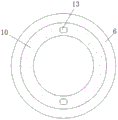
fig. 5 is a front view of the adjusting ring according to the invention, in a non-operating condition of the device.
The main reference numbers:
the device comprises an inner box body 1, an outer box body 2, a moving groove 3, a blocking device 4, a mounting shaft 5, an adjusting ring 6, a rod sleeve 7, a gear seat 8, a retainer ring 9, a rotating ring 10, a return spring 11, a pressure rod 12, a connecting plate 13, a connecting rod 14, a gear seat 15, a sliding block 16 and a mounting opening 17.
Detailed Description
In order to make the objects, technical solutions and advantages of the embodiments of the present disclosure more clear, the technical solutions in the embodiments of the present disclosure will be described clearly and completely with reference to the drawings in the embodiments of the present disclosure, and it is obvious that the described embodiments are only a part of the embodiments of the present disclosure, not all of the embodiments. All other embodiments, which can be derived by a person skilled in the art from the embodiments given herein without making any creative effort, shall fall within the protection scope of the present invention.
To maintain the following description of the embodiments of the present disclosure clear and concise, a detailed description of known functions and known components have been omitted from the present disclosure.
Referring to fig. 1-5, an electrical cabinet with an adjustable internal space is disclosed. It will be appreciated by those skilled in the art that other similar connections may be used to implement the present invention. Such as welding, bonding, or screwing.
In a further technical scheme provided by the invention, the electrical cabinet capable of conveniently adjusting the size of the internal space comprises an inner box body 1, an outer box body 2, a moving groove 3, a blocking device 4, a mounting shaft 5, an adjusting ring 6, a rod sleeve 7, a gear seat 8, a check ring 9, a rotating ring 10, a return spring 11, a pressure rod 12, a connecting plate 13, a connecting rod 14, a gear seat 15, a sliding block 16 and a mounting opening 17.
In the technical scheme further provided by the utility model, the surface of the inner box body 1 is provided with a groove matched with the outer box body 2, the depth of the groove is enough to ensure that the outer box body 2 is positioned in the groove when the outer box body 2 moves to the highest point and the lowest point, the outer box body 2 can generate certain displacement in the vertical direction when moving, the groove can ensure that the outer box body 2 is always in close contact with the inner box body, the top of the inner box body 1 is provided with a moving groove 3, the side wall of the inner box body 1 is internally provided with an installation opening 17, the outer box body 2 can be connected with components in the inner box body 1 through the installation opening 17 after being expanded, the top of the inner box body 1 is provided with a blocking device 4 positioned below the moving groove 3, the blocking device 4 comprises a triangular block, the lower part of the triangular block is fixedly connected with the supporting plate through a first spring, the lower part of the supporting plate is provided with a second spring, and the, be provided with the through-hole with depression bar size adaptation in the backup pad, slider 16 is when static, first spring and second spring can be effectual its coefficient of stiffness of assurance can play certain barrier action to the slider, and when 16 pushes down the triangle dog at the slider, the life that the combination of dual spring can effectual extension spring, use cost is reduced, the preceding fixedly connected with installation axle 5 of interior box 1, install adjustable ring 6 respectively in the outside of installation axle 5, rod cover 7, gear seat 8 and retaining ring 9, wherein, adjustable ring 6 and retaining ring 9 are fixed connection with the relation of being installed axle 5, rod cover 7 and gear seat 8 are swing joint with the relation of being connected 3 of installation axle 5.
The inner part of the adjusting ring 6 is rotatably connected with a rotating ring 10, the front of the rotating ring 10 is fixedly connected with a return spring 11, the return spring 11 is fixedly connected with a connecting plate 13 through a pressure rod 12, the outer side of the rod sleeve 7 is fixedly connected with a connecting rod 14, the rod sleeve 7 is fixedly connected with the rotating ring 10 through a connecting block, the connecting rod 14 on the rod sleeve 7 is movably hinged with the inner top part of the outer box body 2, the rotating ring 10 can drive the connecting rod 14 to rotate when rotating along with the gear seat 8, the outer box body 2 is deviated through the connecting rod 14, the outer side of the gear seat 8 is fixedly connected with an incomplete gear 15, the mounting shaft 5 is fixedly arranged in front of the inner box body 1 and is positioned in an interlayer between the inner box body 1 and the outer box body 2, the mounting shaft 5 and other structures connected with the mounting shaft do not occupy the mounting space of the inner box body and the outer box body, the usable space of, and the inner tops of the two half boxes are respectively provided with a sliding block 16 matched with the moving groove 3, the mounting shaft 5 is symmetrical about the joint of the half boxes, and the incomplete gears 15 connected with the gear seats 8 on the mounting shaft 5 are meshed with each other, so that the outer box 2 can move in the horizontal direction along the moving groove 3 through the sliding blocks 16, the outer box 2 is prevented from inclining and deviating when moving, and meanwhile, the two half boxes can synchronously move due to the meshing of the incomplete gears 15.
The working process and the principle of the device are as follows:
referring to fig. 1-5, when the device works, if the device needs to be lifted up, the gear seat 8 is rotated, because the gear seat 8 is fixedly connected with the incomplete gear 15, the incomplete gear 15 rotates, because the gear seat 8 is fixedly connected with the rotating ring 10 through the connecting plate 13, the pressure rod 12 and the return spring 11, the rotating ring 10 deflects and drives the rod sleeve 7 fixed with the rotating ring to deflect, the outer side of the rod sleeve 7 is fixedly connected with the connecting rod 14, and the connecting rod 14 is movably hinged with the outer box 2, so the connecting rod 14 drives the outer box 2 to deflect, at this time, the incomplete gear 15 is meshed with each other, so the two half boxes move in opposite directions and expand towards two sides, and under the action of the sliding block 16 and the moving groove 3, the outer box 2 is ensured not to deflect when moving, because the outer box 2 is positioned at the outer side of the inner box 1, the expanding space is larger, and the connected components in the inner box body 1 are not influenced, and the installation efficiency and the use convenience of the device are improved.
Referring to fig. 1-5, the device is at the during operation, when outer box 2 outwards expands, slider 16 and triangle dog contact, push down triangle dog, because the below of triangle dog is through first spring and backup pad fixed connection, the second spring is installed to the below of backup pad, and triangle dog passes through depression bar and second spring fixed connection, be provided with the through-hole with depression bar size adaptation in the backup pad, slider 16 is when static, first spring and second spring can be effectual guarantee its coefficient of stiffness can play certain barrier effect to the slider, and when slider 16 pushed down triangle dog, the life of extension spring that the combination of double spring can be effectual, use cost is reduced.
Referring to fig. 1-5, when the device works, if only the half box body on one side of the outer box body 2 needs to expand outwards, the gear seat 8 on one side in the device is pressed backwards, at this time, the gear seat 8 moves backwards, the gear seat 8 is fixedly connected with the pressure rod 12 through the connecting plate 13, and the pressure rod 12 is fixedly connected with the return spring 11, so that the return spring 11 is compressed, since the rotating ring 10 is installed inside the adjusting ring 6, and the adjusting ring 6 is fixedly connected with the mounting shaft 5, therefore, the position of the adjusting ring 6 is kept unchanged, the incomplete gear 15 fixedly connected to the gear seat 8 is staggered with the incomplete gear 15 on the other side and is not meshed any more, the gear seat 8 is rotated at the moment, the process in the working principle in the previous process is repeated, the partial expansion of the external box body 2 is completed, the purpose of adjusting the expansion range is achieved, the application range of the device is widened, and the practicability of the device is improved.
The above embodiments are merely exemplary embodiments of the present invention, which is not intended to limit the present invention, and the scope of the present invention is defined by the appended claims. Various modifications and equivalents may be made by those skilled in the art to the present invention without departing from the spirit and scope of the invention, and such modifications and equivalents should be considered to be within the scope of the invention.
Claims (7)
1. The utility model provides a can conveniently adjust regulator cubicle of inner space size, includes interior box (1) and outer box (2), its characterized in that: the top of interior box (1) is provided with shifting chute (3), the top of interior box (1) and the below that is located shifting chute (3) are provided with stop device (4), preceding fixedly connected with installation axle (5) of interior box (1), adjustable ring (6) are installed respectively in the outside of installation axle (5), rod cover (7), pinion stand (8) and retaining ring (9), the internal rotation of adjustable ring (6) is connected with swivel becket (10), preceding fixedly connected with reset spring (11) of swivel becket (10), reset spring (11) are through depression bar (12) fixedly connected with connecting plate (13), outside fixedly connected with connecting rod (14) of rod cover (7), the outside fixedly connected with incomplete gear (15) of pinion stand (8).
2. The electrical cabinet capable of conveniently adjusting the size of the inner space according to claim 1, wherein: the blocking device (4) comprises a triangular stop block, the lower part of the triangular stop block is fixedly connected with a supporting plate through a first spring, a second spring is installed below the supporting plate, the triangular stop block is fixedly connected with the second spring through a pressing rod, and a through hole matched with the pressing rod in size is formed in the supporting plate.
3. The electrical cabinet capable of conveniently adjusting the size of the inner space according to claim 1, wherein: the surface of the inner box body (1) is provided with a groove matched with the outer box body (2), and the depth of the groove can ensure that the outer box body (2) is positioned in the groove when the outer box body (2) moves to the highest point and the lowest point.
4. The electrical cabinet capable of conveniently adjusting the size of the inner space according to claim 1, wherein: the installation shaft (5) is fixedly installed in front of the inner box body (1) and is positioned in an interlayer between the inner box body (1) and the outer box body (2).
5. The electrical cabinet capable of conveniently adjusting the size of the inner space according to claim 1, wherein: the rod sleeve (7) is fixedly connected with the rotating ring (10) through a connecting block, and a connecting rod (14) on the rod sleeve (7) is movably hinged with the inner top of the outer box body (2).
6. The electrical cabinet capable of conveniently adjusting the size of the inner space according to claim 1, wherein: outer box (2) are two half boxes of symmetry installation, and the interior top of two half boxes all is provided with slider (16) with shifting chute (3) adaptation, and installation axle (5) are symmetrical about half box seam crossing, and install incomplete gear (15) intermeshing that gear seat (8) on axle (5) are connected.
7. The electrical cabinet capable of conveniently adjusting the size of the inner space according to claim 1, wherein: the side wall of the inner box body (1) is internally provided with mounting ports (17).
Priority Applications (1)
| Application Number | Priority Date | Filing Date | Title |
|---|---|---|---|
| CN202010145404.5A CN111315168B (en) | 2020-03-03 | 2020-03-03 | Electrical cabinet capable of conveniently adjusting size of inner space |
Applications Claiming Priority (1)
| Application Number | Priority Date | Filing Date | Title |
|---|---|---|---|
| CN202010145404.5A CN111315168B (en) | 2020-03-03 | 2020-03-03 | Electrical cabinet capable of conveniently adjusting size of inner space |
Publications (2)
| Publication Number | Publication Date |
|---|---|
| CN111315168A true CN111315168A (en) | 2020-06-19 |
| CN111315168B CN111315168B (en) | 2021-02-23 |
Family
ID=71147295
Family Applications (1)
| Application Number | Title | Priority Date | Filing Date |
|---|---|---|---|
| CN202010145404.5A Active CN111315168B (en) | 2020-03-03 | 2020-03-03 | Electrical cabinet capable of conveniently adjusting size of inner space |
Country Status (1)
| Country | Link |
|---|---|
| CN (1) | CN111315168B (en) |
Cited By (1)
| Publication number | Priority date | Publication date | Assignee | Title |
|---|---|---|---|---|
| CN112217101A (en) * | 2020-09-29 | 2021-01-12 | 江苏康盛电气集团有限责任公司 | Electric appliance cabinet with high expansibility |
Citations (4)
| Publication number | Priority date | Publication date | Assignee | Title |
|---|---|---|---|---|
| CN206107286U (en) * | 2016-09-20 | 2017-04-19 | 索凌电气有限公司 | Size adjustable regulator cubicle handcart |
| CN107120902A (en) * | 2017-05-26 | 2017-09-01 | 泰州库宝制冷设备制造有限公司 | Energy-conserving freezer of adjustable inner space size |
| CN207719633U (en) * | 2018-01-16 | 2018-08-10 | 广州市超盛医疗器械有限公司 | A kind of external hanging type rain-proof electrical cabinet |
| CN208241120U (en) * | 2018-04-16 | 2018-12-14 | 浙江正合安装有限公司 | A kind of distribution box of adjustable interior space size |
-
2020
- 2020-03-03 CN CN202010145404.5A patent/CN111315168B/en active Active
Patent Citations (4)
| Publication number | Priority date | Publication date | Assignee | Title |
|---|---|---|---|---|
| CN206107286U (en) * | 2016-09-20 | 2017-04-19 | 索凌电气有限公司 | Size adjustable regulator cubicle handcart |
| CN107120902A (en) * | 2017-05-26 | 2017-09-01 | 泰州库宝制冷设备制造有限公司 | Energy-conserving freezer of adjustable inner space size |
| CN207719633U (en) * | 2018-01-16 | 2018-08-10 | 广州市超盛医疗器械有限公司 | A kind of external hanging type rain-proof electrical cabinet |
| CN208241120U (en) * | 2018-04-16 | 2018-12-14 | 浙江正合安装有限公司 | A kind of distribution box of adjustable interior space size |
Cited By (1)
| Publication number | Priority date | Publication date | Assignee | Title |
|---|---|---|---|---|
| CN112217101A (en) * | 2020-09-29 | 2021-01-12 | 江苏康盛电气集团有限责任公司 | Electric appliance cabinet with high expansibility |
Also Published As
| Publication number | Publication date |
|---|---|
| CN111315168B (en) | 2021-02-23 |
Similar Documents
| Publication | Publication Date | Title |
|---|---|---|
| CN111315168B (en) | Electrical cabinet capable of conveniently adjusting size of inner space | |
| CN202265374U (en) | Simple vehicle-mounted lifting device | |
| CN210707656U (en) | Connecting rod mechanism of folding and expanding container | |
| CN219825279U (en) | Simple foundation pit protection template | |
| CN110107791B (en) | Arc-shaped mounting and fixing structure of LED display screen box body | |
| CN111392445A (en) | Rotary collecting and conveying device for stacked raw materials | |
| CN209741781U (en) | Multistage folding hydraulic pressure dam | |
| CN217177267U (en) | A spring shock absorber that is easy to install and fix based on electromechanical equipment | |
| CN214390576U (en) | Convenient assembled breaker and remove broken station of jaw | |
| CN210770975U (en) | Pipeline drainage device for road | |
| CN205164360U (en) | Filter mounting structure | |
| CN212685415U (en) | Folding rearview mirror bracket | |
| CN207092781U (en) | Hinge | |
| CN209338013U (en) | Driving device for ocean engineering crane | |
| CN216852757U (en) | Extensible wind-powered electricity generation intelligent control case | |
| CN204492581U (en) | A kind of ready-package safety protective door | |
| CN212637715U (en) | Multifunctional vehicle accessory posture adjusting working device | |
| CN220748182U (en) | Tap strutting arrangement of power catwalk | |
| CN220851806U (en) | Fire control pipeline infiltration detection device | |
| CN223133142U (en) | Electric gate for grain scraper | |
| CN223804066U (en) | A mounting structure and a pressurization trolley | |
| CN223115070U (en) | A sealing ring installation tool | |
| CN221395854U (en) | Turning device of box | |
| CN210218448U (en) | A convenient bearing seat fixing device | |
| CN218582283U (en) | Saggar valve with strong corrosion resistance |
Legal Events
| Date | Code | Title | Description |
|---|---|---|---|
| PB01 | Publication | ||
| PB01 | Publication | ||
| SE01 | Entry into force of request for substantive examination | ||
| SE01 | Entry into force of request for substantive examination | ||
| TA01 | Transfer of patent application right | ||
| TA01 | Transfer of patent application right |
Effective date of registration: 20210201 Address after: 414000 1st floor, building 4, Rongsheng electric power, Changjiang Avenue, Chenglingji new port area, Yueyang City, Hunan Province Applicant after: Hunan Rongsheng Longyuan Electric Technology Co.,Ltd. Address before: University of Electronic Science and Technology (Qingshuihe campus), no.2006 Xiyuan Avenue, high tech Zone, Chengdu, Sichuan 610000 Applicant before: Zhou Yuehua |
|
| GR01 | Patent grant | ||
| GR01 | Patent grant |