CN111271490A - Flushing valve - Google Patents
Flushing valve Download PDFInfo
- Publication number
- CN111271490A CN111271490A CN202010206386.7A CN202010206386A CN111271490A CN 111271490 A CN111271490 A CN 111271490A CN 202010206386 A CN202010206386 A CN 202010206386A CN 111271490 A CN111271490 A CN 111271490A
- Authority
- CN
- China
- Prior art keywords
- valve
- water
- flush
- water inlet
- section
- Prior art date
- Legal status (The legal status is an assumption and is not a legal conclusion. Google has not performed a legal analysis and makes no representation as to the accuracy of the status listed.)
- Granted
Links
- 238000011010 flushing procedure Methods 0.000 title claims abstract description 14
- XLYOFNOQVPJJNP-UHFFFAOYSA-N water Substances O XLYOFNOQVPJJNP-UHFFFAOYSA-N 0.000 claims abstract description 137
- 238000007789 sealing Methods 0.000 claims abstract description 40
- 238000013016 damping Methods 0.000 claims description 16
- 238000010586 diagram Methods 0.000 description 5
- 238000009434 installation Methods 0.000 description 5
- 208000035143 Bacterial infection Diseases 0.000 description 2
- 208000022362 bacterial infectious disease Diseases 0.000 description 2
- 238000006073 displacement reaction Methods 0.000 description 2
- 241000894006 Bacteria Species 0.000 description 1
- 239000012535 impurity Substances 0.000 description 1
- 238000000034 method Methods 0.000 description 1
Images


Classifications
-
- F—MECHANICAL ENGINEERING; LIGHTING; HEATING; WEAPONS; BLASTING
- F16—ENGINEERING ELEMENTS AND UNITS; GENERAL MEASURES FOR PRODUCING AND MAINTAINING EFFECTIVE FUNCTIONING OF MACHINES OR INSTALLATIONS; THERMAL INSULATION IN GENERAL
- F16K—VALVES; TAPS; COCKS; ACTUATING-FLOATS; DEVICES FOR VENTING OR AERATING
- F16K11/00—Multiple-way valves, e.g. mixing valves; Pipe fittings incorporating such valves
- F16K11/10—Multiple-way valves, e.g. mixing valves; Pipe fittings incorporating such valves with two or more closure members not moving as a unit
- F16K11/20—Multiple-way valves, e.g. mixing valves; Pipe fittings incorporating such valves with two or more closure members not moving as a unit operated by separate actuating members
- F16K11/22—Multiple-way valves, e.g. mixing valves; Pipe fittings incorporating such valves with two or more closure members not moving as a unit operated by separate actuating members with an actuating member for each valve, e.g. interconnected to form multiple-way valves
-
- B—PERFORMING OPERATIONS; TRANSPORTING
- B08—CLEANING
- B08B—CLEANING IN GENERAL; PREVENTION OF FOULING IN GENERAL
- B08B7/00—Cleaning by methods not provided for in a single other subclass or a single group in this subclass
-
- F—MECHANICAL ENGINEERING; LIGHTING; HEATING; WEAPONS; BLASTING
- F16—ENGINEERING ELEMENTS AND UNITS; GENERAL MEASURES FOR PRODUCING AND MAINTAINING EFFECTIVE FUNCTIONING OF MACHINES OR INSTALLATIONS; THERMAL INSULATION IN GENERAL
- F16K—VALVES; TAPS; COCKS; ACTUATING-FLOATS; DEVICES FOR VENTING OR AERATING
- F16K15/00—Check valves
-
- F—MECHANICAL ENGINEERING; LIGHTING; HEATING; WEAPONS; BLASTING
- F16—ENGINEERING ELEMENTS AND UNITS; GENERAL MEASURES FOR PRODUCING AND MAINTAINING EFFECTIVE FUNCTIONING OF MACHINES OR INSTALLATIONS; THERMAL INSULATION IN GENERAL
- F16K—VALVES; TAPS; COCKS; ACTUATING-FLOATS; DEVICES FOR VENTING OR AERATING
- F16K27/00—Construction of housing; Use of materials therefor
- F16K27/02—Construction of housing; Use of materials therefor of lift valves
- F16K27/0254—Construction of housing; Use of materials therefor of lift valves with conical shaped valve members
-
- F—MECHANICAL ENGINEERING; LIGHTING; HEATING; WEAPONS; BLASTING
- F16—ENGINEERING ELEMENTS AND UNITS; GENERAL MEASURES FOR PRODUCING AND MAINTAINING EFFECTIVE FUNCTIONING OF MACHINES OR INSTALLATIONS; THERMAL INSULATION IN GENERAL
- F16K—VALVES; TAPS; COCKS; ACTUATING-FLOATS; DEVICES FOR VENTING OR AERATING
- F16K31/00—Actuating devices; Operating means; Releasing devices
- F16K31/44—Mechanical actuating means
- F16K31/60—Handles
Landscapes
- Engineering & Computer Science (AREA)
- General Engineering & Computer Science (AREA)
- Mechanical Engineering (AREA)
- Self-Closing Valves And Venting Or Aerating Valves (AREA)
Abstract
Description
技术领域technical field
本发明涉及是一种冲洗阀的改进发明。The present invention relates to an improved invention of a flush valve.
背景技术Background technique
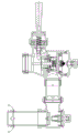
见附图1,传统冲洗阀是通过按压手杆驱动阀芯顶杆,使阀门开启,手杆则通过弹簧复位,若弹簧的弹力太小,手杆则不能复位,因此需要较大的力气去推动弹簧及阀芯顶杆;而且手杆需要与顶杆配合,因此冲洗阀的阀芯与按压开关的安装位置受到限制,两者需要靠近才能配合使用,这样不仅安装不方便,而且使用不便利。See Figure 1, the traditional flush valve is to drive the valve core by pressing the hand lever to open the valve, and the hand lever is reset by the spring. Push the spring and the valve core ejector rod; and the hand lever needs to cooperate with the ejector rod, so the installation position of the valve core of the flush valve and the push switch is limited, and the two need to be close to be used together, which is not only inconvenient to install, but also inconvenient to use .
发明内容SUMMARY OF THE INVENTION
鉴于背景技术中存在的技术问题,本发明所解决的技术问题旨在提供一种冲洗阀,不仅安装方便,而且使用便利。In view of the technical problems existing in the background art, the technical problem solved by the present invention aims to provide a flush valve, which is not only easy to install, but also easy to use.
为解决上述技术问题,本发明采用如下的技术方案:该种冲洗阀,包括有阀体、阀芯及冲洗开关,所述阀芯设置在阀体内,所述阀体的出水端连接排水管,所述阀芯顶部与阀体之间设有储水腔,所述阀芯底部与阀体的出水端配合,其特征在于所述冲洗开关包括有框体、阀杆以及与端盖,所述框体设有进水口和出水口,所述框体的内腔分为密封段和解封段,所述解封段比密封段的内径大,所述阀杆的顶端与端盖连接,所述阀杆的底端穿过密封段并进入解封段,所述阀杆的底端与密封段密封配合,所述内腔的密封段与框体的出水口接通,所述内腔的解封段与框体的进水口接通,所述进水口与通过进水管与储水腔连接,所述出水口通过出水管与阀体的排水管连接,所述阀杆外套设有弹簧,且弹簧设置在端盖与框体之间,所述框体与端盖之间具有按压空隙。In order to solve the above technical problems, the present invention adopts the following technical scheme: the flushing valve includes a valve body, a valve core and a flushing switch, the valve core is arranged in the valve body, and the water outlet end of the valve body is connected to a drain pipe, A water storage cavity is arranged between the top of the valve core and the valve body, and the bottom of the valve core is matched with the water outlet end of the valve body. It is characterized in that the flush switch includes a frame body, a valve stem and an end cover. The frame body is provided with a water inlet and a water outlet, the inner cavity of the frame body is divided into a sealing section and an unsealing section, the unsealing section is larger than the inner diameter of the sealing section, the top of the valve stem is connected with the end cover, the The bottom end of the valve rod passes through the sealing section and enters the unsealing section, the bottom end of the valve rod is in sealing fit with the sealing section, the sealing section of the inner cavity is connected with the water outlet of the frame, and the sealing section of the inner cavity is connected to the water outlet of the frame body. The sealing section is connected with the water inlet of the frame body, the water inlet is connected with the water storage cavity through the water inlet pipe, the water outlet is connected with the drain pipe of the valve body through the water outlet pipe, and the valve stem jacket is provided with a spring, and The spring is arranged between the end cover and the frame body, and there is a pressing gap between the frame body and the end cover.
所述冲洗开关设置有两组,分别为大水量开关和小水量开关,所述大水量开关的按压空隙比小水量开关的按压空隙大,所述进水管和出水管也设置有两组,分别为进水管一、出水管一、进水管二及出水管二。The flushing switch is provided with two groups, which are a large water volume switch and a small water volume switch. The pressing gap of the large water volume switch is larger than that of the small water volume switch. The water inlet pipe and the water outlet pipe are also provided with two groups, respectively. For the water inlet pipe 1, the water outlet pipe 1, the water inlet
所述阀芯包括有顶座、芯体、中座和底座,所述顶座设有与阀体的进水端相通的进水通道,所述进水通道与储水腔单向接通,所述顶座与阀体内壁密封配合,所述中座与阀体的出水端密封配合。The valve core includes a top seat, a core body, a middle seat and a base. The top seat is provided with a water inlet channel that communicates with the water inlet end of the valve body, and the water inlet channel is unidirectionally connected to the water storage cavity. The top seat is in sealing engagement with the inner wall of the valve body, and the middle seat is in sealing engagement with the water outlet end of the valve body.
所述顶座上设有延时座,所述延时座上开设有阻尼孔,所述阻尼孔与进水通道和储水腔接通。A delay seat is arranged on the top seat, and a damping hole is opened on the delay seat, and the damping hole is connected with the water inlet channel and the water storage cavity.
所述阻尼孔配设有弹簧通针,所述弹簧通针安装在延时座上。The damping hole is provided with a pogo pin, and the pogo pin is mounted on the delay seat.
本发明的冲洗开关与阀芯分开设置,两者不受距离限制,这样不仅便于阀体、阀芯及冲洗开关的安装,而且冲洗开关与阀芯、阀体的安装位置不受限制也更便于用户使用,而且冲洗开关远离阀芯、阀体,可以免受冲洗时细菌的感染,更加安全、卫生。The flush switch of the present invention is arranged separately from the valve core, and the distance between the two is not limited, which not only facilitates the installation of the valve body, the valve core and the flush switch, but also facilitates the installation of the flush switch, the valve core and the valve body without being restricted. It can be used by users, and the flush switch is far away from the valve core and valve body, which can avoid bacterial infection during flushing, and is safer and more hygienic.
附图说明Description of drawings
图1为传统冲洗阀的示意图。Figure 1 is a schematic diagram of a conventional flush valve.
图2为本发明的示意图。Figure 2 is a schematic diagram of the present invention.
图3为本发明阀体与阀芯的剖视图。3 is a cross-sectional view of the valve body and the valve core of the present invention.
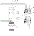
图4为本发明冲洗开关的剖视图。4 is a cross-sectional view of the flush switch of the present invention.
图5为本发明阀芯关闭状态示意图。FIG. 5 is a schematic diagram of the closed state of the valve core of the present invention.
图6为本发明阀芯开启状态示意图。FIG. 6 is a schematic diagram of the valve core of the present invention in an open state.
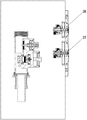
图7为本发明安装在墙体上的示意图。FIG. 7 is a schematic diagram of the present invention being installed on a wall.
具体实施方式Detailed ways
下面结合附图描述本发明的实施方式及实施例的有关细节及工作原理。该种冲洗阀,包括有阀体3、阀芯及冲洗开关5,所述阀芯设置在阀体3内,所述阀体的出水端连接排水管4,所述阀芯顶部与阀体之间设有储水腔11,所述阀芯底部与阀体的出水端配合,所述冲洗开关包括有框体16、阀杆20以及与端盖18,所述框体16设有进水口25和出水口21,所述框体的内腔分为密封段22和解封段23,所述解封段比密封段的内径大,内腔呈阶梯状,所述阀杆20的顶端与端盖18连接,所述阀杆的底端穿过密封段22并进入解封段23,所述阀杆的底端与密封段密封配合,阀杆20的底端外径比密封段22的内径大,阀杆的底端不会进入密封段并将密封段密封,使密封段与解封段分离;所述内腔的密封段22与框体的出水口21接通,所述内腔的解封段23与框体的进水口25接通,所述进水口25与通过进水管6与储水腔11连接,所述出水口21通过出水管1与阀体的排水管4连接,所述阀杆20外套设有弹簧19,且弹簧设置在端盖18与框体16之间,所述框体与端盖之间具有按压空隙17,按压端盖18,弹簧19受压,按压空隙17变小直至端盖18与框体16接触,此时,密封面打开,阀杆的底端深入解封段23,内腔的密封段与解封段相通,储水腔11、进水管6、阀体内腔、出水管1及排水管4相通,储水腔内的水通过进水管,经框体的内腔,再经过出水管,最后由阀体的排水管排出,随着储水腔内的水排空,阀芯沿阀体3内壁移动,阀体的出水端开启,并由排水管4排出,见附图6;而后,弹簧19推动端盖18复位,即阀杆20复位,水流被切断,出水管1停止排水,储水腔11内的水量增加推动阀芯复位,并将阀体的出水端关闭,见附图5,此时阀门关闭。本发明的冲洗开关通过进水管6和出水管1与阀体3连接,冲洗开关的安装位置不再受到限制,可以更大限度的扩大其安装范围,可以将冲洗开关5的位置远离阀体3,这样不仅便于安装,而且冲洗时细菌飞扬,这样可以免受细菌感染,使用也更安全、卫生;本发明只需轻轻按压端盖18克服弹簧19的弹力就可以将密封面打开,使将储水腔内的水排出,端盖重量轻,复位所需的弹力小,因此按压弹簧所需的力就小,更便于儿童及老年人使用。The relevant details and working principles of the embodiments and embodiments of the present invention will be described below with reference to the accompanying drawings. The flushing valve includes a
所述阀体3的内腔可以竖向设置或横向设置,若阀体的内腔竖向设置,则阀芯在阀体内上下移动,若阀体的内腔横向设置,则阀芯在阀体内左右移动,本实施例中,所述阀芯横向设置在阀体3内,所述阀芯包括有顶座8、芯体13、中座14和底座15,所述顶座8设有与阀体的进水端相通的进水通道12,所述进水通道与储水腔11单向接通,即进水通道内的水可以进入储水腔,所述储水腔内的水则不能进入进水通道,可以通过阻尼孔实现,阻尼孔一端与进水通道接通,阻尼孔的另一端与储水腔接通,本实施例中,所述顶座9上设有延时座,所述延时座上开设有阻尼孔,所述阻尼孔与进水通道和储水腔接通,通过阻尼孔实现进水通道内的水可以进入储水腔,所述储水腔内的水则不能进入进水通道;为避免阻尼孔堵塞,所述阻尼孔配设有弹簧通针10,所述弹簧通针安装在延时座9上,所述顶座8与阀体3内壁密封配合,所述中座14与阀体的出水端密封配合;排水时,阀芯向右移动,储水腔11内的水排出,直至弹簧通针与阀体接触,并且弹簧通针受压插入阻尼孔内,使阻尼孔通畅、不堵塞;当冲洗开关的阀杆20复位时,进水通道12的水通过阻尼孔进入储水腔11内,储水腔进水则推动阀芯向左移动并复位,阀芯重新将阀体的出水端关闭,若没有弹簧通针10,水中杂质可能会堵塞阻尼孔,导致阀芯不能复位,因此,弹簧通针的设置延长了冲洗阀的使用寿命。The inner cavity of the
所述冲洗开关设置有两组,分别为大水量开关27和小水量开关26,即需要大水量冲洗时,按压大水量开关,反之,则按压小水量开关;所述大水量开关的按压空隙比小水量开关的按压空隙大,所述进水管6和出水管1也设置有两组,分别为进水管一、出水管一、进水管二及出水管二,所述进水管一和进水管二均与储水腔接通,所述出水管一和出水管二则与排水管接通。所述阀杆20及端盖18的移动行程大则水量排出多,这是因为,阀杆20深入解封段23,密封面打开的空隙越大,那么出水量就越大,储水腔11内的水排出越多,阀芯移动的行程就长,复位所需的时间长,因此,排水量就大,反之则小,如此根据需求选择排水量,更加节能。The flushing switch is provided with two groups, which are a large
Claims (5)
Priority Applications (1)
| Application Number | Priority Date | Filing Date | Title |
|---|---|---|---|
| CN202010206386.7A CN111271490B (en) | 2020-03-23 | 2020-03-23 | A flush valve |
Applications Claiming Priority (1)
| Application Number | Priority Date | Filing Date | Title |
|---|---|---|---|
| CN202010206386.7A CN111271490B (en) | 2020-03-23 | 2020-03-23 | A flush valve |
Publications (2)
| Publication Number | Publication Date |
|---|---|
| CN111271490A true CN111271490A (en) | 2020-06-12 |
| CN111271490B CN111271490B (en) | 2025-03-07 |
Family
ID=70998422
Family Applications (1)
| Application Number | Title | Priority Date | Filing Date |
|---|---|---|---|
| CN202010206386.7A Active CN111271490B (en) | 2020-03-23 | 2020-03-23 | A flush valve |
Country Status (1)
| Country | Link |
|---|---|
| CN (1) | CN111271490B (en) |
Cited By (1)
| Publication number | Priority date | Publication date | Assignee | Title |
|---|---|---|---|---|
| CN112376660A (en) * | 2020-10-31 | 2021-02-19 | 浙江科欣实业有限公司 | Flushing valve |
Citations (6)
| Publication number | Priority date | Publication date | Assignee | Title |
|---|---|---|---|---|
| CN201110416Y (en) * | 2007-10-31 | 2008-09-03 | 温州帝威斯感应洁具有限公司 | Touch type block-resistant descaling time-delay self-closing water-saving device |
| CN101324286A (en) * | 2007-10-31 | 2008-12-17 | 温州帝威斯感应洁具有限公司 | Touch type block-resistant descaling time-delay self-closing water saving device |
| CN103669521A (en) * | 2013-12-25 | 2014-03-26 | 浙江科欣实业有限公司 | Automatic water pressure flushing valve |
| CN204878778U (en) * | 2015-08-24 | 2015-12-16 | 浙江科欣实业有限公司 | Controllable flushometer of economizing on water |
| CN206496012U (en) * | 2016-11-28 | 2017-09-15 | 浙江科欣实业有限公司 | One kind throttling flushing valve |
| CN211875181U (en) * | 2020-03-23 | 2020-11-06 | 浙江科欣实业有限公司 | a flush valve |
-
2020
- 2020-03-23 CN CN202010206386.7A patent/CN111271490B/en active Active
Patent Citations (6)
| Publication number | Priority date | Publication date | Assignee | Title |
|---|---|---|---|---|
| CN201110416Y (en) * | 2007-10-31 | 2008-09-03 | 温州帝威斯感应洁具有限公司 | Touch type block-resistant descaling time-delay self-closing water-saving device |
| CN101324286A (en) * | 2007-10-31 | 2008-12-17 | 温州帝威斯感应洁具有限公司 | Touch type block-resistant descaling time-delay self-closing water saving device |
| CN103669521A (en) * | 2013-12-25 | 2014-03-26 | 浙江科欣实业有限公司 | Automatic water pressure flushing valve |
| CN204878778U (en) * | 2015-08-24 | 2015-12-16 | 浙江科欣实业有限公司 | Controllable flushometer of economizing on water |
| CN206496012U (en) * | 2016-11-28 | 2017-09-15 | 浙江科欣实业有限公司 | One kind throttling flushing valve |
| CN211875181U (en) * | 2020-03-23 | 2020-11-06 | 浙江科欣实业有限公司 | a flush valve |
Cited By (1)
| Publication number | Priority date | Publication date | Assignee | Title |
|---|---|---|---|---|
| CN112376660A (en) * | 2020-10-31 | 2021-02-19 | 浙江科欣实业有限公司 | Flushing valve |
Also Published As
| Publication number | Publication date |
|---|---|
| CN111271490B (en) | 2025-03-07 |
Similar Documents
| Publication | Publication Date | Title |
|---|---|---|
| CN204852457U (en) | Double fluid volume auto -change over device | |
| CN102418374B (en) | Flushing device with pressure releasing function | |
| CN215367614U (en) | Pressure relief control valve, pressure water tank and toilet stool | |
| CN211875181U (en) | a flush valve | |
| CN103669521B (en) | Automatic water pressure flushing valve | |
| CN101324286A (en) | Touch type block-resistant descaling time-delay self-closing water saving device | |
| CN109356254B (en) | Self-flushing squatting pan | |
| CN214738518U (en) | Water inlet valve with anti-siphon structure and toilet bowl | |
| US9151028B2 (en) | Flushing valve | |
| CN213926551U (en) | Flushing valve | |
| CN111271490B (en) | A flush valve | |
| CN213836892U (en) | Flushing valve | |
| CN201151942Y (en) | Vacuum-discharging type water saving toilet | |
| CN210562475U (en) | An opening valve of a pressure flushing system and a toilet using the opening valve | |
| WO2023116887A1 (en) | Tankless mechanical valve flushing system | |
| CN218091131U (en) | A pre-flush system and toilet | |
| CN218233666U (en) | Anti-retention type washbasin deodorization drainage structure | |
| CN112376660B (en) | A flush valve | |
| CN215802046U (en) | Water inlet valve of toilet | |
| CN113700911B (en) | Double-waterway flushing valve capable of preventing siphon backflow | |
| CN216022675U (en) | Valve seat-free double-layer pipe straight-through type pressing sealing valve and anus cleaner after defecation | |
| CN217630315U (en) | Water outlet device of deodorizing urinal | |
| CN109252334A (en) | A kind of drainpipe and the washing machine using it | |
| CN214033941U (en) | Pressure type water tank touch-free response control structure | |
| CN210013300U (en) | Pre-stored water closestool |
Legal Events
| Date | Code | Title | Description |
|---|---|---|---|
| PB01 | Publication | ||
| PB01 | Publication | ||
| SE01 | Entry into force of request for substantive examination | ||
| SE01 | Entry into force of request for substantive examination | ||
| GR01 | Patent grant | ||
| GR01 | Patent grant |