CN111267257A - Follow-up dust collection assembly for stone processing machine - Google Patents
Follow-up dust collection assembly for stone processing machine Download PDFInfo
- Publication number
- CN111267257A CN111267257A CN202010257608.8A CN202010257608A CN111267257A CN 111267257 A CN111267257 A CN 111267257A CN 202010257608 A CN202010257608 A CN 202010257608A CN 111267257 A CN111267257 A CN 111267257A
- Authority
- CN
- China
- Prior art keywords
- dust
- dust collection
- plate
- horizontal convex
- convex plate
- Prior art date
- Legal status (The legal status is an assumption and is not a legal conclusion. Google has not performed a legal analysis and makes no representation as to the accuracy of the status listed.)
- Pending
Links
Images


Classifications
-
- B—PERFORMING OPERATIONS; TRANSPORTING
- B28—WORKING CEMENT, CLAY, OR STONE
- B28D—WORKING STONE OR STONE-LIKE MATERIALS
- B28D7/00—Accessories specially adapted for use with machines or devices of the preceding groups
- B28D7/02—Accessories specially adapted for use with machines or devices of the preceding groups for removing or laying dust, e.g. by spraying liquids; for cooling work
-
- B—PERFORMING OPERATIONS; TRANSPORTING
- B28—WORKING CEMENT, CLAY, OR STONE
- B28D—WORKING STONE OR STONE-LIKE MATERIALS
- B28D1/00—Working stone or stone-like materials, e.g. brick, concrete or glass, not provided for elsewhere; Machines, devices, tools therefor
- B28D1/22—Working stone or stone-like materials, e.g. brick, concrete or glass, not provided for elsewhere; Machines, devices, tools therefor by cutting, e.g. incising
- B28D1/24—Working stone or stone-like materials, e.g. brick, concrete or glass, not provided for elsewhere; Machines, devices, tools therefor by cutting, e.g. incising with cutting discs
Abstract
The invention relates to the technical field of water cups, in particular to a follow-up type dust collection assembly for a stone processing machine, which comprises a dust collection assembly body, wherein the dust collection assembly body comprises a first dust collection component and a second dust collection component; the first dust absorption component comprises a first horizontal convex plate and a second horizontal convex plate which are arranged on the left side and the right side of the bottom end surface of the blade housing; the front and back surfaces of the first horizontal convex plate and the second horizontal convex plate are flush with the front and back surfaces of the blade housing, and the front and back surfaces of the first horizontal convex plate and the second horizontal convex plate are respectively hinged with a front shielding plate and a back shielding plate; the dust collection device adopts a first dust collection component arranged on a cutting blade housing and a second dust collection component arranged on the bottom surface of a cutting plane, thereby realizing the combination of mobile dust collection and fixed dust collection; the dust collector has the advantages of convenient use and dust collection effect, reduces the pollution of dust to the workshop environment, and also ensures the health of operators.
Description
[ technical field ] A method for producing a semiconductor device
The invention relates to the technical field of water cups, in particular to a follow-up dust collection assembly for a stone processing machine.
[ background of the invention ]
Stone machines are machines and tools required in the technological processes of stone mining, machining, finishing and the like. The stone cutting machine is a multi-cutter multi-stage stone cutting machine consisting of a cutter group, a stone conveying table, a positioning guide plate and a frame. The cutting knife groups are arranged on the upper part of the stone conveying table and are arranged on the frame, and positioning guide plates are fixed among the cutting knife groups; the cutting knife group consists of a motor, a belt, a knife wheel shaft and a cutting knife, and the cutting knife is fixed on the knife wheel shaft. When the traditional stone cutting machine is used, the following problems exist: when the stone cutting machine is used for cutting stone, a large amount of dust can be generated, and the large amount of dust can pollute the environment and bring harm to the health of operators.
[ summary of the invention ]
The invention aims to provide a follow-up dust collection assembly for a stone processing machine, aiming at the defects and shortcomings of the prior art.
The invention relates to a follow-up dust collection component for a stone processing machine, which comprises a dust collection component body, a dust collection component body and a dust collection component, wherein the dust collection component body comprises a first dust collection component and a second dust collection component;
the first dust absorption component comprises a first horizontal convex plate and a second horizontal convex plate which are arranged on the left side and the right side of the bottom end surface of the blade housing; the front and back surfaces of the first horizontal convex plate and the second horizontal convex plate are flush with the front and back surfaces of the blade housing, and the front and back surfaces of the first horizontal convex plate and the second horizontal convex plate are respectively hinged with a front shielding plate and a back shielding plate; the front shielding plate and the rear shielding plate are rectangular, and oblique springs I are arranged between the left side and the right side of the top end of the inner wall of the front shielding plate and the two front ends of the horizontal convex plate I and the horizontal convex plate II; a second inclined spring is arranged between the left side and the right side of the top end of the inner wall of the rear shielding plate and the two front ends of the first horizontal convex plate and the second horizontal convex plate; a first elastic cloth and a second elastic cloth are arranged between the left side and the right side of the front shielding plate and the rear shielding plate; the first horizontal convex plate and the second horizontal convex plate are respectively provided with a first circular dust suction hole and a second circular dust suction hole; the first horn-shaped dust hood and the second horn-shaped dust hood are respectively arranged on the first circular dust absorption hole and the second circular dust absorption hole; the first horn-shaped dust hood and the second horn-shaped dust hood are connected with a first suction fan and a second suction fan through a first dust suction hose and a second dust suction hose, and the first suction fan and the second suction fan are arranged on the upper parts of the inner side surfaces of a first dust storage box and a second dust storage box on vertical columns in the middle of the left support and the right support; the left bracket and the right bracket are correspondingly arranged on the left side and the right side of the top surface of the cutting table board;
the second dust collection component comprises a reversed frustum-shaped dust collection barrel arranged on the bottom surface of the cutting table; the top surface of the inverted frustum-shaped dust collecting barrel is open, a third through hole is formed in the bottom surface of the inverted frustum-shaped dust collecting barrel, and a third suction fan is mounted on the third through hole; the lower parts of the left side and the right side of the inverted frustum-shaped dust collecting barrel are correspondingly provided with a sewage discharge pipe; a plurality of dust suction holes which are arranged in rows and columns are formed in the opening of the cutting table surface, which is opposite to the top surface of the inverted frustum-shaped dust collecting barrel, and the dust suction holes are communicated with the inverted frustum-shaped dust collecting barrel; the upper part of the left side of the inverted-pyramid-shaped dust collecting barrel is provided with a spray nozzle, the spray nozzle is connected with a horizontal water pipe, and the horizontal water pipe is connected with a water pump in a water tank; the water tank is arranged on the upper part of the outer side surface of the first support side plate on the left side of the bottom surface of the cutting table top; a second supporting side plate corresponding to the first supporting side plate is arranged on the right side of the bottom surface of the cutting table top; and a wastewater collection bin is arranged between the bottoms of the inner side surfaces of the first supporting side plate and the second supporting side plate, and the top surface of the wastewater collection bin is in an open shape and faces the drain pipes on the left side and the right side of the reversed frustum-shaped dust collection barrel.
Furthermore, the front shielding plate and the rear shielding plate are made of transparent plastic materials.
Further, a dihedral angle formed between the front shutter and the front of the blade housing is a, 45 < a <75 °.
Further, a dihedral angle a is formed between the rear shutter and the rear of the blade housing, 45 < a <75 °.
Furthermore, the bottom ends of the first elastic cloth and the second elastic cloth are provided with a plurality of brush heads.
Furthermore, a ball valve is arranged on a pipe orifice at the bottom end of the sewage draining pipe.
After adopting the structure, the invention has the beneficial effects that: the invention relates to a follow-up dust collection component for a stone processing machine, which adopts a first dust collection component arranged on a cutting blade housing and a second dust collection component arranged on the bottom surface of a cutting plane, thereby realizing the combination of movable dust collection and fixed dust collection; the dust collector has the advantages of convenient use and dust collection effect, reduces the pollution of dust to the workshop environment, and also ensures the health of operators.
[ description of the drawings ]
The accompanying drawings, which are included to provide a further understanding of the invention and are incorporated in and constitute a part of this application, and are not to be considered limiting of the invention, in which:
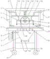
FIG. 1 is a front view of the present invention mounted on a cutting machine;
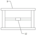
FIG. 2 is a schematic view of the structure of the left bracket of the present invention
FIG. 3 is a schematic view of the construction of the top mount of the present invention;
fig. 4 is a partial schematic side view of a first dust suction member according to the present invention.
Description of reference numerals:
1. supporting the first side plate; 2. a dust collecting barrel in a shape of a chamfered frustum; 3. a water tank; 4. a water pump; 5. cutting the table top; 6. a telescopic cylinder; 7. a first horn-shaped dust hood; 8. a first suction fan; 9. a top support; 10. a first dust collection hose; 11. a square horizontal bar; 12. a square sleeve; 13. a vertical spring barrel; 14. a blade housing; 15. a second dust collection hose; 16. a second suction fan; 17. a second dust storage box; 18. a second horizontal convex plate; 19. a front shield; 20. a brush head; 21. the stone to be cut; 22. a sewage draining outlet; 23. a third suction fan; 24. a blow-off pipe; 25. a guide wheel; 26. an infrared lamp cap; 27. a dust collection hole; 28. pressing a plate; 29. a first inclined spring; 30. a rear shield; 31. a second oblique spring; 32. a left bracket; 33. the elastic cloth is one.
[ detailed description ] embodiments
In order to make the objects, technical solutions and advantages of the embodiments of the present invention clearer, the technical solutions in the embodiments of the present invention will be clearly and completely described below with reference to the drawings in the embodiments of the present invention, and it is obvious that the described embodiments are some, but not all, embodiments of the present invention. All other embodiments, which can be derived by a person skilled in the art from the embodiments given herein without making any creative effort, shall fall within the protection scope of the present invention.
In the description of the present invention, it should be noted that the terms "center", "upper", "lower", "left", "right", "vertical", "horizontal", "inner", "outer", etc., indicate orientations or positional relationships based on the orientations or positional relationships shown in the drawings, and are only for convenience of description and simplicity of description, but do not indicate or imply that the device or element being referred to must have a particular orientation, be constructed and operated in a particular orientation, and thus, should not be construed as limiting the present invention.
As shown in fig. 1 to 4, the follow-up type dust collection assembly for a stone processing machine according to the present embodiment comprises a dust collection assembly body, wherein the dust collection assembly body comprises a first dust collection component and a second dust collection component;
the first dust absorption component comprises a first horizontal convex plate and a second horizontal convex plate 18 which are arranged on the left side and the right side of the bottom end surface of the blade housing; the first horizontal convex plate and the second horizontal convex plate 18 are rectangular, the front and back surfaces of the first horizontal convex plate and the second horizontal convex plate 18 are flush with the front and back surfaces of the blade housing 14, and the front and back surfaces of the first horizontal convex plate and the second horizontal convex plate 18 are respectively hinged with a front shielding plate 19 and a back shielding plate 30; the front shielding plate 19 and the rear shielding plate 30 are rectangular, and oblique springs I29 are arranged between the left side and the right side of the top end of the inner wall of the front shielding plate 19 and the front two ends of the horizontal convex plate I and the horizontal convex plate II; a second inclined spring 31 is arranged between the left side and the right side of the top end of the inner wall of the rear shielding plate 30 and the two front ends of the first horizontal convex plate and the second horizontal convex plate; a first elastic cloth 33 and a second elastic cloth are arranged between the left side and the right side of the front shielding plate 19 and the rear shielding plate 30; the first horizontal convex plate 18 and the second horizontal convex plate 18 are respectively provided with a first circular dust suction hole and a second circular dust suction hole; the first horn-shaped dust hood 7 and the second horn-shaped dust hood are respectively arranged on the first circular dust absorption hole and the second circular dust absorption hole; the first horn-shaped dust hood 7 and the second horn-shaped dust hood are connected with a first suction fan 8 and a second suction fan 16 through a first dust suction hose 10 and a second dust suction hose 15, and the first suction fan 8 and the second suction fan 16 are arranged on the upper parts of the inner side surfaces of a first dust storage box and a second dust storage box 17 on vertical columns in the middle of a left support 32 and a right support; the left bracket 32 and the right bracket are correspondingly arranged on the left side and the right side of the top surface of the cutting table top 5;
the second dust suction component comprises a reversed frustum-shaped dust collecting barrel 2 arranged on the bottom surface of the cutting table top 5; the top surface of the inverted frustum-shaped dust collecting barrel 2 is open, a third through hole is formed in the bottom surface of the inverted frustum-shaped dust collecting barrel 2, and a third suction fan 23 is mounted on the third through hole; the lower parts of the left side and the right side of the inverted frustum-shaped dust collecting barrel 2 are correspondingly provided with a sewage discharge pipe 24; a plurality of dust suction holes 27 arranged in rows and columns are formed in the cutting table surface 5 opposite to the opening on the top surface of the inverted frustum-shaped dust collecting barrel 2, and the dust suction holes 27 are communicated with the inverted frustum-shaped dust collecting barrel 2; a spray nozzle is arranged at the upper part of the left side of the inverted frustum-shaped dust collecting barrel 2 and is connected with a horizontal water pipe, and the horizontal water pipe is connected with a water pump 4 in a water tank 3; the water tank 3 is arranged on the upper part of the outer side surface of the first support side plate 1 on the left side of the bottom surface of the cutting table top 5; a second supporting side plate corresponding to the first supporting side plate 1 is arranged on the right side of the bottom surface of the cutting table top 5; a waste water collecting bin is arranged between the bottoms of the inner side surfaces of the first supporting side plate 1 and the second supporting side plate, the top surface of the waste water collecting bin is in an open shape and faces the drain pipes 24 on the left side and the right side of the reversed frustum-shaped dust collecting barrel 2.
Further, the front shield 19 and the rear shield 30 are made of transparent plastic.
Further, the dihedral angle formed between the front shutter 19 and the front of the blade housing 14 is a, 45 < a <75 °.
Further, the dihedral angle formed between the rear shutter 30 and the rear of the blade housing 14 is a, 45 < a < 75.
Further, the bottom ends of the first elastic cloth 33 and the second elastic cloth are respectively provided with a plurality of brush heads 20.
Further, a ball valve is arranged on a bottom end pipe orifice of the sewage draining pipe 24.
The working principle of the invention is as follows:
in the design, the stone cutting machine comprises a cutting table top 5, wherein a first supporting side plate 1 and a second supporting side plate are correspondingly arranged on the left side and the right side of the bottom surface of the cutting table top 5, and guide wheels 25 are respectively arranged at the front end and the rear end of the bottom end of the first supporting side plate 1 and the bottom end of the second supporting side plate; a waste water collecting bin is arranged at the lower part between the first supporting side plate 1 and the second supporting side plate; the left bracket 32 and the right bracket are correspondingly arranged on the left side and the right side of the top surface of the cutting table top 5; the top ends of the left bracket 32 and the right bracket are provided with top brackets 9; a horizontal cross beam is arranged in the middle of the top support, the cross section of the horizontal cross beam is square, a square sleeve 12 is mounted on the horizontal cross beam, a vertical spring barrel 13 is welded on the bottom surface of the square sleeve 12, a square vertical rod is arranged at the bottom end of the vertical spring barrel 13, square holes penetrating through the square vertical rod are formed in the left side and the right side of the square vertical rod, a square horizontal rod 11 is inserted in the square holes in a penetrating manner, and T-shaped raised heads are arranged at the left end and the right end of the square horizontal rod;
the bottom end of the square vertical rod is welded with a blade housing 14, and the blade housing 14 is in a semicircular shape; the blade housing 14 is composed of a semi-circular front housing piece and a semi-circular rear housing piece, and a semi-circular arc cover plate is welded on the top of the semi-circular front housing piece and the semi-circular rear housing piece to form a semi-circular blade housing with an opening at the bottom end; the middle parts of the bottom ends of the semicircular front shell piece and the semicircular rear shell piece are provided with central semicircular convex plates which protrude downwards, and a bearing is arranged between the two central semicircular convex plates;
a cutting blade is arranged in the blade housing 14, the cutting blade is arranged on a rotating shaft, the rotating shaft is arranged between two bearings in the middle of the bottom end of the inner wall of the blade housing 14, a shaft head on one side of the rotating shaft is connected with the output end of a motor, and the motor is arranged on the middle of the bottom surface of one back of the blade housing 14 to form a cutting head;
the middle parts of the left support 32 and the right support are respectively provided with a vertical column, the upper parts of the outer side surfaces of the two vertical columns are respectively provided with a first dust storage box and a second dust storage box 17, and the upper parts of the inner sides of the first dust storage box and the second dust storage box 17 are respectively provided with a first suction fan 8 and a second suction fan 16. T-shaped guide rails are arranged on the inner side surfaces of the vertical columns in the middle of the left support 32 and the right support, and T-shaped raised heads at the left end and the right end of the square horizontal rod 11 are respectively clamped on the T-shaped guide rails;
in the design, the U-shaped handles are correspondingly arranged on the upper parts of the front and the back of the blade housing 14, so that an operator can conveniently hold the U-shaped handles and can conveniently pull down the cutting head, the square vertical rod of the cutting head drives the square horizontal rod 11 to synchronously move downwards on the T-shaped guide rail, and the square horizontal rod 11 ensures the balance of downward movement of the cutting head, so that downward movement is realized; when not in use, the vertical spring barrel 13 is convenient to retract and move upwards due to the elasticity of the vertical spring barrel.
In this design, the square montant of cutting head is through its quad slit, conveniently removes about square horizon bar 11 formation forms, and square sleeve 12 also removes along the horizontal direction on horizontal beam in step simultaneously to realize horizontal migration.
When the stone cutting table is used in the design, the stone 21 to be cut is placed on the cutting table surface 5; then four telescopic cylinders 6 arranged at the lower parts of the inner side surfaces of the left bracket 32 and the right bracket are controlled to work, and piston rods of the four telescopic cylinders 6 drive the pressing plates 28 to be respectively pressed on the periphery of the surface of the stone 21 to be cut so as to form the fixation of the stone 21 to be cut; two infrared lamp heads 26 are installed at the left and right sides of the bottom surface of the opening blade cover 14, and the vertical plane formed by the two infrared lamp heads 26 and the cutting blade of the cutting head are on the same vertical plane, so that the cutting position of the stone material 21 to be cut can be conveniently adjusted.
Holding U-shaped handles on the front and back surfaces of the cutting head, moving downwards, starting cutting when cutting multiple pieces of stone 21 to be cut in contact with the cutting head, synchronously moving downwards a front shielding plate 19 and a rear shielding plate 30 on a first dust absorption component arranged on the cutting head, and forming a movable synchronous linkage dust absorption bin when the front shielding plate 19, the rear shielding plate 30, a first elastic cloth 33 and a second elastic cloth on two sides reach the cutting table top 5; the front shielding plate 19 and the rear shielding plate 30 are made of transparent plastic materials, so that the initial cutting positions of the cutting tool and the stone 21 to be cut can be conveniently observed; a large amount of dust is generated at the beginning of cutting; and at the moment, the first suction fan 8 and the second suction fan 16 are controlled, the first suction fan 8 and the second suction fan 16 absorb a large amount of dust generated by cutting through the first dust absorption hose 10 and the second dust absorption hose by utilizing the first horn-shaped dust absorption cover 7 and the second horn-shaped dust absorption cover to the first dust storage box and the second dust storage box 17.
In the design, when the cutting head is used for cutting the stone 21 to be cut, the cutting head moves downwards along with the deepening of cutting processing, and at the moment, a first inclined spring 29 is arranged between the left side and the right side of the top end of the inner wall of the front shielding plate 19 and the two front ends of the first horizontal convex plate and the second horizontal convex plate; a second inclined spring 31 is arranged between the left side and the right side of the top end of the inner wall of the rear shielding plate 30 and the two front ends of the first horizontal convex plate and the second horizontal convex plate; a first elastic cloth 33 and a second elastic cloth are arranged between the left side and the right side of the front shielding plate 19 and the rear shielding plate 30; therefore, the front shielding plate 19 and the rear shielding plate 30 can move towards the outside direction, the elastic cloth I33 and the elastic cloth II are pulled towards the two sides direction due to the elasticity, and the movable synchronous linkage dust suction bin is still covered at the cutting position for cutting the stone 21 to be cut, so that the dust suction effect can be ensured.
And meanwhile, the second dust suction component is controlled to synchronously work, the third suction fan 23 is controlled to work, a plurality of dust suction holes 27 in the cutting table surface 5 are utilized to synchronously absorb dust generated during cutting into the inverted frustum-shaped dust collecting barrel 2, the water pump 4 is controlled to simultaneously feed water and spray atomized water by utilizing a spray nozzle, the mixed dust forms sewage, the sewage is placed in the inverted frustum-shaped dust collecting barrel 2, suction force generated by the first suction fan and the second suction fan cannot be formed, and dust is sucked out from the dust suction holes 27 in a reverse mode. When the dust and sewage in the inverted frustum-shaped dust collecting barrel 2 is more, the ball valve on the bottom pipe orifice of the sewage discharge pipe 24 is opened, the sewage is conveniently guided to the waste water collecting bin, and the right side of the bottom surface of the waste water collecting bin is provided with the sewage discharge port 22, so that the post treatment is facilitated.
In this design, the bottom of the elastic cloth 33 and the elastic cloth 20 are provided with a plurality of brush heads, so that dust on a cutting plane can be conveniently cleaned when the dust collecting device moves, and the dust on the cutting plane is cleaned to the dust collecting hole 27 and then to the dust collecting barrel 2 in the shape of a chamfered table.
The invention relates to a follow-up dust collection component for a stone processing machine, which adopts a first dust collection component arranged on a cutting blade housing and a second dust collection component arranged on the bottom surface of a cutting plane, thereby realizing the combination of movable dust collection and fixed dust collection; the dust collector has the advantages of convenient use and dust collection effect, reduces the pollution of dust to the workshop environment, and also ensures the health of operators.
The above examples are only intended to illustrate the technical solution of the present invention, but not to limit it; although the present invention has been described in detail with reference to the foregoing embodiments, it will be understood by those of ordinary skill in the art that: the technical solutions described in the foregoing embodiments may still be modified, or some technical features may be equivalently replaced; and such modifications or substitutions do not depart from the spirit and scope of the corresponding technical solutions of the embodiments of the present invention.
Claims (6)
1. A follow-up dust collection component for a stone processing machine comprises a dust collection component body, wherein the dust collection component body comprises a first dust collection component and a second dust collection component;
the first dust absorption component comprises a first horizontal convex plate and a second horizontal convex plate which are arranged on the left side and the right side of the bottom end surface of the blade housing; the front and back surfaces of the first horizontal convex plate and the second horizontal convex plate are flush with the front and back surfaces of the blade housing, and the front and back surfaces of the first horizontal convex plate and the second horizontal convex plate are respectively hinged with a front shielding plate and a back shielding plate; the front shielding plate and the rear shielding plate are rectangular, and oblique springs I are arranged between the left side and the right side of the top end of the inner wall of the front shielding plate and the two front ends of the horizontal convex plate I and the horizontal convex plate II; a second inclined spring is arranged between the left side and the right side of the top end of the inner wall of the rear shielding plate and the two front ends of the first horizontal convex plate and the second horizontal convex plate; a first elastic cloth and a second elastic cloth are arranged between the left side and the right side of the front shielding plate and the rear shielding plate; the first horizontal convex plate and the second horizontal convex plate are respectively provided with a first circular dust suction hole and a second circular dust suction hole; the first horn-shaped dust hood and the second horn-shaped dust hood are respectively arranged on the first circular dust absorption hole and the second circular dust absorption hole; the first horn-shaped dust hood and the second horn-shaped dust hood are connected with a first suction fan and a second suction fan through a first dust suction hose and a second dust suction hose, and the first suction fan and the second suction fan are arranged on the upper parts of the inner side surfaces of a first dust storage box and a second dust storage box on vertical columns in the middle of the left support and the right support; the left bracket and the right bracket are correspondingly arranged on the left side and the right side of the top surface of the cutting table board;
the second dust collection component comprises a reversed frustum-shaped dust collection barrel arranged on the bottom surface of the cutting table; the top surface of the inverted frustum-shaped dust collecting barrel is open, a third through hole is formed in the bottom surface of the inverted frustum-shaped dust collecting barrel, and a third suction fan is mounted on the third through hole; the lower parts of the left side and the right side of the inverted frustum-shaped dust collecting barrel are correspondingly provided with a sewage discharge pipe; a plurality of dust suction holes which are arranged in rows and columns are formed in the opening of the cutting table surface, which is opposite to the top surface of the inverted frustum-shaped dust collecting barrel, and the dust suction holes are communicated with the inverted frustum-shaped dust collecting barrel; the upper part of the left side of the inverted-pyramid-shaped dust collecting barrel is provided with a spray nozzle, the spray nozzle is connected with a horizontal water pipe, and the horizontal water pipe is connected with a water pump in a water tank; the water tank is arranged on the upper part of the outer side surface of the first support side plate on the left side of the bottom surface of the cutting table top; a second supporting side plate corresponding to the first supporting side plate is arranged on the right side of the bottom surface of the cutting table top; and a wastewater collection bin is arranged between the bottoms of the inner side surfaces of the first supporting side plate and the second supporting side plate, and the top surface of the wastewater collection bin is in an open shape and faces the drain pipes on the left side and the right side of the reversed frustum-shaped dust collection barrel.
2. The follow-up type dust collection assembly for the stone processing machine as claimed in claim 1, wherein: the front shielding plate and the rear shielding plate are made of transparent plastic materials.
3. The follow-up type dust collection assembly for the stone processing machine as claimed in claim 1, wherein: the dihedral angle formed between the front shutter and the front of the blade housing is a, 45 < a < 75.
4. The follow-up type dust collection assembly for the stone processing machine as claimed in claim 1, wherein: the dihedral angle formed between the rear shutter and the rear of the blade housing is a, 45 < a < 75.
5. The follow-up type dust collection assembly for the stone processing machine as claimed in claim 1, wherein: the bottom ends of the elastic cloth I and the elastic cloth II are provided with a plurality of brush heads.
6. The follow-up type dust collection assembly for the stone processing machine as claimed in claim 1, wherein: and a ball valve is arranged on the bottom end pipe orifice of the sewage discharge pipe.
Priority Applications (1)
| Application Number | Priority Date | Filing Date | Title |
|---|---|---|---|
| CN202010257608.8A CN111267257A (en) | 2020-04-03 | 2020-04-03 | Follow-up dust collection assembly for stone processing machine |
Applications Claiming Priority (1)
| Application Number | Priority Date | Filing Date | Title |
|---|---|---|---|
| CN202010257608.8A CN111267257A (en) | 2020-04-03 | 2020-04-03 | Follow-up dust collection assembly for stone processing machine |
Publications (1)
| Publication Number | Publication Date |
|---|---|
| CN111267257A true CN111267257A (en) | 2020-06-12 |
Family
ID=70992120
Family Applications (1)
| Application Number | Title | Priority Date | Filing Date |
|---|---|---|---|
| CN202010257608.8A Pending CN111267257A (en) | 2020-04-03 | 2020-04-03 | Follow-up dust collection assembly for stone processing machine |
Country Status (1)
| Country | Link |
|---|---|
| CN (1) | CN111267257A (en) |
Cited By (2)
| Publication number | Priority date | Publication date | Assignee | Title |
|---|---|---|---|---|
| CN112157826A (en) * | 2020-09-18 | 2021-01-01 | 江苏聚优新型建材有限公司 | Novel stone brick processing device |
| CN114558958A (en) * | 2022-02-24 | 2022-05-31 | 杭州良淋电子科技股份有限公司 | Cutting equipment for automobile wire harness production |
-
2020
- 2020-04-03 CN CN202010257608.8A patent/CN111267257A/en active Pending
Cited By (2)
| Publication number | Priority date | Publication date | Assignee | Title |
|---|---|---|---|---|
| CN112157826A (en) * | 2020-09-18 | 2021-01-01 | 江苏聚优新型建材有限公司 | Novel stone brick processing device |
| CN114558958A (en) * | 2022-02-24 | 2022-05-31 | 杭州良淋电子科技股份有限公司 | Cutting equipment for automobile wire harness production |
Similar Documents
| Publication | Publication Date | Title |
|---|---|---|
| CN210435403U (en) | Bench drilling machine with cleaning mechanism | |
| CN110712061A (en) | Metal debris collecting device for milling head part machined by milling machine | |
| CN111267257A (en) | Follow-up dust collection assembly for stone processing machine | |
| CN208811690U (en) | A kind of carving and milling machine concentration chip removal device | |
| CN212288219U (en) | Follow-up dust collection assembly for stone processing machine | |
| CN208215031U (en) | Bell housing cross grinding processing unit (plant) | |
| CN216574593U (en) | Automatic waste collecting device of open type fixed press | |
| CN215788499U (en) | Metal product machining device convenient for recycling waste chips | |
| CN213135465U (en) | Laser cutting machine convenient to remove | |
| CN112139830B (en) | Flexible double-workbench exchange equipment for numerical control machine tool | |
| CN210997755U (en) | Numerical control planer type milling machine workstation chip removal device | |
| CN209303775U (en) | A kind of milling machine for collecting processing waste material | |
| CN219402499U (en) | Five-axis precise numerical control planer type milling machine | |
| CN108772635B (en) | Full-automatic laser cutting production workstation | |
| CN218983319U (en) | Grooving device with dust suppression structure | |
| CN216326911U (en) | Four-process double-station double-material-pushing cutting machine | |
| CN218694381U (en) | High numerical control cutting device that steel pipe layer frame was used | |
| CN216504182U (en) | Multi-station grinding machine | |
| CN220681089U (en) | Float forming machine | |
| CN220006510U (en) | Electric welding equipment for hydraulic and electromechanical production | |
| CN217512887U (en) | Radial drilling machine | |
| CN217371696U (en) | Full-automatic zinc-aluminum alloy edging equipment | |
| CN216576618U (en) | Vertical machining center support | |
| CN215619177U (en) | Integral type bridge type stonecutter | |
| CN213970220U (en) | High-speed gantry mill |
Legal Events
| Date | Code | Title | Description |
|---|---|---|---|
| PB01 | Publication | ||
| PB01 | Publication | ||
| SE01 | Entry into force of request for substantive examination | ||
| SE01 | Entry into force of request for substantive examination |