CN111251481A - Straight and curved screen cutting machine - Google Patents
Straight and curved screen cutting machine Download PDFInfo
- Publication number
- CN111251481A CN111251481A CN202010294323.1A CN202010294323A CN111251481A CN 111251481 A CN111251481 A CN 111251481A CN 202010294323 A CN202010294323 A CN 202010294323A CN 111251481 A CN111251481 A CN 111251481A
- Authority
- CN
- China
- Prior art keywords
- guide rail
- slider
- fixedly installed
- plate
- cutting machine
- Prior art date
- Legal status (The legal status is an assumption and is not a legal conclusion. Google has not performed a legal analysis and makes no representation as to the accuracy of the status listed.)
- Granted
Links
Images


Classifications
-
- B—PERFORMING OPERATIONS; TRANSPORTING
- B28—WORKING CEMENT, CLAY, OR STONE
- B28D—WORKING STONE OR STONE-LIKE MATERIALS
- B28D1/00—Working stone or stone-like materials, e.g. brick, concrete or glass, not provided for elsewhere; Machines, devices, tools therefor
- B28D1/22—Working stone or stone-like materials, e.g. brick, concrete or glass, not provided for elsewhere; Machines, devices, tools therefor by cutting, e.g. incising
- B28D1/24—Working stone or stone-like materials, e.g. brick, concrete or glass, not provided for elsewhere; Machines, devices, tools therefor by cutting, e.g. incising with cutting discs
-
- B—PERFORMING OPERATIONS; TRANSPORTING
- B28—WORKING CEMENT, CLAY, OR STONE
- B28D—WORKING STONE OR STONE-LIKE MATERIALS
- B28D7/00—Accessories specially adapted for use with machines or devices of the preceding groups
-
- B—PERFORMING OPERATIONS; TRANSPORTING
- B28—WORKING CEMENT, CLAY, OR STONE
- B28D—WORKING STONE OR STONE-LIKE MATERIALS
- B28D7/00—Accessories specially adapted for use with machines or devices of the preceding groups
- B28D7/04—Accessories specially adapted for use with machines or devices of the preceding groups for supporting or holding work or conveying or discharging work
Landscapes
- Engineering & Computer Science (AREA)
- Mechanical Engineering (AREA)
- Mining & Mineral Resources (AREA)
- Processing Of Stones Or Stones Resemblance Materials (AREA)
Abstract
Description
技术领域technical field
本发明保护一种切割机,特别是一种直面、曲面屏幕切割机,属于手机维修设备技术领域。The invention protects a cutting machine, in particular a straight-faced and curved screen cutting machine, and belongs to the technical field of mobile phone repair equipment.
背景技术Background technique
随着手机、平板电脑等电子产品的发展,其在人们生活中的应用也越来越广泛。目前,手机、平板电脑等的屏占比越来越大,甚至出现全面屏等产品,而此种电子产品在使用过程中,容易因为挤压、不慎掉落或其他原因,造成屏幕保护玻璃损坏,就需要对其进行更换或维修,手机屏幕的盖板与中框之间用胶水固定的,售后维修时,为了需要拆开屏幕和盖板,屏幕保护玻璃在拆卸时往往采用加热后采用工具撬的拆卸方式,容易损坏液晶屏。为了解决此问题,人们发明了屏幕切割机,在拆卸屏幕保护玻璃时,通过屏幕切割机对屏幕保护玻璃进行切割,方便其拆除。With the development of electronic products such as mobile phones and tablet computers, their applications in people's lives are becoming more and more extensive. At present, the screen ratio of mobile phones, tablet computers, etc. is getting larger and larger, and even products such as full screens appear. During the use of such electronic products, it is easy to cause screen protection glass due to extrusion, accidental dropping or other reasons. If it is damaged, it needs to be replaced or repaired. The cover plate and the middle frame of the mobile phone screen are fixed with glue. During after-sales maintenance, in order to disassemble the screen and the cover plate, the screen protection glass is often heated and used for disassembly. The disassembly method of the tool pry is easy to damage the LCD screen. In order to solve this problem, a screen cutting machine is invented. When removing the screen protective glass, the screen protective glass is cut by the screen cutting machine to facilitate its removal.
现有技术的屏幕切割机的平面工作平台是固定在底板上的,斜面工作平台是可旋转调节其倾斜角度,当其水平放置时,可用于切割直面屏幕(或称为平面屏幕),当其倾斜设置时,可用于切割曲面屏幕。斜面工作平台可旋转调节角度的目的,在切割直面屏时,可调节成平面,与平面工作平台相连,成为一体平台,斜面工作平台设置在平面工作平台的右边,因平面工作平台是固定的,造成切割曲屏时,操作空间太小,不好操作。The flat working platform of the prior art screen cutting machine is fixed on the bottom plate, and the inclined working platform can be rotated to adjust its inclination angle. When it is placed horizontally, it can be used to cut a straight screen (or a flat screen). Can be used to cut curved screens when tilted. The purpose of the inclined working platform can be rotated to adjust the angle. When cutting the straight screen, it can be adjusted into a plane, which is connected with the plane working platform to become an integrated platform. The inclined working platform is set on the right side of the plane working platform. Because the plane working platform is fixed, When cutting the curved screen, the operation space is too small and it is difficult to operate.
切割头的左、右和上、下滑动采用镀铬棒和直线轴承进行定位和限位,造成切割头左右、上下摆动误差可达到1-2毫米,切割精准度极差,非常容易切毁屏幕。The left, right and up and down sliding of the cutting head are positioned and limited by chrome-plated rods and linear bearings, resulting in the left and right and up and down swinging errors of the cutting head reaching 1-2 mm, the cutting accuracy is extremely poor, and it is very easy to cut the screen.
发明内容SUMMARY OF THE INVENTION
针对上述提到的现有技术中的屏幕切割机操作繁锁,切割误差大,容易切毁屏幕的问题,本发明提供一种新的直面、曲面屏幕切割机,其采用导轨和滑块设置的滑动工作平台和可调式斜面工作台,切割头的前后左右和上下滑动均采用导轨和滑块结构进行限位,操作简单、切割精准。Aiming at the above-mentioned problems of the screen cutting machine in the prior art, the operation is complicated, the cutting error is large, and the screen is easy to be cut. Sliding working platform and adjustable inclined working platform, the front, back, left and right and up and down sliding of the cutting head are limited by the guide rail and slider structure, which is easy to operate and accurate in cutting.
本发明解决其技术问题采用的技术方案是:一种直面、曲面屏幕切割机,切割机包括底板、平面工作台、斜面工作台、水平调节机构、竖直调节结构、电机和切割片,平面工作台直接或间接通过第一导轨滑块副安装在底板上,斜面工作台安装在底板上,水平调节机构通过第二导轨滑块副安装在底板上,斜面工作台设置在平面工作台和水平调节机构之间,竖直调节结构通过第三导轨滑块副安装在水平调节机构上,电机直接或间接安装在电机安装板上,电机安装板直接或间接通过第四导轨滑块副安装在竖直调节结构上,切割片安装在电机的主轴上。The technical scheme adopted by the present invention to solve the technical problem is: a straight-faced, curved screen cutting machine, the cutting machine includes a base plate, a flat worktable, an inclined worktable, a horizontal adjustment mechanism, a vertical adjustment structure, a motor and a cutting blade, and the plane works The table is directly or indirectly installed on the base plate through the first guide rail slider pair, the inclined table is installed on the base plate, the horizontal adjustment mechanism is installed on the base plate through the second guide rail slider pair, and the inclined surface table is installed on the flat work table and horizontal adjustment mechanism. Between the mechanisms, the vertical adjustment structure is installed on the horizontal adjustment mechanism through the third guide rail slider pair, the motor is directly or indirectly installed on the motor mounting plate, and the motor mounting plate is directly or indirectly installed on the vertical adjustment mechanism through the fourth guide rail slider pair. In the adjustment structure, the cutting blade is installed on the main shaft of the motor.
本发明解决其技术问题采用的技术方案进一步还包括:The technical scheme adopted by the present invention to solve the technical problem further includes:
所述的底板上固定安装有平面工作台支撑座,平面工作台支撑座上方固定安装有第一导轨,第一导轨上安装有第一滑块,第一滑块与平面工作台固定安装在一起,或者平面工作台支撑座上方固定安装有第一滑块,第一导轨安装在第一滑块上,第一导轨与平面工作台固定安装在一起。A flat worktable support seat is fixedly installed on the bottom plate, a first guide rail is fixedly installed above the flat worktable support seat, a first sliding block is installed on the first guide rail, and the first sliding block and the flat worktable are fixedly installed together , or a first sliding block is fixedly installed above the support base of the flat worktable, the first guide rail is installed on the first sliding block, and the first guide rail and the flat worktable are fixedly installed together.
所述的第一导轨两端头处侧边分别固定安装有一个第一限位螺钉。A first limit screw is fixedly installed on the side edges of the two ends of the first guide rail respectively.
所述的平面工作台支撑座上对应于第一导轨两端头处分别固定安装有固定磁铁。Fixed magnets are respectively fixedly installed on the support base of the plane worktable corresponding to both ends of the first guide rail.
所述的斜面工作台通过销轴安装在第一支撑板和第二支撑板之间,第一支撑板和第二支撑板分别固定安装在底板上,第一支撑板上开设有条形孔,斜面工作台侧面安装有锁紧螺丝。The inclined workbench is installed between the first support plate and the second support plate through the pin shaft, the first support plate and the second support plate are respectively fixed on the bottom plate, and the first support plate is provided with a strip hole, There are locking screws installed on the side of the inclined table.
所述的斜面工作台底部位置处固定安装有第三定位条,斜面工作台一端固定安装有第四定位条。A third positioning strip is fixedly installed at the bottom of the inclined worktable, and a fourth positioning strip is fixedly installed at one end of the inclined worktable.
所述的第二导轨滑块副包括第二导轨和第二滑块,第二滑块设置在第二导轨上,第二导轨一端端头处或两端头处侧边分别固定安装有一个第二限位螺钉。The second guide rail slider pair includes a second guide rail and a second slider, the second slider is arranged on the second guide rail, and a first guide rail is fixedly installed at one end of the second guide rail or at the side edges of both ends. Two limit screws.
所述的第二滑块上固定安装有第一固定支架,第一固定支架横截面呈“凹”字形,其底部支撑板与第二滑块固定安装在一起,两侧板分别固定安装在底部支撑板上。The second sliding block is fixedly installed with a first fixing bracket, the cross section of the first fixing bracket is in a "concave" shape, the bottom support plate is fixedly installed with the second sliding block, and the two side plates are respectively fixed and installed at the bottom support plate.
所述的第三导轨滑块副包括第三导轨和第三滑块,第三滑块安装在第三导轨上,第三滑块上固定安装有第二固定支架,第二固定支架横截面呈竖直的“凹”字形,其底部支撑板竖直设置,两侧板水平设置,分别固定安装在底部支撑板上,下方的侧板固定安装在第三滑块上,第二固定支架下方的侧板上,开设有第一导向孔,第一固定支架两侧板间固定安装有第一导向柱,第一导向柱插装在第一导向孔内,第一导向柱上套装有第一复位弹簧,第一固定支架侧板上安装有第一千分尺,第一千分尺与第一固定支架安装在一起。The third guide rail slider pair includes a third guide rail and a third slider, the third slider is installed on the third guide rail, and a second fixing bracket is fixedly installed on the third slider, and the second fixing bracket has a cross-section. The vertical "concave" shape, the bottom support plate is vertically arranged, the two side plates are arranged horizontally, and are fixedly installed on the bottom support plate respectively, the lower side plate is fixedly installed on the third slider, and the lower side plate is fixed on the second fixed bracket. The side plate is provided with a first guide hole, a first guide column is fixedly installed between the two side plates of the first fixing bracket, the first guide column is inserted into the first guide hole, and the first guide column is sleeved with a first reset A spring, a first micrometer is installed on the side plate of the first fixing bracket, and the first micrometer is installed together with the first fixing bracket.
所述的第四导轨滑块副包括第四导轨和第四滑块,第四滑块安装在第四导轨上,第四滑块上固定安装有电机滑动板,电机滑动板上开设有第二导向孔,第二固定支架两侧板间固定安装有第二导向柱,第二导向柱插装在第二导向孔内,第二导向柱上套装有第二复位弹簧,第二固定支架的上侧板上安装有第二千分尺,第二千分尺与电机滑动板相对设置在一起。The fourth guide rail slider pair includes a fourth guide rail and a fourth slider, the fourth slider is mounted on the fourth guide rail, a motor sliding plate is fixedly installed on the fourth slider, and a second sliding plate is provided on the motor sliding plate. A guide hole, a second guide column is fixedly installed between the two side plates of the second fixing bracket, the second guide column is inserted into the second guide hole, a second return spring is sleeved on the second guide column, and the upper part of the second fixing bracket is A second micrometer is installed on the side plate, and the second micrometer is arranged opposite to the motor sliding plate.
本发明的有益效果是:本发明是用于切割屏幕盖板和手机中框之间的缝隙,达到容易拆屏的目的。本发明采用导轨和滑块设置的滑动工作平台和可调式斜面工作台,切割头的前后左右和上下滑动均采用导轨和滑块结构进行限位,操作简单、切割精准。The beneficial effects of the present invention are as follows: the present invention is used for cutting the gap between the screen cover and the middle frame of the mobile phone, so as to achieve the purpose of easily disassembling the screen. The invention adopts the sliding working platform and the adjustable inclined working platform set by the guide rail and the slider, the front, back, left, right and up and down sliding of the cutting head are limited by the guide rail and the slider structure, and the operation is simple and the cutting is accurate.
下面将结合附图和具体实施方式对本发明做进一步说明。The present invention will be further described below with reference to the accompanying drawings and specific embodiments.
附图说明Description of drawings
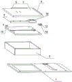
图1为本发明立体结构示意图。FIG. 1 is a schematic diagram of the three-dimensional structure of the present invention.
图2为本发明分解状态结构示意图。FIG. 2 is a schematic diagram of the structure of the present invention in a disassembled state.
图3为本发明直面屏幕切割部分分解状态结构示意图。FIG. 3 is a schematic structural diagram of the disassembled state of the cutting part of the straight-face screen according to the present invention.
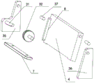
图4为本发明曲面屏幕切割部分分解状态结构示意图。FIG. 4 is a schematic diagram of the structure in an exploded state of the cutting part of the curved screen according to the present invention.
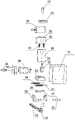
图5为本发明切割头部分分解状态结构示意图。FIG. 5 is a schematic structural diagram of the cutting head of the present invention in a partially disassembled state.
图中,1-底板,2-平面工作台支撑座,3-平面工作台,4-斜面工作台,5-第一定位条,6-第二定位条,7-第三定位条,8-第四定位条,9-第一导轨,10-第一滑块,11-外壳,12-第一限位螺钉,13-第二导轨,14-第二滑块,15-第一固定磁铁,16-第二固定磁铁,17-第二限位螺钉,18-第一固定支架,19-第三导轨,20-第三滑块,21-第一导向柱,22-第一千分尺,23-第二固定支架,24-第四导轨,25-第四滑块,26-第二导向柱,27-第二千分尺,28-电机滑动板,29-电机,30-切割片,31-条形孔,32-锁紧螺丝,33-第一复位弹簧,34-第二复位弹簧,35-第一支撑板,36-第二支撑板,37-销轴,38-电机安装版,39-底部支撑板。In the figure, 1-base plate, 2-flat worktable support base, 3-flat worktable, 4-inclined worktable, 5-first positioning bar, 6-second positioning bar, 7-third positioning bar, 8- Fourth positioning strip, 9-first guide rail, 10-first slider, 11-shell, 12-first limit screw, 13-second guide rail, 14-second slider, 15-first fixed magnet, 16-Second fixing magnet, 17-Second limit screw, 18-First fixing bracket, 19-Third guide rail, 20-Third slider, 21-First guide post, 22-First micrometer, 23-Second fixing bracket, 24-Fourth guide rail, 25-Fourth slider, 26-Second guide post, 27-Second micrometer, 28-Motor sliding plate, 29-Motor, 30-Cutting blade, 31-strip hole, 32-lock screw, 33-first return spring, 34-second return spring, 35-first support plate, 36-second support plate, 37-pin shaft, 38-motor installation version , 39 - Bottom support plate.
具体实施方式Detailed ways
本实施例为本发明优选实施方式,其他凡其原理和基本结构与本实施例相同或近似的,均在本发明保护范围之内。This embodiment is a preferred embodiment of the present invention, and other principles and basic structures that are the same as or similar to those of this embodiment are within the protection scope of the present invention.
请结合参看附图1至附图5,本发明主要包括底板1、平面工作台3、斜面工作台4、水平调节机构、竖直调节结构、电机29和切割片30,平面工作台3通过第一导轨滑块副直接或间接安装在底板1上,斜面工作台4安装在底板1上,水平调节机构通过第二导轨滑块副安装在底板1上,斜面工作台4设置在平面工作台3和水平调节机构之间,竖直调节结构通过第三导轨滑块副安装在水平调节机构上,电机29通过第四导轨滑块副安装在竖直调节结构上,切割片30安装在电机29的主轴上。Please refer to accompanying
本实施例中,底板1上固定安装有平面工作台支撑座2,平面工作台支撑座2上方固定安装有第一导轨9,第一导轨9上安装有第一滑块10,第一滑块10与平面工作台3固定安装在一起,本实施例中,第一滑块10安装在平面工作台3底部,第一滑块10和第一导轨9形成第一导轨滑块副,使第一滑块10可带动平面工作台3沿着第一导轨9左右滑动,本实施例中,平面工作台3上方两个相互垂直的侧边处分别固定安装有定位条,分别为第一定位条5和第二定位条6,用于工作时,通过两个边对手机进行定位,本实施例中,在平面工作台支撑座2顶部固定安装有第一固定磁铁15和第二固定磁铁16,第一固定磁铁15和第二固定磁铁16分别对应于第一导轨9两端设置,可对平面工作台3进行锁定,以使其位置维持固定,当平面工作台3滑动到第一导轨9一端时,第一固定磁铁15吸附住第一滑块10,维持其与平面工作台3固定,此时,露出斜面工作台4,用于切割曲面屏幕,当平面工作台3滑动到第一导轨9另一端时,第二固定磁铁16吸附住第一滑块10,维持其与平面工作台3固定,此时,平面工作台3位于切割片30下方,用于切割平面屏幕。本实施例中,第一导轨9两端头处侧边分别固定安装有一个第一限位螺钉12,可在第一导轨9对第一滑块10进行限位,防止第一滑块10带着平面工作台3从第一导轨9上脱出,本实施例中,第一限位螺钉12固定安装在平面工作台支撑座2上。具体实施时,也可以将第一导轨9加高,将其直接固定安装在底板1上,从而不设置平面工作台支撑座2。In this embodiment, a flat
上述实施例中,还有其他实施方案,如:将第一滑块10安装在平面工作台支撑座2上方,将第一导轨9安装在平面工作台3下方。In the above-mentioned embodiment, there are other implementations, such as: the first sliding
本实施例中,斜面工作台4通过两侧的支撑板安装在底板1上,支撑板分别为第一支撑板35和第二支撑板36,第一支撑板35和第二支撑板36分别固定安装在底板1上,斜面工作台4通过销轴37安装在第一支撑板35和第二支撑板36之间,使其可沿着销轴37自由转动,本实施例中,第一支撑板35上开设有条形孔31,条形孔31呈圆弧形,斜面工作台4上安装有锁紧螺丝32,锁紧螺丝32穿过条形孔31安装在斜面工作台4侧面,可使斜面工作台4在55°~75°角倾斜之间调整角度,使用时,先松开锁紧螺丝32,将斜面工作台4调整到所需角度,锁紧锁紧螺丝32即可。斜面工作台4底部位置处固定安装有第三定位条7,第三定位条7可固定安装在底板1上,也可以固定安装在斜面工作台4上,本实施例中,第三定位条7优选固定安装在底板1上。斜面工作台4一端固定安装有第四定位条8,可通过第三定位条7和第四定位条8对手机进行定位。In this embodiment, the inclined table 4 is installed on the
本实施例中,第二导轨滑块副包括第二导轨13和第二滑块14,第二滑块14设置在第二导轨13上,可第二导轨13前后滑动。本实施例中,在第二导轨13一个端头处(本实施例中,在第二道贵13一端设置有第二限位螺钉17)或两端头处侧边分别固定安装有一个第二限位螺钉17,可在第二导轨13对第二滑块14进行限位,防止第二滑块14从第二导轨13上脱出,本实施例中,第二限位螺钉17固定安装在底板1上。In this embodiment, the second guide rail slider pair includes a
本实施例中,第二滑块14上固定安装有第一固定支架18,第一固定支架18横截面呈“凹”字形,其底部支撑板与第二滑块14固定安装在一起,两侧板分别固定安装在底部支撑板上。In this embodiment, a
本实施例中,第三导轨滑块副包括第三导轨19和第三滑块20,第三滑块20安装在第三导轨19上,可使其沿着第三导轨19左右(本发明中的前、后、左、右、上、下分别是指其在工作时,相对于操作者而言的前、后、左、右、上、下)滑动,可通过第一固定支架18的两个侧板对第三滑块20的滑动距离进行限定,可防止其脱出。In this embodiment, the third guide rail slider pair includes a
本实施例中,第三滑块20上固定安装有第二固定支架23,第二固定支架23横截面呈竖直的“凹”字形,其底部支撑板39竖直设置,两侧板水平设置,分别固定安装在底部支撑板上,下方的侧板固定安装在第三滑块20上,第二固定支架23下方的侧板上开设有第一导向孔(图中未标出),第二固定支架23下方的侧板固定安装在第三滑块20上,第二固定支架23上开设有第一导向孔(图中未标出),第一固定支架18两侧板间固定安装有第一导向柱21,第一导向柱21插装在第一导向孔内,可通过第一导向柱21和第一导向孔对第二固定支架23的滑动进行辅助限位,第一固定支架18侧板上安装有第一千分尺22,第一千分尺22与第二固定支架23安装在一起,通过转动第一千分尺22可精确调节第二固定支架23的左右方向的位置,从而精切调节切割片30的左右位置,本实施例中,第一导向柱21上套装有第一复位弹簧33,通过第一复位弹簧33和第一千分尺22对第二固定支架23做来回调整。可将第一导向柱21、第一千分尺22、第一固定支架18、第一复位弹簧33以及第二固定支架23看作是水平调节机构。In this embodiment, a
本实施例中,第四导轨滑块副包括第四导轨24和第四滑块25,第四滑块25安装在第四导轨14上,可使其沿着第四导轨24上下(本发明中的前、后、左、右、上、下分别是指其在工作时,相对于操作者而言的前、后、左、右、上、下)滑动,可通过第二固定支架23的上下两个侧板对第四滑块25的滑动距离进行限定,可防止其脱出。In this embodiment, the fourth guide rail slide pair includes a
本实施例中,第四滑块25上固定安装有电机滑动板28,电机滑动板28上开设有第二导向孔(图中未标出),第二固定支架23两侧板间固定安装有第二导向柱26,第二导向柱26插装在第二导向孔内,可通过第二导向柱26和第二导向孔对电机滑动板28的滑动进行辅助限位,第二固定支架23的上侧板上安装有第二千分尺27,第二千分尺27与电机滑动板28安装在一起,通过转动第二千分尺27可精确调节电机滑动板28的上下方向的位置,从而精确调节切割片30的上下位置,本实施例中,第二导向柱26上套装有第二复位弹簧34,通过第二复位弹簧34和第二千分尺27对电机滑动板28做来回调整。可将第二导向柱26、第二千分尺27、第二固定支架23、第二复位弹簧34以及电机滑动板28看作是竖直调节机构。In this embodiment, a
本实施例中,电机滑动板28上固定安装有电机安装板38,电机安装板38固定安装在电机滑动板28上,电机29固定安装在电机安装板38上,切割片30固定安装在电机29的主轴(即电机转子)上。本实施例中,电机29外侧安装有外壳11,可对电机29起到保护作用。In this embodiment, a
本发明在使用时,分为切割直面屏幕和曲面屏幕两种操作:When the present invention is in use, it is divided into two operations: cutting a straight screen and a curved screen:
(1)、切割直面屏幕时,通过第一千分尺22调整好切割片30的左右位置,将手机放置在平面工作台3上,并与第一定位条5和第二定位条6相贴紧,推动平面工作台3到切割片30下方,通过第二固定磁铁16使平面工作台3固定,此时,平面工作台3位于斜面工作台4上方,转动第二千分尺27,使切割片30贴近手机屏幕,启动电机29带动切割片30转动,一手按住手机,另一手前后推动电机29,使其带动切割片30前后移动,对手机屏幕进行切割,再次转动第二千分尺27,使切割片30向下移动,对手机屏幕进行第二次切割,直至切割完成;(1) When cutting the straight screen, adjust the left and right positions of the
(2)、切割曲面屏幕时,松脱锁紧螺丝32,调整斜面工作台4的倾斜角度,再拧紧锁紧螺丝32,通过第一千分尺22调整好切割片30的左右位置,向左推动平面工作台3,露出斜面工作台4,通过第一固定磁铁15使平面工作台3固定,将手机放置在斜面工作台4上,并与第三定位条7和第四定位条8相贴紧,转动第二千分尺27,使切割片30贴近手机屏幕,启动电机29带动切割片30转动,前后推动电机29,使其带动切割片30前后移动,对手机屏幕进行切割,再次转动第二千分尺27,使切割片30向下移动,对手机屏幕进行第二次切割,直至切割完成。(2) When cutting the curved screen, loosen the locking
本发明是用于切割屏幕盖板和手机中框之间的缝隙,达到容易拆屏的目的。本发明采用导轨和滑块设置的滑动工作平台和可调式斜面工作台,切割头的前后左右和上下滑动均采用导轨和滑块结构进行限位,操作简单、切割精准。The invention is used to cut the gap between the screen cover and the middle frame of the mobile phone, so as to achieve the purpose of easy screen disassembly. The invention adopts the sliding working platform and the adjustable inclined working platform set by the guide rail and the slider, the front, back, left, right and up and down sliding of the cutting head are limited by the guide rail and the slider structure, and the operation is simple and the cutting is accurate.
Claims (10)
Priority Applications (1)
| Application Number | Priority Date | Filing Date | Title |
|---|---|---|---|
| CN202010294323.1A CN111251481B (en) | 2020-04-15 | 2020-04-15 | Straight and curved screen cutting machine |
Applications Claiming Priority (1)
| Application Number | Priority Date | Filing Date | Title |
|---|---|---|---|
| CN202010294323.1A CN111251481B (en) | 2020-04-15 | 2020-04-15 | Straight and curved screen cutting machine |
Publications (2)
| Publication Number | Publication Date |
|---|---|
| CN111251481A true CN111251481A (en) | 2020-06-09 |
| CN111251481B CN111251481B (en) | 2025-05-09 |
Family
ID=70944672
Family Applications (1)
| Application Number | Title | Priority Date | Filing Date |
|---|---|---|---|
| CN202010294323.1A Active CN111251481B (en) | 2020-04-15 | 2020-04-15 | Straight and curved screen cutting machine |
Country Status (1)
| Country | Link |
|---|---|
| CN (1) | CN111251481B (en) |
Cited By (4)
| Publication number | Priority date | Publication date | Assignee | Title |
|---|---|---|---|---|
| CN113085031A (en) * | 2021-04-01 | 2021-07-09 | 深圳市鸿昇自动化设备有限公司 | Cell-phone screen processing is with vision cutter wheel cutting machine that counterpoints |
| CN113954135A (en) * | 2021-11-02 | 2022-01-21 | 湖南品触光电科技有限公司 | Film cutting device convenient to fixed position for production and processing of curved surface screen |
| CN116606064A (en) * | 2023-06-26 | 2023-08-18 | 北京网格蔚来科技有限公司 | Cutting device is used in curved surface screen processing |
| CN120533438A (en) * | 2025-07-01 | 2025-08-26 | 广东正品智慧科技股份有限公司 | Screen quick disassembly device |
Citations (29)
| Publication number | Priority date | Publication date | Assignee | Title |
|---|---|---|---|---|
| JPH09255350A (en) * | 1996-03-22 | 1997-09-30 | Bando Kiko Kk | Glass plate cutter device |
| JP2000061933A (en) * | 1998-08-20 | 2000-02-29 | Taiyo Yuden Co Ltd | Cutting equipment |
| US20020069736A1 (en) * | 2000-11-28 | 2002-06-13 | Uht Corporation | Cutting apparatus |
| US20040088869A1 (en) * | 2000-08-08 | 2004-05-13 | Lock Trevor Stanley | Glass removing tool |
| CN2677132Y (en) * | 2004-03-11 | 2005-02-09 | 范金亮 | Pedal type cutter |
| KR100841731B1 (en) * | 2007-10-18 | 2008-06-27 | 바위산업 주식회사 | Boundary Stone Cutting Machine |
| KR20100009994A (en) * | 2008-07-21 | 2010-01-29 | 김상진 | Inclined press mold for cutting a thin plate, knife for cutting a thin plate and method of cutting thin plate using therof |
| FR2943263A1 (en) * | 2009-03-23 | 2010-09-24 | Cladil Sarl | Device for cutting flat display screen of computer/television for its dismantling, includes support unit on which screen is intended to be placed, and unit for cutting screen to dismantle screen while preserving integrity of display matrix |
| CN102126229A (en) * | 2010-10-27 | 2011-07-20 | 意力(广州)电子科技有限公司 | Cutting machine for one-time cutting and forming of touch screen semi-finished product |
| KR20110132090A (en) * | 2010-06-01 | 2011-12-07 | 김종석 | Laser processing apparatus and method for cutting cutter for substrate cutting |
| CN203236606U (en) * | 2013-05-09 | 2013-10-16 | 麦志辉 | Dual-purpose ceramic tile cutting machine capable of horizontally or aslant cutting ceramic tiles |
| CN104275749A (en) * | 2013-07-02 | 2015-01-14 | 南京德朔实业有限公司 | Stone cutting machine |
| CN104802322A (en) * | 2015-05-12 | 2015-07-29 | 甘锡池 | Stone cutting machine |
| US20150222882A1 (en) * | 2014-02-05 | 2015-08-06 | EOS Vision, Inc. | Detachable, adjustable screen modifier for full-depth viewing |
| CN106182162A (en) * | 2016-07-08 | 2016-12-07 | 天津鑫亿达家具有限公司 | One realizes multiple cutting function sponge cutting machine |
| CN106516235A (en) * | 2016-12-14 | 2017-03-22 | 合肥宝亿自动化科技有限公司 | Split type L-shaped frame automatic film sticking machine |
| CN107009533A (en) * | 2016-05-19 | 2017-08-04 | 韩栋栋 | Cutting equipment and portable cutter |
| CN206913473U (en) * | 2017-05-23 | 2018-01-23 | 张传增 | A kind of mobile phone split screen machine |
| CN107825605A (en) * | 2017-12-17 | 2018-03-23 | 赵勤海 | A kind of ceramic tile cutter for being capable of free regulating cutting angle |
| CN207358268U (en) * | 2018-03-14 | 2018-05-15 | 广东恒新建设有限公司 | A kind of adjustable cutting machine of rack |
| CN207525142U (en) * | 2017-11-02 | 2018-06-22 | 湖北戈碧迦光电科技股份有限公司 | A kind of severing of glass system |
| CN207841208U (en) * | 2018-01-31 | 2018-09-11 | 南京工业职业技术学院 | A kind of oled songs screen seperator |
| CN207953976U (en) * | 2018-03-15 | 2018-10-12 | 苏州杰力澳自动化设备有限公司 | A kind of four axis mobile platforms of board separator |
| KR20180127038A (en) * | 2017-05-19 | 2018-11-28 | 유신단열 주식회사 | Insulator multi cutting apparatus |
| CN208557952U (en) * | 2018-06-21 | 2019-03-01 | 南安市奥力石业有限公司 | A kind of stone material Cutting platform adjusting angle |
| CN208854714U (en) * | 2018-09-21 | 2019-05-14 | 东莞市凯兴纸品有限公司 | A kind of endless knife band guillotine |
| CN109866497A (en) * | 2019-03-29 | 2019-06-11 | 苏州迈为科技股份有限公司 | A kind of film removing removal device and method |
| CN110524483A (en) * | 2019-08-17 | 2019-12-03 | 深圳市友益达科技有限公司 | Rotatably except glue tears screen machine open |
| CN212045415U (en) * | 2020-04-15 | 2020-12-01 | 廖日森 | Straight and curved screen cutting machine |
-
2020
- 2020-04-15 CN CN202010294323.1A patent/CN111251481B/en active Active
Patent Citations (30)
| Publication number | Priority date | Publication date | Assignee | Title |
|---|---|---|---|---|
| JPH09255350A (en) * | 1996-03-22 | 1997-09-30 | Bando Kiko Kk | Glass plate cutter device |
| JP2000061933A (en) * | 1998-08-20 | 2000-02-29 | Taiyo Yuden Co Ltd | Cutting equipment |
| US20040088869A1 (en) * | 2000-08-08 | 2004-05-13 | Lock Trevor Stanley | Glass removing tool |
| US20020069736A1 (en) * | 2000-11-28 | 2002-06-13 | Uht Corporation | Cutting apparatus |
| CN2677132Y (en) * | 2004-03-11 | 2005-02-09 | 范金亮 | Pedal type cutter |
| KR100841731B1 (en) * | 2007-10-18 | 2008-06-27 | 바위산업 주식회사 | Boundary Stone Cutting Machine |
| KR20100009994A (en) * | 2008-07-21 | 2010-01-29 | 김상진 | Inclined press mold for cutting a thin plate, knife for cutting a thin plate and method of cutting thin plate using therof |
| FR2943263A1 (en) * | 2009-03-23 | 2010-09-24 | Cladil Sarl | Device for cutting flat display screen of computer/television for its dismantling, includes support unit on which screen is intended to be placed, and unit for cutting screen to dismantle screen while preserving integrity of display matrix |
| KR20110132090A (en) * | 2010-06-01 | 2011-12-07 | 김종석 | Laser processing apparatus and method for cutting cutter for substrate cutting |
| CN102126229A (en) * | 2010-10-27 | 2011-07-20 | 意力(广州)电子科技有限公司 | Cutting machine for one-time cutting and forming of touch screen semi-finished product |
| CN203236606U (en) * | 2013-05-09 | 2013-10-16 | 麦志辉 | Dual-purpose ceramic tile cutting machine capable of horizontally or aslant cutting ceramic tiles |
| CN104275749A (en) * | 2013-07-02 | 2015-01-14 | 南京德朔实业有限公司 | Stone cutting machine |
| US20150013659A1 (en) * | 2013-07-02 | 2015-01-15 | Chervon Intellectual Property Limited | Tile cutting machine |
| US20150222882A1 (en) * | 2014-02-05 | 2015-08-06 | EOS Vision, Inc. | Detachable, adjustable screen modifier for full-depth viewing |
| CN104802322A (en) * | 2015-05-12 | 2015-07-29 | 甘锡池 | Stone cutting machine |
| CN107009533A (en) * | 2016-05-19 | 2017-08-04 | 韩栋栋 | Cutting equipment and portable cutter |
| CN106182162A (en) * | 2016-07-08 | 2016-12-07 | 天津鑫亿达家具有限公司 | One realizes multiple cutting function sponge cutting machine |
| CN106516235A (en) * | 2016-12-14 | 2017-03-22 | 合肥宝亿自动化科技有限公司 | Split type L-shaped frame automatic film sticking machine |
| KR20180127038A (en) * | 2017-05-19 | 2018-11-28 | 유신단열 주식회사 | Insulator multi cutting apparatus |
| CN206913473U (en) * | 2017-05-23 | 2018-01-23 | 张传增 | A kind of mobile phone split screen machine |
| CN207525142U (en) * | 2017-11-02 | 2018-06-22 | 湖北戈碧迦光电科技股份有限公司 | A kind of severing of glass system |
| CN107825605A (en) * | 2017-12-17 | 2018-03-23 | 赵勤海 | A kind of ceramic tile cutter for being capable of free regulating cutting angle |
| CN207841208U (en) * | 2018-01-31 | 2018-09-11 | 南京工业职业技术学院 | A kind of oled songs screen seperator |
| CN207358268U (en) * | 2018-03-14 | 2018-05-15 | 广东恒新建设有限公司 | A kind of adjustable cutting machine of rack |
| CN207953976U (en) * | 2018-03-15 | 2018-10-12 | 苏州杰力澳自动化设备有限公司 | A kind of four axis mobile platforms of board separator |
| CN208557952U (en) * | 2018-06-21 | 2019-03-01 | 南安市奥力石业有限公司 | A kind of stone material Cutting platform adjusting angle |
| CN208854714U (en) * | 2018-09-21 | 2019-05-14 | 东莞市凯兴纸品有限公司 | A kind of endless knife band guillotine |
| CN109866497A (en) * | 2019-03-29 | 2019-06-11 | 苏州迈为科技股份有限公司 | A kind of film removing removal device and method |
| CN110524483A (en) * | 2019-08-17 | 2019-12-03 | 深圳市友益达科技有限公司 | Rotatably except glue tears screen machine open |
| CN212045415U (en) * | 2020-04-15 | 2020-12-01 | 廖日森 | Straight and curved screen cutting machine |
Non-Patent Citations (2)
| Title |
|---|
| 杨艳国;王爱荣;: "滚动直线导轨副的安装技术研究", 金属加工(冷加工), no. 18, 15 September 2010 (2010-09-15), pages 57 - 59 * |
| 管巧娟;: "车床式泡沫塑料切割台设计与实现", 工具技术, no. 12, 20 December 2008 (2008-12-20), pages 66 - 69 * |
Cited By (8)
| Publication number | Priority date | Publication date | Assignee | Title |
|---|---|---|---|---|
| CN113085031A (en) * | 2021-04-01 | 2021-07-09 | 深圳市鸿昇自动化设备有限公司 | Cell-phone screen processing is with vision cutter wheel cutting machine that counterpoints |
| CN113085031B (en) * | 2021-04-01 | 2022-06-10 | 深圳市鸿昇自动化设备有限公司 | Cell-phone screen processing is with vision cutter wheel cutting machine that counterpoints |
| CN113954135A (en) * | 2021-11-02 | 2022-01-21 | 湖南品触光电科技有限公司 | Film cutting device convenient to fixed position for production and processing of curved surface screen |
| CN113954135B (en) * | 2021-11-02 | 2023-01-20 | 湖南品触光电科技有限公司 | Film cutting device convenient to fixed position for production and processing of curved surface screen |
| CN116606064A (en) * | 2023-06-26 | 2023-08-18 | 北京网格蔚来科技有限公司 | Cutting device is used in curved surface screen processing |
| CN116606064B (en) * | 2023-06-26 | 2024-02-27 | 北京网格蔚来科技有限公司 | Cutting device is used in curved surface screen processing |
| CN120533438A (en) * | 2025-07-01 | 2025-08-26 | 广东正品智慧科技股份有限公司 | Screen quick disassembly device |
| CN120533438B (en) * | 2025-07-01 | 2025-11-04 | 广东正品智慧科技股份有限公司 | A quick screen removal device |
Also Published As
| Publication number | Publication date |
|---|---|
| CN111251481B (en) | 2025-05-09 |
Similar Documents
| Publication | Publication Date | Title |
|---|---|---|
| CN111251481B (en) | Straight and curved screen cutting machine | |
| WO2021237632A1 (en) | Metal component grinding device with positioning function | |
| CN212045415U (en) | Straight and curved screen cutting machine | |
| CN217372925U (en) | Simple straight and curved screen dual-purpose cutting machine | |
| CN211615941U (en) | Positioning backing device with dust removal function | |
| CN221833543U (en) | Multifunctional laser marking rotating device | |
| CN211727917U (en) | Laser etching equipment convenient to angle regulation for glass processing | |
| CN212526516U (en) | A cutting device for metal product processing | |
| TW202144112A (en) | Cutter assembly | |
| CN216266858U (en) | Ceramic tile cutting device for building engineering | |
| CN216899577U (en) | Key life test assembly | |
| CN209349603U (en) | Adjustable-angle interface arrangement and cutting machine | |
| CN224059018U (en) | Medical treatment shallow support welding frock | |
| CN223719104U (en) | Prevent fire door production and use corner grinding device | |
| CN222660223U (en) | Auxiliary support for drilling convenient to stabilize | |
| CN221604611U (en) | Multifunctional sawing table | |
| CN223252051U (en) | Concrete cutting device | |
| CN218427123U (en) | A tool changing device for a five-axis machining center | |
| CN220197805U (en) | Cutting and forming device for power key of notebook computer | |
| CN212793587U (en) | Laser cutting machine suitable for metal and nonmetal | |
| CN221416163U (en) | A mechanical processing grinding device | |
| CN220271744U (en) | Clock quality detection device | |
| CN221707839U (en) | Positioning device for processing liquid crystal display screen | |
| CN212456083U (en) | Portable measuring device for engineering cost | |
| CN210923038U (en) | Utensil is examined to car sunshade roller shutter tray |
Legal Events
| Date | Code | Title | Description |
|---|---|---|---|
| PB01 | Publication | ||
| PB01 | Publication | ||
| SE01 | Entry into force of request for substantive examination | ||
| SE01 | Entry into force of request for substantive examination | ||
| GR01 | Patent grant | ||
| GR01 | Patent grant |