CN111232698A - A kind of unwinding device and lamination equipment - Google Patents
A kind of unwinding device and lamination equipment Download PDFInfo
- Publication number
- CN111232698A CN111232698A CN202010177015.0A CN202010177015A CN111232698A CN 111232698 A CN111232698 A CN 111232698A CN 202010177015 A CN202010177015 A CN 202010177015A CN 111232698 A CN111232698 A CN 111232698A
- Authority
- CN
- China
- Prior art keywords
- guide rail
- disposed
- frame
- unwinding
- expansion shaft
- Prior art date
- Legal status (The legal status is an assumption and is not a legal conclusion. Google has not performed a legal analysis and makes no representation as to the accuracy of the status listed.)
- Granted
Links
- 238000003475 lamination Methods 0.000 title claims abstract description 10
- 230000005540 biological transmission Effects 0.000 claims abstract description 6
- 230000007246 mechanism Effects 0.000 claims description 32
- 238000005096 rolling process Methods 0.000 claims description 21
- 238000003466 welding Methods 0.000 claims description 19
- 230000008093 supporting effect Effects 0.000 claims description 12
- 230000000694 effects Effects 0.000 abstract description 4
- 238000004519 manufacturing process Methods 0.000 abstract description 4
- WHXSMMKQMYFTQS-UHFFFAOYSA-N Lithium Chemical compound [Li] WHXSMMKQMYFTQS-UHFFFAOYSA-N 0.000 abstract description 2
- 229910052744 lithium Inorganic materials 0.000 abstract description 2
- 239000003638 chemical reducing agent Substances 0.000 description 9
- 238000010586 diagram Methods 0.000 description 5
- 238000009434 installation Methods 0.000 description 5
- 230000001360 synchronised effect Effects 0.000 description 4
- 239000004677 Nylon Substances 0.000 description 2
- 230000000712 assembly Effects 0.000 description 2
- 238000000429 assembly Methods 0.000 description 2
- 238000012937 correction Methods 0.000 description 2
- 239000000463 material Substances 0.000 description 2
- 230000004048 modification Effects 0.000 description 2
- 238000012986 modification Methods 0.000 description 2
- 229920001778 nylon Polymers 0.000 description 2
- 230000009471 action Effects 0.000 description 1
- 230000009286 beneficial effect Effects 0.000 description 1
- 238000004891 communication Methods 0.000 description 1
- 238000013461 design Methods 0.000 description 1
- 230000006872 improvement Effects 0.000 description 1
- 238000000034 method Methods 0.000 description 1
- 238000004804 winding Methods 0.000 description 1
Images


Classifications
-
- B—PERFORMING OPERATIONS; TRANSPORTING
- B65—CONVEYING; PACKING; STORING; HANDLING THIN OR FILAMENTARY MATERIAL
- B65H—HANDLING THIN OR FILAMENTARY MATERIAL, e.g. SHEETS, WEBS, CABLES
- B65H16/00—Unwinding, paying-out webs
- B65H16/10—Arrangements for effecting positive rotation of web roll
- B65H16/103—Arrangements for effecting positive rotation of web roll in which power is applied to web-roll spindle
-
- B—PERFORMING OPERATIONS; TRANSPORTING
- B65—CONVEYING; PACKING; STORING; HANDLING THIN OR FILAMENTARY MATERIAL
- B65H—HANDLING THIN OR FILAMENTARY MATERIAL, e.g. SHEETS, WEBS, CABLES
- B65H16/00—Unwinding, paying-out webs
- B65H16/02—Supporting web roll
- B65H16/06—Supporting web roll both-ends type
-
- B—PERFORMING OPERATIONS; TRANSPORTING
- B65—CONVEYING; PACKING; STORING; HANDLING THIN OR FILAMENTARY MATERIAL
- B65H—HANDLING THIN OR FILAMENTARY MATERIAL, e.g. SHEETS, WEBS, CABLES
- B65H23/00—Registering, tensioning, smoothing or guiding webs
- B65H23/02—Registering, tensioning, smoothing or guiding webs transversely
- B65H23/032—Controlling transverse register of web
- B65H23/0326—Controlling transverse register of web by moving the unwinding device
-
- B—PERFORMING OPERATIONS; TRANSPORTING
- B65—CONVEYING; PACKING; STORING; HANDLING THIN OR FILAMENTARY MATERIAL
- B65H—HANDLING THIN OR FILAMENTARY MATERIAL, e.g. SHEETS, WEBS, CABLES
- B65H75/00—Storing webs, tapes, or filamentary material, e.g. on reels
- B65H75/02—Cores, formers, supports, or holders for coiled, wound, or folded material, e.g. reels, spindles, bobbins, cop tubes, cans, mandrels or chucks
- B65H75/18—Constructional details
- B65H75/24—Constructional details adjustable in configuration, e.g. expansible
- B65H75/242—Expansible spindles, mandrels or chucks, e.g. for securing or releasing cores, holders or packages
-
- Y—GENERAL TAGGING OF NEW TECHNOLOGICAL DEVELOPMENTS; GENERAL TAGGING OF CROSS-SECTIONAL TECHNOLOGIES SPANNING OVER SEVERAL SECTIONS OF THE IPC; TECHNICAL SUBJECTS COVERED BY FORMER USPC CROSS-REFERENCE ART COLLECTIONS [XRACs] AND DIGESTS
- Y02—TECHNOLOGIES OR APPLICATIONS FOR MITIGATION OR ADAPTATION AGAINST CLIMATE CHANGE
- Y02E—REDUCTION OF GREENHOUSE GAS [GHG] EMISSIONS, RELATED TO ENERGY GENERATION, TRANSMISSION OR DISTRIBUTION
- Y02E60/00—Enabling technologies; Technologies with a potential or indirect contribution to GHG emissions mitigation
- Y02E60/10—Energy storage using batteries
-
- Y—GENERAL TAGGING OF NEW TECHNOLOGICAL DEVELOPMENTS; GENERAL TAGGING OF CROSS-SECTIONAL TECHNOLOGIES SPANNING OVER SEVERAL SECTIONS OF THE IPC; TECHNICAL SUBJECTS COVERED BY FORMER USPC CROSS-REFERENCE ART COLLECTIONS [XRACs] AND DIGESTS
- Y02—TECHNOLOGIES OR APPLICATIONS FOR MITIGATION OR ADAPTATION AGAINST CLIMATE CHANGE
- Y02P—CLIMATE CHANGE MITIGATION TECHNOLOGIES IN THE PRODUCTION OR PROCESSING OF GOODS
- Y02P70/00—Climate change mitigation technologies in the production process for final industrial or consumer products
- Y02P70/50—Manufacturing or production processes characterised by the final manufactured product
Landscapes
- Bearings For Parts Moving Linearly (AREA)
- Secondary Cells (AREA)
- Battery Electrode And Active Subsutance (AREA)
Abstract
本发明提供了一种放卷装置和叠片设备,涉及锂电池制造技术领域,该放卷装置包括机架、驱动组件、气涨轴和第一支撑结构,机架上设置有立板,第一支撑结构设置在机架上,气涨轴可转动地设置在第一支撑结构上,并穿过立板向外伸出,驱动组件设置在第一支撑结构上并与气涨轴传动连接,用于带动气涨轴转动。在实际放卷时,极片的重量由气涨轴传递至第一支撑结构进行支撑,而由于第一支撑结构设置在机架上,能够通过机架承受绝大部分重量,而避免了通过立板进行承重。相较于现有技术,本发明通过机架承重,避免了立板承重,承载能力大大提升,并且避免了立板变形,保证了放卷效果。
The invention provides an unwinding device and lamination equipment, and relates to the technical field of lithium battery manufacturing. The unwinding device includes a frame, a driving assembly, an air expansion shaft and a first support structure. A support structure is arranged on the frame, the air expansion shaft is rotatably arranged on the first support structure, and protrudes out through the vertical plate, and the driving assembly is arranged on the first support structure and is connected with the air expansion shaft in a transmission manner, Used to drive the air shaft to rotate. During actual unwinding, the weight of the pole piece is transmitted to the first support structure by the air expansion shaft for support, and since the first support structure is arranged on the frame, it can bear most of the weight through the frame, avoiding the need for vertical support. The board is load-bearing. Compared with the prior art, the present invention avoids the load-bearing of the vertical plate through the load-bearing of the frame, greatly improves the bearing capacity, avoids the deformation of the vertical plate, and ensures the unwinding effect.
Description
技术领域technical field
本发明涉及锂电池制造技术领域,具体而言,涉及一种放卷装置和叠片设备。The invention relates to the technical field of lithium battery manufacturing, and in particular, to an unwinding device and lamination equipment.
背景技术Background technique
随着新能源汽车产业布局扩大,动力电池的需求量越来越大,电池的尺寸也越来越大,再加上动力电池叠片机及激光模切分条的速度越来越高,造成极片卷径变大,达到700mm或更高,重量达到550Kg或更高;放卷的速度也随之提高,外径线速度达到0.6m/s或更高。这就要求极片放卷的气涨轴总长度变长,外径变大,以便有足够的强度;另外,气涨轴的支撑结构也要求有足够的强度。With the expansion of the layout of the new energy vehicle industry, the demand for power batteries is increasing, and the size of the batteries is also increasing. The diameter of the pole piece becomes larger, reaching 700mm or more, and the weight reaches 550Kg or more; the speed of unwinding is also increased, and the linear speed of the outer diameter reaches 0.6m/s or more. This requires that the total length of the inflatable shaft of the pole piece unwinding becomes longer and the outer diameter becomes larger, so as to have sufficient strength; in addition, the supporting structure of the inflatable shaft also requires sufficient strength.
现有技术中,通常是采用悬臂支撑结构,在大板上开圆孔,极片的所有重量由大板承受,这样会导致气涨轴的连接结构处容易弯曲变形,且极片的重量最终传到大板上,极易导致大板变形,大立板上过辊数量密集,精度要求高,大立板的变形导致过辊与大立板的垂直度超差,影响设备整体的走带精度。最终会影响电芯的良率。In the prior art, a cantilever support structure is usually used, and a circular hole is opened on the large plate, and all the weight of the pole piece is borne by the large plate, which will cause the connecting structure of the inflatable shaft to be easily bent and deformed, and the weight of the pole piece will eventually be deformed. It is very easy to cause the deformation of the large plate when it is transmitted to the large plate. The number of rollers on the large vertical plate is dense, and the precision is high. The deformation of the large vertical plate causes the verticality of the roller and the large vertical plate to be out of tolerance, which affects the overall belt transport of the equipment. precision. Ultimately, it will affect the yield of the cell.
有鉴于此,设计制造出一种承载能力强,且不易发生变形的放卷装置就显得尤为重要。In view of this, it is particularly important to design and manufacture an unwinding device with strong bearing capacity and less deformation.
发明内容SUMMARY OF THE INVENTION
本发明的目的在于提供一种放卷装置,其承载能力强,且不易发生变形。The purpose of the present invention is to provide an unwinding device, which has strong bearing capacity and is not easily deformed.
本发明的另一目的在于在意提供一种叠片设备,其放卷承载能力强,放卷时不易发生变形。Another object of the present invention is to provide a lamination device, which has a strong unwinding bearing capacity and is not easily deformed during unwinding.
本发明是采用以下的技术方案来实现的。The present invention is realized by adopting the following technical solutions.
在一方面,本发明提供了一种放卷装置,包括机架、驱动组件、气涨轴和第一支撑结构,所述机架上设置有立板,所述第一支撑结构设置在机架上,所述气涨轴可转动地设置在所述第一支撑结构上,并穿过所述立板向外伸出,所述驱动组件设置在所述第一支撑结构上并与所述气涨轴传动连接,用于带动所述气涨轴转动。In one aspect, the present invention provides an unwinding device, comprising a frame, a drive assembly, an air expansion shaft and a first support structure, the frame is provided with a vertical plate, and the first support structure is provided on the frame The air expansion shaft is rotatably disposed on the first support structure and protrudes outward through the vertical plate, and the drive assembly is disposed on the first support structure and communicates with the air The expansion shaft transmission connection is used to drive the air expansion shaft to rotate.
进一步地,所述第一支撑结构包括安装板和放卷轴承座,所述安装板固定设置在所述机架上,所述放卷轴承座设置在所述安装板上,所述驱动组件与所述放卷轴承座连接,所述气涨轴可转动地设置在所述放卷轴承座上。Further, the first support structure includes a mounting plate and an unwinding bearing seat, the mounting plate is fixedly arranged on the frame, the unwinding bearing seat is arranged on the mounting plate, and the driving assembly is connected to the mounting plate. The unwinding bearing seat is connected, and the air expansion shaft is rotatably arranged on the unwinding bearing seat.
进一步地,所述放卷轴承座包括矩形焊接框架和第一直线导轨,所述第一直线导轨设置在所述安装板上,且所述第一直线导轨的延伸方向与所述气涨轴的轴线方向相平行,所述矩形焊接框架滑动设置在所述第一直线导轨上,所述驱动组件与所述矩形焊接框架连接,所述气涨轴可转动地设置在所述矩形焊接框架上。Further, the unwinding bearing seat includes a rectangular welding frame and a first linear guide rail, the first linear guide rail is arranged on the mounting plate, and the extension direction of the first linear guide rail is the same as that of the air guide. The axial directions of the expansion shafts are parallel, the rectangular welding frame is slidably arranged on the first linear guide rail, the driving assembly is connected with the rectangular welding frame, and the air expansion shaft is rotatably arranged on the rectangular welding frame. Welded on the frame.
进一步地,所述立板上开设有供所述气涨轴穿过的避让通孔,所述避让通孔的直径大于所述气涨轴的直径,以使所述气涨轴与所述立板之间具有安装间隙。Further, an escape through hole for the air expansion shaft to pass through is opened on the vertical plate, and the diameter of the escape through hole is larger than the diameter of the air expansion shaft, so that the air expansion shaft and the vertical shaft are connected. There are mounting gaps between the boards.
进一步地,所述放卷装置还包括第二支撑结构,所述第二支撑结构设置在所述气涨轴远离所述第一支撑结构的一端并与所述气涨轴的下侧滚动连接,用于支撑所述气涨轴。Further, the unwinding device further comprises a second support structure, the second support structure is arranged at one end of the air expansion shaft away from the first support structure and is rollingly connected with the lower side of the air expansion shaft, used to support the inflatable shaft.
进一步地,所述第二支撑结构包括底架、横移驱动件和顶升承载机构,所述底架设置在所述机架上,且所述底架上设置有横移导轨,所述顶升承载机构滑动设置在所述横移导轨上,用于支撑所述气涨轴,所述横移驱动件设置在所述底架上并与所述顶升承载机构传动连接,用于带动所述顶升承载机构沿所述横移导轨作往复运动。Further, the second support structure includes a bottom frame, a traverse driving member and a jacking-up bearing mechanism, the bottom frame is arranged on the frame, and a traverse guide rail is arranged on the bottom frame, and the top The lift bearing mechanism is slidably arranged on the traverse guide rail to support the air expansion shaft, and the traverse drive member is arranged on the bottom frame and is drivingly connected with the lift bearing mechanism for driving all the The jack-up bearing mechanism reciprocates along the traverse guide rail.
进一步地,所述顶升承载机构包括滑动底座、第二直线导轨和承载座体,所述滑动底座滑动设置在所述横移导轨上,所述第二直线导轨设置在所述滑动底座上,所述承载座体滑动设置在所述第二直线导轨上,所述第二直线导轨的延伸方向与所述气涨轴的轴线方向相平行。Further, the lifting bearing mechanism includes a sliding base, a second linear guide rail and a bearing base, the sliding base is slidably arranged on the traverse guide rail, and the second linear guide rail is arranged on the sliding base, The bearing base body is slidably arranged on the second linear guide rail, and the extending direction of the second linear guide rail is parallel to the axial direction of the inflatable shaft.
进一步地,所述承载座体包括底板、顶升驱动件和顶板,所述底板滑动设置在所述第二直线导轨上,所述顶升驱动件设置在所述底板上并向上伸出,所述顶板与所述顶升驱动件连接并能够在所述顶升驱动件的带动下上升或下降,且所述顶板上设置有滚动支架,所述滚动支架上设置有两个用于与所述气涨轴的下侧滚动连接的滚动轴承。Further, the bearing base body includes a bottom plate, a jack-up driving member and a top plate, the bottom plate is slidably arranged on the second linear guide rail, and the jack-up driving member is arranged on the bottom plate and protrudes upward, so The top plate is connected with the jacking driving member and can be raised or lowered under the driving of the jacking driving member, and a rolling support is provided on the top plate, and two rolling supports are provided on the rolling support for connecting with the Rolling bearing on the lower side of the air shaft.
进一步地,所述底架上还设置有定位件,所述定位件选择性地与所述顶升承载机构连接,用于对所述顶升承载机构进行限位。Further, a positioning member is further provided on the bottom frame, and the positioning member is selectively connected with the lifting bearing mechanism for limiting the position of the lifting bearing mechanism.
在另一方面,本发明提供了一种叠片设备,包括放卷装置,放卷装置包括机架、驱动组件、气涨轴和第一支撑结构,所述机架上设置有立板,所述第一支撑结构设置在机架上,所述气涨轴可转动地设置在所述第一支撑结构上,并穿过所述立板向外伸出,所述驱动组件设置在所述第一支撑结构上并与所述气涨轴传动连接,用于带动所述气涨轴转动。In another aspect, the present invention provides a lamination equipment, including an unwinding device, the unwinding device includes a frame, a drive assembly, an air expansion shaft and a first support structure, the frame is provided with a vertical plate, so The first support structure is arranged on the frame, the inflatable shaft is rotatably arranged on the first support structure, and protrudes outward through the vertical plate, and the drive assembly is arranged on the first support structure. A support structure is connected to the air-expanding shaft and is used for driving the air-expanding shaft to rotate.
本发明具有以下有益效果:The present invention has the following beneficial effects:
本发明提供的一种放卷装置,将第一支撑结构设置在机架上,同时气涨轴可转动地设置在第一支撑结构上,并穿过立板向外伸出,驱动组件设置在第一支撑结构上并与气涨轴传动连接。在实际放卷时,极片的重量由气涨轴传递至第一支撑结构进行支撑,而由于第一支撑结构设置在机架上,能够通过机架承受绝大部分重量,而避免了通过立板进行承重。相较于现有技术,本发明通过机架承重,避免了立板承重,承载能力大大提升,并且避免了立板变形,保证了放卷效果。In the unwinding device provided by the present invention, the first support structure is arranged on the frame, the air expansion shaft is rotatably arranged on the first support structure, and protrudes outward through the vertical plate, and the drive assembly is arranged on the first support structure. The first support structure is connected with the air expansion shaft in transmission. During actual unwinding, the weight of the pole piece is transmitted by the air expansion shaft to the first support structure for support, and since the first support structure is arranged on the frame, it can bear most of the weight through the frame, avoiding the need for vertical The board is load-bearing. Compared with the prior art, the present invention avoids the load-bearing of the vertical plate through the load-bearing of the frame, greatly improves the bearing capacity, avoids the deformation of the vertical plate, and ensures the unwinding effect.
附图说明Description of drawings
为了更清楚地说明本发明实施例的技术方案,下面将对实施例中所需要使用的附图作简单地介绍,应当理解,以下附图仅示出了本发明的某些实施例,因此不应被看作是对范围的限定,对于本领域普通技术人员来讲,在不付出创造性劳动的前提下,还可以根据这些附图获得其他相关的附图。In order to illustrate the technical solutions of the embodiments of the present invention more clearly, the following briefly introduces the accompanying drawings used in the embodiments. It should be understood that the following drawings only show some embodiments of the present invention, and therefore do not It should be regarded as a limitation of the scope, and for those of ordinary skill in the art, other related drawings can also be obtained according to these drawings without any creative effort.
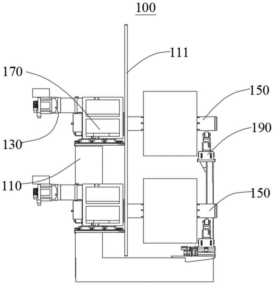
图1为本发明第一实施例提供的放卷装置的结构示意图;1 is a schematic structural diagram of an unwinding device provided by a first embodiment of the present invention;
图2为图1中第一支撑结构与气涨轴的连接结构示意图;Fig. 2 is a schematic diagram of the connection structure of the first support structure and the inflatable shaft in Fig. 1;
图3为图1中第二支撑结构在第一视角下的结构示意图;3 is a schematic structural diagram of the second support structure in FIG. 1 from a first viewing angle;
图4为图1中第二支撑结构在第二视角下的结构示意图;4 is a schematic structural diagram of the second support structure in FIG. 1 from a second viewing angle;
图5为图4中顶升承载机构的结构示意图。FIG. 5 is a schematic structural diagram of the jack-up bearing mechanism in FIG. 4 .
图标:100-放卷装置;110-机架;111-立板;130-驱动组件;131-电机支架;133-伺服电机;135-减速机;137-同步带;150-气涨轴;170-第一支撑结构;171-安装板;173-放卷轴承座;175-矩形焊接框架;177-第一直线导轨;190-第二支撑结构;191-底架;1911-横移导轨;1913-支架;192-定位件;193-横移驱动件;195-顶升承载机构;197-滑动底座;198-第二直线导轨;199-承载座体;1991-底板;1993-顶升驱动件;1995-顶板;1997-滚动支架;1999-滚动轴承。Icon: 100-unwinding device; 110-frame; 111-vertical plate; 130-drive assembly; 131-motor bracket; 133-servo motor; 135-reducer; 137-synchronous belt; 150-air shaft; 170 -1st support structure; 171-installation plate; 173-unwinding bearing seat; 175-rectangular welding frame; 177-first linear guide; 190-second support structure; 191-chassis; 1911-traverse guide; 1913-bracket; 192-positioning piece; 193-traverse driving piece; 195-jacking bearing mechanism; 197-sliding base; 198-second linear guide rail; 199-bearing seat body; 1991-base plate; Pieces; 1995 - top plate; 1997 - rolling support; 1999 - rolling bearing.
具体实施方式Detailed ways
为使本发明实施例的目的、技术方案和优点更加清楚,下面将结合本发明实施例中的附图,对本发明实施例中的技术方案进行清楚、完整地描述,显然,所描述的实施例是本发明一部分实施例,而不是全部的实施例。通常在此处附图中描述和示出的本发明实施例的组件可以以各种不同的配置来布置和设计。In order to make the purposes, technical solutions and advantages of the embodiments of the present invention clearer, the technical solutions in the embodiments of the present invention will be clearly and completely described below with reference to the accompanying drawings in the embodiments of the present invention. Obviously, the described embodiments These are some embodiments of the present invention, but not all embodiments. The components of the embodiments of the invention generally described and illustrated in the drawings herein may be arranged and designed in a variety of different configurations.
因此,以下对在附图中提供的本发明的实施例的详细描述并非旨在限制要求保护的本发明的范围,而是仅仅表示本发明的选定实施例。基于本发明中的实施例,本领域普通技术人员在没有作出创造性劳动前提下所获得的所有其他实施例,都属于本发明保护的范围。Thus, the following detailed description of the embodiments of the invention provided in the accompanying drawings is not intended to limit the scope of the invention as claimed, but is merely representative of selected embodiments of the invention. Based on the embodiments of the present invention, all other embodiments obtained by those of ordinary skill in the art without creative efforts shall fall within the protection scope of the present invention.
应注意到:相似的标号和字母在下面的附图中表示类似项,因此,一旦某一项在一个附图中被定义,则在随后的附图中不需要对其进行进一步定义和解释。It should be noted that like numerals and letters refer to like items in the following figures, so once an item is defined in one figure, it does not require further definition and explanation in subsequent figures.
在本发明的描述中,需要说明的是,术语“中心”、“上”、“竖直”、“水平”、“内”、“外”等指示的方位或位置关系为基于附图所示的方位或位置关系,或者是该发明产品使用时惯常摆放的方位或位置关系,仅是为了便于描述本发明和简化描述,而不是指示或暗示所指的装置或元件必须具有特定的方位、以特定的方位构造和操作,因此不能理解为对本发明的限制。此外,术语“第一”、“第二”等仅用于区分描述,而不能理解为指示或暗示相对重要性。In the description of the present invention, it should be noted that the orientation or positional relationship indicated by the terms "center", "upper", "vertical", "horizontal", "inner", "outer", etc. The orientation or positional relationship of the invention, or the orientation or positional relationship that is usually placed when the product of the invention is used, is only for the convenience of describing the present invention and simplifying the description, rather than indicating or implying that the device or element referred to must have a specific orientation, It is constructed and operated in a particular orientation and is therefore not to be construed as a limitation of the present invention. Furthermore, the terms "first", "second", etc. are only used to differentiate the description and should not be construed to indicate or imply relative importance.
在本发明的描述中,还需要说明的是,除非另有明确的规定和限定,术语“设置”、“相连”、“安装”、“连接”应做广义理解,例如,可以是固定连接,也可以是可拆卸连接,或一体地连接;可以是机械连接,也可以是电连接;可以是直接相连,也可以通过中间媒介间接相连,可以是两个元件内部的连通。对于本领域的普通技术人员而言,可以具体情况理解上述术语在本发明中的具体含义。In the description of the present invention, it should also be noted that, unless otherwise expressly specified and limited, the terms "arranged", "connected", "installed" and "connected" should be understood in a broad sense, for example, it may be a fixed connection, It can also be a detachable connection, or an integral connection; it can be a mechanical connection or an electrical connection; it can be a direct connection, or an indirect connection through an intermediate medium, or the internal communication between the two components. For those of ordinary skill in the art, the specific meanings of the above terms in the present invention can be understood in specific situations.
正如背景技术中所公开的,本领域内常规的放卷机构是通过将支撑结构直接安装在立板上来实现支撑的,而由于立板强度不够,且立板为竖直安装的板状结构,从而导致支撑结构的承载能力较差,导致气涨轴的承重量较小,目前承重量最多达到250kg左右,难以满足日益增涨的极片重量。本发明提供的一种放卷装置,通过将支撑结构的安装位置进行改变,同时改进其结构,使得其承重能力大大提高。As disclosed in the background art, the conventional unwinding mechanism in the art realizes the support by directly installing the support structure on the vertical plate, but because the vertical plate is not strong enough and the vertical plate is a vertically installed plate-like structure, As a result, the bearing capacity of the support structure is poor, resulting in a small bearing capacity of the air-expanded shaft. At present, the bearing capacity is at most about 250kg, which is difficult to meet the increasing pole piece weight. The unwinding device provided by the present invention greatly improves its load-bearing capacity by changing the installation position of the support structure and improving its structure at the same time.
下面结合附图,对本发明的一些实施方式作详细说明。在不冲突的情况下,下述的实施例中的特征可以相互组合。Some embodiments of the present invention will be described in detail below with reference to the accompanying drawings. The features of the embodiments described below may be combined with each other without conflict.
第一实施例first embodiment
结合参见图1和图2,本实施例提供了一种放卷装置100,承重能力强,能够防止立板111发生形变并影响放卷效果,同时上料方便。Referring to FIG. 1 and FIG. 2 in combination, the present embodiment provides an unwinding
本实施例提供的放卷装置100包括机架110、驱动组件130、气涨轴150、第一支撑结构170和第二支撑结构190,机架110上设置有立板111,第一支撑结构170设置在机架110上,气涨轴150可转动地设置在第一支撑结构170上,并穿过立板111向外伸出,驱动组件130设置在第一支撑结构170上并与气涨轴150传动连接,用于带动气涨轴150转动。所述第二支撑结构190设置在所述气涨轴150远离所述第一支撑结构170的一端并与所述气涨轴150的下侧滚动连接,用于支撑所述气涨轴150。The unwinding
在本实施例中,第一支撑结构170设置在机架110的方通之上,大大提高了整体的承载能力,以便承受动力电池大卷径的极片重量。同时立板111没有承载极片重量,不容易变形,提高了设备过辊的安装精度。In this embodiment, the
在本实施例中,第一支撑结构170设置在立板111后侧,第二支撑结构190设置在立板111前侧,通过第一支撑结构170和第二支撑结构190的共同支撑作用,能够进一步提高气涨轴150的承载能力。In this embodiment, the
需要说明的是,本实施例中气涨轴150为两根,方便放卷动作,同时第一支撑结构170和驱动组件130也为两个,两根第一支撑结构170间隔设置在机架110的方通上,两根驱动组件130分别驱动两根气涨轴150转动。同时第二支撑结构190能够同时支撑两个气涨轴150,具体支撑结构后续会详细介绍。It should be noted that, in this embodiment, there are two
第一支撑结构170包括安装板171和放卷轴承座173,安装板171固定设置在机架110上,放卷轴承座173设置在安装板171上,驱动组件130与放卷轴承座173连接,气涨轴150可转动地设置在放卷轴承座173上。具体地,安装板171固定焊接在机架110的方通之上,放卷轴承座173焊接在安装板171上,气涨轴150设置在放卷轴承座173上,放卷轴承座173能够承载气涨轴150上的极片。The
放卷轴承座173包括矩形焊接框架175和第一直线导轨177,第一直线导轨177设置在安装板171上,且第一直线导轨177的延伸方向与气涨轴150的轴线方向相平行,矩形焊接框架175滑动设置在第一直线导轨177上,驱动组件130与矩形焊接框架175连接,气涨轴150可转动地设置在矩形焊接框架175上。The
在本实施例中,通过矩形焊接框架175来承载气涨轴150,相比于常规的法兰型轴承座强度更高,且节约了制造成本。In this embodiment, the rectangular welded
在本实施例中,第一直线导轨177呈工字型结构,矩形焊接框架175的底部设置有扣合在第一直线导轨177上的卡套结构,通过该卡套结构能够使得矩形焊接框架175滑动设置在第一直线导轨177上,并在竖直方向上对矩形焊接框架175进行限位,防止矩形焊接框架175从第一直线导轨177上脱落。第一直线导轨177沿气涨轴150的轴向方向设置,即沿前后方向设置,通过设置第一直线导轨177,在承载矩形焊接框架175的同时,能够使得气涨轴150能够在前后方向移动,方便在放卷纠偏时调整气涨轴150的位置。In this embodiment, the first
在本实施例中,立板111上开设有供气涨轴150穿过的避让通孔,避让通孔的直径大于气涨轴150的直径,以使气涨轴150与立板111之间具有安装间隙。通过设置避让通孔,且避让通孔的孔径大于气涨轴150的直径,避免了气涨轴150与立板111之间接触,从而防止了气涨轴150上的承载力传递至立板111而导致立板111变形。In this embodiment, the
驱动组件130包括电机支架131、伺服电机133、减速机135和同步带137,电机支架131与放卷轴承座173连接,伺服电机133和减速机135均设置在电机支架131上,且伺服电机133与减速机135传动连接,同步带137分别与减速机135和气涨轴150连接,以使减速机135与气涨轴150传动连接。The
在本实施例中,电机支架131焊接设置在矩形焊接框架175上,同步带137分别缠绕设置在气涨轴150和减速机135的输出轴上,从而使得减速机135带动气涨轴150转动。当然,此处也可以直接采用步进电机带动气涨轴150转动。In this embodiment, the
结合参见图3至图5,第二支撑结构190包括底架191、横移驱动件193和顶升承载机构195,底架191设置在机架110上,且底架191上设置有横移导轨1911,顶升承载机构195滑动设置在横移导轨1911上,用于支撑气涨轴150,横移驱动件193设置在底架191上并与顶升承载机构195传动连接,用于带动顶升承载机构195沿横移导轨1911作往复运动。Referring to FIG. 3 to FIG. 5 in combination, the
在本实施例中,底架191焊接在机架110上,横移驱动件193为设置在底架191上的横向气缸,通过气缸带动顶升承载机构195沿横移导轨1911滑动,横移导轨1911沿水平方向设置,且横移导轨1911的延伸方向与气涨轴150的轴向相垂直,即通过横移驱动件193可带动顶升承载机构195沿靠近或者远离气涨轴150的方向移动,方便进行上料。In this embodiment, the
在本实施例中,底架191上还设置有定位件192,定位件192选择性地与顶升承载机构195连接,用于对顶升承载机构195进行限位。具体地,定位件192为定位气缸,其能够沿前后方向伸出或缩回,从而对顶升承载机构195进行限位或解除限位。In this embodiment, the
需要说明的是,本实施例中顶升承载机构195为两个,分别用于顶升支撑两根气涨轴150。具体地,底架191上还设置有支架1913,支架1913上设置有另一个顶升承载机构195,对另一根气涨轴150进行支撑。It should be noted that, in this embodiment, there are two lifting
顶升承载机构195包括滑动底座197、第二直线导轨198和承载座体199,滑动底座197滑动设置在横移导轨1911上,第二直线导轨198设置在滑动底座197上,承载座体199滑动设置在第二直线导轨198上,第二直线导轨198的延伸方向与气涨轴150的轴线方向相平行。The lifting
在本实施例中,第二直线导轨198的延伸方向与第一直线导轨177的延伸方向相平行,均为沿前后方向延伸,在放卷纠偏时,第一直线导轨177上的矩形焊接框架175和第二直线导轨198上的承载座体199同步前后运行,从而使得气涨轴150在保持支撑的情况下能够前后移动,方便纠偏动作。In this embodiment, the extending direction of the second
承载座体199包括底板1991、顶升驱动件1993和顶板1995,底板1991滑动设置在第二直线导轨198上,顶升驱动件1993设置在底板1991上并向上伸出,顶板1995与顶升驱动件1993连接并能够在顶升驱动件1993的带动下上升或下降,且顶板1995上设置有滚动支架1997,滚动支架1997上设置有两个用于与气涨轴150的下侧滚动连接的滚动轴承1999。通过设置顶升驱动件1993,能够带动顶板1995上设置的滚动支架1997上下运动,从而使得滚动支架1997上的滚动轴承1999与气涨轴150滚动接触或者脱离与气涨轴150的接触。The
需要说明的是,顶升驱动件1993为顶升气缸,气缸的缸体固定在底板1991上,气缸的活塞杆与顶板1995连接,从而实现带动顶板1995上下运动。实现第二支撑结构190的支撑高度的调节。It should be noted that the jacking
在本实施例中,滚动轴承1999上套设有尼龙套,且尼龙套不会滑落,能够进一步提高承载能力。In this embodiment, the rolling
需要说明的是,在上极片卷料时,通过横移驱动件193驱动顶升承载机构195沿横移导轨1911滑动,从而避让上料小车,上料完成后,气涨轴150通气涨大,顶升承载机构195通过横移驱动件193回复至气涨轴150的下方,同时定位件192伸出对顶升承载机构195进行定位。定位完成后,顶升驱动件1993向上顶升,使得滚动轴承1999滚动接触气涨轴150外圆,完成支撑动作。支撑动作完成后,第一支撑结构170处的伺服电机133开始工作,通过减速机135减速,再通过同步带137减速,从而带动气涨轴150转动。It should be noted that when the upper pole piece is coiled, the lifting
综上所述,本实施例提供的放卷装置100,通过将放卷轴承座173置于机架110的方通上,大大提高了整体的承载能力,同时避免了气涨轴150与立板111之间力的传递,防止立板111变形,提高了设备过辊的安装精度,同时第二支撑结构190中顶升承载机构195能够左右横向移动并能够定位,极大地方便上料小车进行上料,并通过设置第二支撑结构190实现了承载能力的补充,进一步提高了承载能力。To sum up, in the unwinding
第二实施例Second Embodiment
本实施例提供了一种叠片设备,包括放卷装置100、纠偏装置和叠片装置,其中放卷装置100的基本结构和原理及产生的技术效果和第一实施例相同,为简要描述,本实施例部分未提及之处,可参考第一实施例中相应内容。This embodiment provides a lamination device, including an
放卷装置100包括机架110、驱动组件130、气涨轴150和第一支撑结构170,机架110上设置有立板111,第一支撑结构170设置在机架110上,气涨轴150可转动地设置在第一支撑结构170上,并穿过立板111向外伸出,驱动组件130设置在第一支撑结构170上并与气涨轴150传动连接,用于带动气涨轴150转动。The unwinding
放卷装置100用于装载极片卷料,纠偏装置和叠片装置设置在立板111上,其中纠偏装置用于对放卷动作进行纠偏,叠片装置用于对切割后的极片进行叠片操作。The unwinding
以上所述仅为本发明的优选实施例而已,并不用于限制本发明,对于本领域的技术人员来说,本发明可以有各种更改和变化。凡在本发明的精神和原则之内,所作的任何修改、等同替换、改进等,均应包含在本发明的保护范围之内。The above descriptions are only preferred embodiments of the present invention, and are not intended to limit the present invention. For those skilled in the art, the present invention may have various modifications and changes. Any modification, equivalent replacement, improvement, etc. made within the spirit and principle of the present invention shall be included within the protection scope of the present invention.
Claims (10)
Priority Applications (1)
| Application Number | Priority Date | Filing Date | Title |
|---|---|---|---|
| CN202010177015.0A CN111232698B (en) | 2020-03-13 | 2020-03-13 | Unreeling device and lamination equipment |
Applications Claiming Priority (1)
| Application Number | Priority Date | Filing Date | Title |
|---|---|---|---|
| CN202010177015.0A CN111232698B (en) | 2020-03-13 | 2020-03-13 | Unreeling device and lamination equipment |
Publications (2)
| Publication Number | Publication Date |
|---|---|
| CN111232698A true CN111232698A (en) | 2020-06-05 |
| CN111232698B CN111232698B (en) | 2025-04-08 |
Family
ID=70880436
Family Applications (1)
| Application Number | Title | Priority Date | Filing Date |
|---|---|---|---|
| CN202010177015.0A Active CN111232698B (en) | 2020-03-13 | 2020-03-13 | Unreeling device and lamination equipment |
Country Status (1)
| Country | Link |
|---|---|
| CN (1) | CN111232698B (en) |
Cited By (1)
| Publication number | Priority date | Publication date | Assignee | Title |
|---|---|---|---|---|
| CN115724297A (en) * | 2022-12-13 | 2023-03-03 | 珠海市奥德维科技有限公司 | Coiled material drop feed mechanism |
Citations (6)
| Publication number | Priority date | Publication date | Assignee | Title |
|---|---|---|---|---|
| CN204528852U (en) * | 2015-04-16 | 2015-08-05 | 东莞市雅康精密机械有限公司 | The cutting apparatus of battery core materials |
| CN204866897U (en) * | 2015-06-11 | 2015-12-16 | 浙江大大不锈钢有限公司 | Coil of strip unwinding unit |
| CN105618613A (en) * | 2016-01-29 | 2016-06-01 | 湖北欢达电气股份有限公司 | Coiled plate feeding machine |
| CN208166132U (en) * | 2018-05-08 | 2018-11-30 | 成都冠佳科技有限公司 | Compounding machine |
| CN209097817U (en) * | 2018-11-23 | 2019-07-12 | 温州市浩特钢业有限公司 | A steel strip unwinding device |
| CN211971146U (en) * | 2020-03-13 | 2020-11-20 | 深圳吉阳智能科技有限公司 | Unwinding device and lamination equipment |
-
2020
- 2020-03-13 CN CN202010177015.0A patent/CN111232698B/en active Active
Patent Citations (6)
| Publication number | Priority date | Publication date | Assignee | Title |
|---|---|---|---|---|
| CN204528852U (en) * | 2015-04-16 | 2015-08-05 | 东莞市雅康精密机械有限公司 | The cutting apparatus of battery core materials |
| CN204866897U (en) * | 2015-06-11 | 2015-12-16 | 浙江大大不锈钢有限公司 | Coil of strip unwinding unit |
| CN105618613A (en) * | 2016-01-29 | 2016-06-01 | 湖北欢达电气股份有限公司 | Coiled plate feeding machine |
| CN208166132U (en) * | 2018-05-08 | 2018-11-30 | 成都冠佳科技有限公司 | Compounding machine |
| CN209097817U (en) * | 2018-11-23 | 2019-07-12 | 温州市浩特钢业有限公司 | A steel strip unwinding device |
| CN211971146U (en) * | 2020-03-13 | 2020-11-20 | 深圳吉阳智能科技有限公司 | Unwinding device and lamination equipment |
Cited By (2)
| Publication number | Priority date | Publication date | Assignee | Title |
|---|---|---|---|---|
| CN115724297A (en) * | 2022-12-13 | 2023-03-03 | 珠海市奥德维科技有限公司 | Coiled material drop feed mechanism |
| CN115724297B (en) * | 2022-12-13 | 2024-09-27 | 珠海市奥德维科技有限公司 | Coiled material discharging mechanism |
Also Published As
| Publication number | Publication date |
|---|---|
| CN111232698B (en) | 2025-04-08 |
Similar Documents
| Publication | Publication Date | Title |
|---|---|---|
| CN211971146U (en) | Unwinding device and lamination equipment | |
| CN111232698B (en) | Unreeling device and lamination equipment | |
| CN216996476U (en) | Plate arranging device and plate production line | |
| CN216228195U (en) | Strip steel width cutting guide device | |
| CN111252529A (en) | Move climbing mechanism on machine of carrying and jacking moves machine of carrying thereof | |
| CN220976483U (en) | Pallet fork | |
| CN222770563U (en) | Battery position correction mechanism for stacker used in heavy truck swap stations | |
| CN219078270U (en) | Lifting conveying device | |
| CN217229413U (en) | Door change gear stacking feeder for elevator door change gear bearing installation equipment | |
| CN215798254U (en) | Lifting transfer mechanism for conveying trays | |
| CN213164093U (en) | Coil cutting production equipment | |
| CN213701516U (en) | An automatic loading and unloading machine | |
| CN212023871U (en) | Main body frame of battery transfer device | |
| CN211004401U (en) | Roll transport device | |
| CN111302261B (en) | Lifting device for stereoscopic warehouse stacker | |
| CN218228946U (en) | Supporting frame for battery replacement robot of commercial vehicle battery replacement station | |
| CN210650477U (en) | Be used for new forms of energy battery detaching device | |
| CN214527169U (en) | Liftable coiled material unreeling machine | |
| CN222630669U (en) | Slitting machine support arm | |
| CN212042122U (en) | High-adaptability plate bending machine | |
| CN213387007U (en) | Automatic roll moving device | |
| CN219603160U (en) | Turning device and battery manufacturing equipment | |
| CN216186254U (en) | Automatic packing machine for tank body | |
| CN222153417U (en) | A feeding mechanism of a steel coil uncoiler | |
| CN222099095U (en) | Adjusting frame for paper feeder |
Legal Events
| Date | Code | Title | Description |
|---|---|---|---|
| PB01 | Publication | ||
| PB01 | Publication | ||
| SE01 | Entry into force of request for substantive examination | ||
| SE01 | Entry into force of request for substantive examination | ||
| GR01 | Patent grant | ||
| GR01 | Patent grant |