Double-layer sealing box with activated carbon circulating sealing device
Technical Field
The invention relates to the technical field of sealing, in particular to a double-layer sealing box with an activated carbon circulating sealing device.
Background
With the wider application of the seal box, the requirements on the sealing performance and the functional diversity of the seal box are stricter. In particular to the application fields of heat preservation boxes, safe cases, special box boxes and the like, and in order to achieve better sealing performance, a double-layer sealing structure box is provided.
In the existing double-layer sealed structure box, the strict sealing requirement is usually achieved by continuously introducing inert gas (such as argon) into the double-layer jacket of the sealed box. However, inert gases such as argon are expensive and cannot be recycled, the cost is high, the sealing requirement is strictly guaranteed, the cost can be controlled, and the economic efficiency is high. Because the double-layer sealed box is used for strictly controlling the water oxygen concentration in the box chamber, a substance which can react with water and oxidizing gas and has lower price can be found to replace argon gas so as to meet the sealing performance and the economical efficiency simultaneously.
Disclosure of Invention
Aiming at the problem that inert gases such as argon and the like are introduced into the double-layer sealing box jacket and the sealing performance and the economic cost are difficult to be considered, the invention provides the double-layer sealing box with the activated carbon circulating sealing device, which meets the strict sealing requirement and has good economical efficiency, and the specific technical scheme is as follows:
the invention provides a double-layer sealing box with an activated carbon circulating sealing device; the method is characterized in that: the method comprises the following steps: the device comprises an outer layer box body, an inner layer box body, an activated carbon input device, a top recovery device, a sampling detection device and an underground recovery device;
the outer-layer box body is formed by splicing a bottom plate and a plurality of outer plates, wherein the plurality of outer plates comprise a front outer plate, a top outer plate, a left outer plate, a right outer plate and a back outer plate; a plurality of outer plates are welded with the bottom plate in sequence to form an outer-layer box body;
the inner box body is wrapped in the outer box body, and the inner plates of the inner box body comprise a front inner plate, a top inner plate, a left inner plate, a right inner plate and a back inner plate; four side surfaces of the top inner plate are respectively welded with the inner surfaces of the front outer plate, the left outer plate, the right outer plate and the back outer plate, the left side surface and the right side surface of the front inner plate and the back inner plate are respectively welded with the inner surfaces of the left outer plate and the right outer plate, and a plurality of inner plates are sequentially welded with the bottom plate to form an inner-layer box body;
the activated carbon input device is communicated with the top outer plate and the back outer plate;
the sampling detection device is communicated with the back outer plate;
the top recovery device is communicated with the front outer plate;
the underground recovery device is communicated with the bottom plate;
thereby jointly forming a double-layer sealed box with an activated carbon circulating sealing device.
Further, the activated carbon input device comprises a feed inlet, a heat pipe, a reduction box, a rotary valve, a top conveying pipe, a side conveying pipe, a shaftless screw conveyor, a top partition plate, a first shut-off valve, a second shut-off valve and a third shut-off valve; wherein:
the feeding hole, the heat pipe and the reduction box are sequentially connected, the bottom of the reduction box is respectively connected with the top conveying pipe and the side conveying pipe, the first shut-off valve, the second shut-off valve and the third shut-off valve respectively control the opening and closing of the heat pipe, the reduction box and the top conveying pipe, the rotary valve controls the conveying speed of the side conveying pipe, and the top conveying pipe and the side conveying pipe respectively penetrate through the top outer plate and the side outer plate to be communicated with the top jacket and the side jacket; the top partition plate divides the top jacket into equal volumes, and each part after division is provided with a shaftless screw conveyor.
Further, the top recovery device comprises a top recovery box, a top feeding pipe, a first bucket elevator, a fourth shutoff valve and a fifth shutoff valve; wherein:
the top recovery box, the top feeding pipe and a feeding port of the first bucket elevator are sequentially connected together, the fourth shut-off valve and the fifth shut-off valve respectively control the opening and closing of the top recovery box and the top feeding pipe, the top recovery box penetrates through the front outer plate to be communicated with the top jacket, and a discharging port of the first bucket elevator is aligned with the feeding port.
Further, the sampling detection device comprises a sixth shutoff valve and a detection box, wherein the sixth shutoff valve controls the opening and closing of the detection box, the side partition plate divides the side jacket into parts in equal volume, and the detection box penetrates through the side outer plate and is communicated with the parts of the side jacket.
Furthermore, the underground recovery device comprises an underground material receiving pipe, a roller screen, a material crushing box, an underground recovery box, an underground feeding pipe, a second bucket elevator, a seventh shut-off valve, an eighth shut-off valve, a ninth shut-off valve and a tenth shut-off valve; wherein: the seventh shut-off valve, the eighth shut-off valve, the ninth shut-off valve and the tenth shut-off valve respectively control the opening and closing of the underground material receiving pipe, the crushed aggregate box, the underground recycling box and the underground feeding pipe, the underground material receiving pipe penetrates through the bottom plate and is communicated with the side portion jacket, the outlet of the underground material receiving pipe is aligned to the feeding end of the roller screen, the bottom of the roller screen is connected with the crushed aggregate box, the discharging end of the roller screen is aligned to the inlet of the underground recycling box, the underground feeding pipe and the feeding port of the second bucket elevator are sequentially connected together, and the discharging port of the second bucket elevator is aligned to the feeding port.
Further, in the activated carbon input device, activated carbon is poured into the feed inlet, then the first shut-off valve is opened to enable the activated carbon to enter the heat pipe, the first shut-off valve is closed, the heat pipe is heated to analyze the activated carbon, the second shut-off valve is opened to enable the analyzed activated carbon to enter the reduction box, the second shut-off valve is closed, the activated carbon is processed through a strong reducing agent in the reduction box to enable the activated carbon to be subjected to reduction reaction with oxidizing gas, then the processed activated carbon is conveyed into the top jacket and the side jacket through the top conveying pipe and the side conveying pipe by opening the third shut-off valve and controlling the rotary valve, and the activated carbon is filled in the whole jacket of the double-layer sealed box body through the gravity action of the shaftless screw conveyor and the activated carbon.
Furthermore, in the top recovery device, activated carbon reacted in the top jacket is recovered into the top recovery box by opening the fourth shutoff valve, then the fourth shutoff valve is closed, the fifth shutoff valve is opened, the top feeding pipe conveys the recovered activated carbon to the feeding hole again through the first bucket elevator, and the activated carbon reacted in the top jacket is recycled through the same process as that of the original activated carbon entering the feeding hole.
Furthermore, in the sampling detection device, a sixth shut-off valve is opened to enable a small amount of activated carbon to enter the detection box, and the reaction degree of the activated carbon, moisture and oxidizing gas is detected and fed back to a rotary valve in the activated carbon input device, so that the control of the conveying speed of the side conveying pipe is realized.
Furthermore, in the underground recovery device, a seventh shut-off valve is opened to convey the completely reacted activated carbon in the side jacket to a roller screen through an underground material receiving pipe, the seventh shut-off valve is closed, an eighth shut-off valve is opened, part of the broken activated carbon blocks are collected into a crushing box under the action of the roller screen, the activated carbon is recovered into the underground recovery box, a tenth shut-off valve is opened, the underground feeding pipe conveys the recovered activated carbon to the feeding port again through a second bucket elevator, and the principle of the underground recovery device is the same as that of the top recovery device, so that the reacted activated carbon in the side jacket can be recycled.
The invention has the beneficial effects that:
according to the double-layer sealing box with the activated carbon circulating sealing device, the jacket is formed between the inner layer box body and the outer layer box body through the double-layer box body structure, the top jacket and the side jacket are divided into equal volumes through the partition plates, the whole jacket is filled through the shaftless screw conveyor and the gravity action of activated carbon, the activated carbon after treatment has the capability of reacting with moisture and oxidizing gas due to the action of the heat pipe and the reduction box, the water oxygen concentration in the jacket is effectively reduced, the sealing performance is enhanced, the recycling of the activated carbon is realized through the recovery device, the activated carbon is low in price, the high cost caused by continuously introducing inert gases such as argon is greatly reduced, the sealing requirement is strictly guaranteed, the cost can be controlled, and the double-layer sealing box has good economy.
Drawings
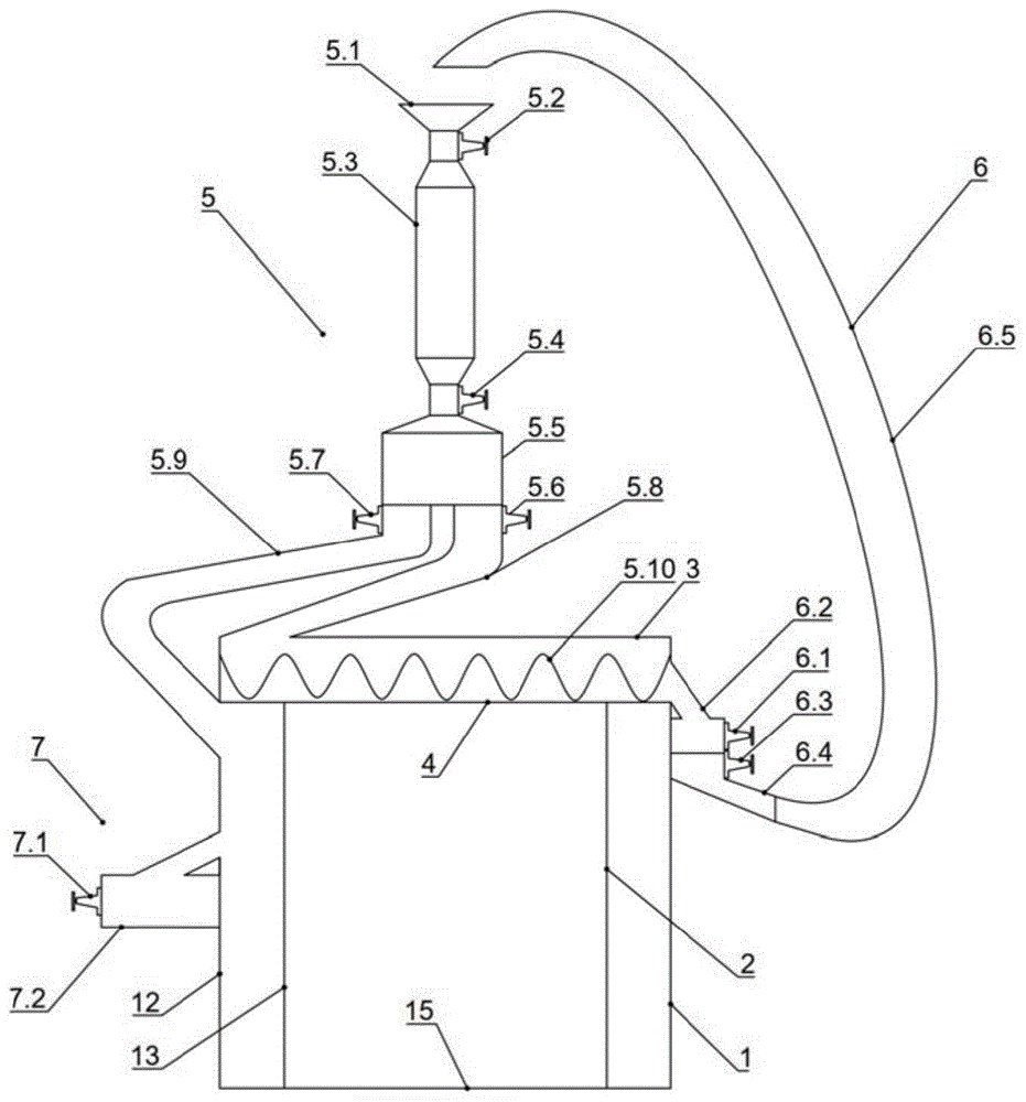
FIG. 1 is a schematic diagram of the overall structure of an embodiment of the invention (excluding underground recovery units);
FIG. 2 is a schematic view of an underground recovery unit in an embodiment of the present invention;
FIG. 3 is a schematic top view of a top jacket in an embodiment of the invention;
FIG. 4 is a schematic top view of a side jacket according to an embodiment of the present invention.
Fig. 5 is a three-dimensional perspective view of the overall structure in an embodiment of the present invention.
Reference numerals: 1-a front outer plate; 2-front inner plate; 3-a top outer plate; 4-a top inner panel; 5-an activated carbon input device; 5.1-feed inlet; 5.2 first shut-off valve; 5.3-heat pipe; 5.4 second shut-off valve; 5.5-reduction box; 5.6 third shut-off valve; 5.7-rotary valve; 5.8-top feed delivery pipe; 5.9-lateral feed delivery pipe; 5.10 shaftless screw conveyor; 5.11-top baffle; 6-top recovery unit; 6.1-fourth shutoff valve; 6.2-top recovery tank; 6.3-fifth shutoff valve; 6.4-top feeding pipe; 6.5-first bucket elevator; 7-sampling detection means; 7.1-sixth shutoff valve; 7.2-detection box; 8-left outer plate; 9-left inner panel; 10-right outer plate; 11-right inner panel; 12-a back outer plate; 13-back inner plate; 14-side baffles; 15-a base plate; 16-underground recovery units; 16.1-seventh shutoff valve; 16.2-underground receiving pipe; 16.3-roller screen; 16.4-eighth shutoff valve; 16.5-crushing box; 16.6-ninth shut-off valve; 16.7-underground recovery tank; 16.8-tenth shutoff valve; 16.9-underground feed pipes; 16.10-second bucket elevator.
Detailed Description
The present invention will be described in further detail with reference to examples and drawings, but the present invention is not limited to these examples.
As shown in fig. 1, 2, 4, this embodiment provides a double-layer sealing box having an activated carbon circulation sealing device; wherein:
the outer-layer box body is formed by splicing a bottom plate 15 and a plurality of outer plates, wherein the plurality of outer plates comprise a front outer plate 1, a top outer plate 3, a left outer plate 8, a right outer plate 10 and a back outer plate 12, and the plurality of outer plates and the bottom plate are welded in sequence to form the outer-layer box body;
the inner box body is wrapped in the outer box body and is formed by splicing a bottom plate 15 and a plurality of inner plates, the inner plates comprise a front inner plate 2, a top inner plate 4, a left inner plate 9, a right inner plate 11 and a back inner plate 13, four side surfaces of the top inner plate 4 are respectively welded with the inner surfaces of a front outer plate 1, a left outer plate 8, a right outer plate 10 and a back outer plate 12, the left side surface and the right side surface of the front inner plate 2 and the back inner plate 13 are respectively welded with the inner surfaces of the left outer plate 8 and the right outer plate 10, and the inner plates are sequentially welded with the bottom plate 15 to form the inner box body; the activated carbon input device 5 is communicated with the top outer plate 3 and the back outer plate 12, the sampling detection device 7 is communicated with the back outer plate 12, the top recovery device 6 is communicated with the front outer plate 1, and the underground recovery device 16 is communicated with the bottom plate 15, so that a double-layer sealing box with an activated carbon circulating sealing device is formed together.
As shown in fig. 1, 3 and 4, the activated carbon input device 5 comprises a feed inlet 5.1, a heat pipe 5.3, a reduction box 5.5, a rotary valve 5.7, a top feed pipe 5.8, a side feed pipe 5.9, a shaftless screw conveyor 5.10, a top partition plate 5.11, a first shut-off valve 5.2, a second shut-off valve 5.4 and a third shut-off valve 5.6, wherein the feed inlet 5.1, the heat pipe 5.3 and the reduction box 5.5 are connected in sequence, the bottom of the reduction box 5.5 is respectively connected with the top feed pipe 5.8 and the side feed pipe 5.9, the first shut-off valve 5.2, the second shut-off valve 5.4 and the third shut-off valve 5.6 respectively control the opening and closing of the heat pipe 5.3, the reduction box 5.5 and the top feed pipe 5.8, the side feed pipe 5.7 controls the feed speed of the side feed pipe 5.9, and the top feed pipe 5.8 and the side feed pipe 5.9 respectively pass through the jacket and the side jacket 3 and the side plate and the top plate and the outer plate.
As shown in fig. 3, the top partition 5.11 divides the top jacket into equal volumes of parts, each part being equipped with a shaftless screw conveyor 5.10;
as shown in fig. 1, the top recovery device 6 comprises a top recovery tank 6.2, a top feeding pipe 6.4, a first bucket elevator 6.5, a fourth shut-off valve 6.1 and a fifth shut-off valve 6.3;
the top recovery box 6.2, the top feeding pipe 6.4 and a feeding port of the first bucket elevator 6.5 are sequentially connected together, a fourth shut-off valve 6.1 and a fifth shut-off valve 6.3 respectively control the opening and closing of the top recovery box 6.2 and the top feeding pipe 6.4, the top recovery box 6.2 penetrates through the front outer plate 1 to be communicated with the top jacket, and a discharging port of the first bucket elevator 6.5 is aligned with the feeding port 5.1;
as shown in fig. 1 and 4, the sampling test device 7 includes a sixth shut-off valve 7.1 and a test box 7.2, the sixth shut-off valve 7.1 controls the opening and closing of the test box 7.2, the side partition plate 14 divides the side jacket into equal volumes, and the test box 7.2 is communicated with the side jacket parts through a side outer plate.
As shown in fig. 2, the underground recovery device 16 comprises an underground receiving pipe 16.2, a roller screen 16.3, a scrap box 16.5, an underground recovery box 16.7, an underground feeding pipe 16.9, a second bucket elevator 16.10, a seventh shut-off valve 16.1, an eighth shut-off valve 16.4, a ninth shut-off valve 16.6 and a tenth shut-off valve 16.8;
the seventh shut-off valve 16.1, the eighth shut-off valve 16.4, the ninth shut-off valve 16.6 and the tenth shut-off valve 16.8 respectively control opening and closing of the underground material receiving pipe 16.2, the scrap box 16.5, the underground recovery box 16.7 and the underground feed pipe 16.9, the underground material receiving pipe 16.2 penetrates through the bottom plate 15 to be communicated with the side portion jacket, an outlet of the underground material receiving pipe 16.2 is aligned with a feeding end of the roller screen 16.3, the bottom of the roller screen 16.3 is connected with the scrap box 16.5, a discharging end of the roller screen is aligned with an inlet of the underground recovery box 16.7, the underground feed pipe 16.9 and a feed port of the second bucket elevator 16.10 are sequentially connected together, and a discharge port of the second bucket elevator 16.10 is aligned with a feed port 5.1.
As shown in fig. 1, 2 and 5, in the activated carbon input device 5, firstly, activated carbon is poured into a feed inlet 5.1, then a first shut-off valve 5.2 is opened to enable the activated carbon to enter a heat pipe 5.3, the first shut-off valve 5.2 is closed, the heat pipe 5.3 is heated to a high temperature of about 800 ℃, the activated carbon is analyzed to be purer, a second shut-off valve 5.4 is opened to enable the analyzed activated carbon to enter a reduction box 5.5, the second shut-off valve 5.4 is closed, the activated carbon is treated by a strong reducing agent in the reduction box 5.5 to enable the activated carbon to be subjected to a reduction reaction with an oxidizing gas, and then the treated activated carbon is conveyed into a top jacket and a side jacket through a top conveying pipe 5.8 and a side conveying pipe 5.9 by opening a third shut-off valve 5.6 and a control rotary valve 5.7, and the whole jacket of a double-layer sealed box body is filled with the activated carbon by the gravity action of a shaftless screw conveyor 5.10 and the activated carbon;
in the top recovery device 6, activated carbon reacted in the top jacket is recovered into a top recovery box 6.2 by opening a fourth shut-off valve 6.1, then the fourth shut-off valve 6.1 is closed, a fifth shut-off valve 6.3 is opened, a top feeding pipe 6.4 conveys the recovered activated carbon to a feeding hole 5.1 again through a first bucket elevator 6.5, and the activated carbon reacted in the top jacket is recycled through the same process as that of the original activated carbon entering the feeding hole 5.1;
in the sampling detection device 7, a sixth shut-off valve 7.1 is opened to enable a small amount of activated carbon to enter a detection box 7.2, and the reaction degree of the activated carbon, moisture and oxidizing gas is detected and fed back to a rotary valve 5.7 in an activated carbon input device 5, so that the control of the material conveying speed of a side material conveying pipe 5.9 is realized;
in the underground recovery device 16, a seventh shut-off valve 16.1 is opened to convey the completely reacted activated carbon in the side part jacket to a roller screen 16.3 through an underground material receiving pipe 16.2, the seventh shut-off valve 16.1 is closed, an eighth shut-off valve 16.4 is opened, part of the broken activated carbon is collected into a broken material box 16.5 through the action of the roller screen 16.3, the more complete activated carbon is recovered into an underground recovery box 16.7, a tenth shut-off valve 16.8 is opened, the underground material conveying pipe 16.9 conveys the recovered activated carbon to a material inlet 5.1 again through a second bucket elevator 16.10, and the principle is the same as that of the top recovery device 6, so that the reacted activated carbon in the side part jacket is recycled.
According to the double-layer sealing box with the activated carbon circulating sealing device, the jacket is formed between the inner layer box body and the outer layer box body through the double-layer box body structure, the treated activated carbon has the capability of reacting with moisture and oxidizing gas through the action of the heat pipe and the reduction box, so that the water oxygen concentration in the jacket of the box body can be strictly controlled, the strict sealing requirement is met, the recycling of the activated carbon is realized through the recovery device, the cost of the activated carbon is lower, and the sealing performance is met while the economic performance is good.
It should be noted that the above-mentioned embodiments are only preferred embodiments of the present invention, and not intended to limit the present invention, and although the present invention has been described in detail with reference to the foregoing embodiments, it will be apparent to those skilled in the art that modifications and equivalents can be made in the technical solutions described in the foregoing embodiments, or some technical features of the present invention may be substituted. Any modification, equivalent replacement, or improvement made within the spirit and principle of the present invention should be included in the protection scope of the present invention.