CN111217274A - A hang in midair hoist that is used for assembled buckling restrained steel plate wall quick, high-efficient assembly - Google Patents

A hang in midair hoist that is used for assembled buckling restrained steel plate wall quick, high-efficient assembly Download PDF

Info

Publication number
CN111217274A
CN111217274A CN202010194782.2A CN202010194782A CN111217274A CN 111217274 A CN111217274 A CN 111217274A CN 202010194782 A CN202010194782 A CN 202010194782A CN 111217274 A CN111217274 A CN 111217274A
Authority
CN
China
Prior art keywords
lifting lug
steel plate
buckling
plate wall
shackle
Prior art date
Legal status (The legal status is an assumption and is not a legal conclusion. Google has not performed a legal analysis and makes no representation as to the accuracy of the status listed.)
Pending
Application number
CN202010194782.2A
Other languages
Chinese (zh)
Inventor
张学生
李铁兵
李海兵
于巍
程欣荣
屈晨
潘霞
李化
张彬
Current Assignee (The listed assignees may be inaccurate. Google has not performed a legal analysis and makes no representation or warranty as to the accuracy of the list.)
Beijing Urban Construction Group Co Ltd
Original Assignee
Beijing Urban Construction Group Co Ltd
Priority date (The priority date is an assumption and is not a legal conclusion. Google has not performed a legal analysis and makes no representation as to the accuracy of the date listed.)
Filing date
Publication date
Application filed by Beijing Urban Construction Group Co Ltd filed Critical Beijing Urban Construction Group Co Ltd
Priority to CN202010194782.2A priority Critical patent/CN111217274A/en
Publication of CN111217274A publication Critical patent/CN111217274A/en
Pending legal-status Critical Current

Links

Images

Classifications

    • B—PERFORMING OPERATIONS; TRANSPORTING
    • B66—HOISTING; LIFTING; HAULING
    • B66D—CAPSTANS; WINCHES; TACKLES, e.g. PULLEY BLOCKS; HOISTS
    • B66D3/00—Portable or mobile lifting or hauling appliances
    • B66D3/12—Chain or like hand-operated tackles with or without power transmission gearing between operating member and lifting rope, chain or cable
    • B—PERFORMING OPERATIONS; TRANSPORTING
    • B66—HOISTING; LIFTING; HAULING
    • B66C—CRANES; LOAD-ENGAGING ELEMENTS OR DEVICES FOR CRANES, CAPSTANS, WINCHES, OR TACKLES
    • B66C1/00—Load-engaging elements or devices attached to lifting or lowering gear of cranes or adapted for connection therewith for transmitting lifting forces to articles or groups of articles
    • B66C1/10—Load-engaging elements or devices attached to lifting or lowering gear of cranes or adapted for connection therewith for transmitting lifting forces to articles or groups of articles by mechanical means
    • B66C1/62—Load-engaging elements or devices attached to lifting or lowering gear of cranes or adapted for connection therewith for transmitting lifting forces to articles or groups of articles by mechanical means comprising article-engaging members of a shape complementary to that of the articles to be handled
    • B66C1/66—Load-engaging elements or devices attached to lifting or lowering gear of cranes or adapted for connection therewith for transmitting lifting forces to articles or groups of articles by mechanical means comprising article-engaging members of a shape complementary to that of the articles to be handled for engaging holes, recesses, or abutments on articles specially provided for facilitating handling thereof
    • E—FIXED CONSTRUCTIONS
    • E04—BUILDING
    • E04G—SCAFFOLDING; FORMS; SHUTTERING; BUILDING IMPLEMENTS OR AIDS, OR THEIR USE; HANDLING BUILDING MATERIALS ON THE SITE; REPAIRING, BREAKING-UP OR OTHER WORK ON EXISTING BUILDINGS
    • E04G21/00—Preparing, conveying, or working-up building materials or building elements in situ; Other devices or measures for constructional work
    • E04G21/14—Conveying or assembling building elements
    • E04G21/16—Tools or apparatus
    • E04G21/167—Tools or apparatus specially adapted for working-up plates, panels or slab shaped building elements

Landscapes

  • Engineering & Computer Science (AREA)
  • Architecture (AREA)
  • Mechanical Engineering (AREA)
  • Civil Engineering (AREA)
  • Structural Engineering (AREA)
  • Conveying And Assembling Of Building Elements In Situ (AREA)

Abstract

本发明公开了一种用于防屈曲钢板墙快速、高效装配的悬吊吊具,包括:悬挂吊具和卸扣,所述悬挂吊具中设有第一吊耳和第二吊耳,所述第一吊耳和第二吊耳上均设有一组安装孔,所述第一吊耳和第二吊耳相对设置于钢梁的两侧,所述卸扣穿于安装孔中对第一吊耳和第二吊耳进行连接,所述卸扣上设有悬挂式葫芦,所述悬挂式葫芦上设有倒链,所述倒链的一端穿于固定扣,所述固定扣设于防屈曲钢板墙的两侧。本发明结构简单,易于制造,将悬挂吊具安装到H钢梁上,将其作为悬挂受力点,利用两卸扣作为第一吊耳和第二吊耳的连接件,形成一个稳定的吊装结构,无需在原结构上焊接吊耳,可以重复多次使用,节约材料,提高安装效率,对原结构不会损坏。

Figure 202010194782

The invention discloses a suspension hanger for fast and efficient assembly of an anti-buckling steel plate wall, comprising: a suspension hanger and a shackle, wherein the suspension hanger is provided with a first lifting lug and a second lifting lug, and the The first lifting lug and the second lifting lug are both provided with a set of mounting holes, the first lifting lug and the second lifting lug are oppositely arranged on both sides of the steel beam, and the shackle is passed through the mounting holes for the first lifting lug. The lifting lug and the second lifting lug are connected, the shackle is provided with a hanging hoist, and the hanging hoist is provided with an inverted chain, one end of the inverted chain is passed through the fixed buckle, and the fixed buckle is arranged on the anti Both sides of a buckling steel plate wall. The invention is simple in structure and easy to manufacture. The hanging sling is installed on the H steel beam, which is used as the suspension force point, and the two shackles are used as the connecting parts of the first lifting lug and the second lifting lug to form a stable hoisting device. It can be used repeatedly, save materials, improve installation efficiency, and will not damage the original structure.

Figure 202010194782

Description

A hang in midair hoist that is used for assembled buckling restrained steel plate wall quick, high-efficient assembly
Technical Field
The invention belongs to the technical field of steel structure buildings, and particularly relates to a suspension hanger for quickly and efficiently assembling a buckling-restrained steel plate wall.
Background
With the rapid development of social economy, the living standard and the living quality of people are continuously improved, and the rhythm of people is continuously accelerated in both production and life, as well as the construction industry. At present, people are most of concrete buildings no matter in office places or houses, people know that the construction period of the concrete buildings is long, the construction period is seriously influenced by weather, particularly in winter, people can see that after the buildings are below zero in winter, a plurality of construction sites stop working, so that the period of the whole building is long, meanwhile, the labor required by the concrete building construction is complicated, and large workers, small workers, woodworkers, tile workers and the like have high requirements on personnel, and along with the continuous increase of materials and labor cost, the cost of the whole building is high, and the input cost is higher and higher; and with the increasing requirements of people on life and work, the generation of steel structure buildings is promoted due to the fact that more and more young people do not want to engage in the building industry again and the like. Through continuous technical innovation, the generation of the assembly type building is promoted.
Buckling restrained steel plate wall is the common wall body in the prefabricated building, it is at the in-process of construction, need hoist it to the high altitude construction of installing, however its is bulky, a great deal of difficulty has been brought for the hoist and mount, conventional hoist and mount mostly all carry out welded fastening with hoist and wall body and the girder steel of waiting to install the position, rethread hoist mechanism hoists it, whole process is comparatively loaded down with trivial details, and unable reuse, consuming time power, therefore the current hoist of buckling restrained steel plate wall that is used for still remains to improve.
Disclosure of Invention
The purpose of the invention is as follows: in order to overcome the defects, the invention aims to provide the suspension lifting appliance for quickly and efficiently assembling the anti-buckling steel plate wall, which has the advantages of simple structure, reasonable design, easiness in manufacturing, no need of welding lifting lugs on the original structure, detachability, repeated use, material saving, improvement on the installation efficiency and no damage to the original structure.
The technical scheme is as follows: in order to achieve the above object, the present invention provides a suspension hanger for rapid and efficient assembly of buckling restrained steel plate walls, comprising: hang hoist and shackle, be equipped with first lug and second lug in the hoist that hangs, all be equipped with a set of mounting hole on first lug and the second lug, first lug and second lug set up in the both sides of girder steel relatively, the shackle is worn and is connected first lug and second lug in the mounting hole, be equipped with the suspension type calabash on the shackle, be equipped with the chain block on the suspension type calabash, the one end of chain block is worn in the fixed knot, the both sides of buckling restrained plate wall are located to the fixed knot.
The suspension hanger for the rapid and efficient assembly of the buckling-restrained steel plate wall is simple in structure and easy to manufacture, the suspension hanger is mounted on an H-shaped steel beam and serves as a suspension stress point, two shackles are used as connecting pieces of a first lifting lug and a second lifting lug to form a stable hoisting structure, the lifting lugs are not required to be welded on an original structure and can be detached, the suspension hanger can be repeatedly used, materials are saved, the mounting efficiency is improved, the original structure cannot be damaged, and the construction requirements can be better met.
According to the invention, the first lifting lug and the second lifting lug are respectively provided with the cutting plate and the hook plate, the hook plate is arranged above the cutting plate, a U-shaped groove is arranged between the cutting plate and the hook plate, the mounting hole is formed in the cutting plate, and the U-shaped groove is matched with the steel beam.
According to the invention, the first lifting lug and the second lifting lug are oppositely arranged, and the distance between the hook plate on the first lifting lug and the hook plate on the second lifting lug is matched with the steel beam.
The shackle is U-shaped, the two ends of the shackle are provided with the ear rings, the ear rings are provided with the through holes, the shackle is clamped below the knife boards in the first lifting lug and the second lifting lug, and the ear rings and the knife boards are connected through the connecting piece.
The fixing buckle is internally provided with a fixing seat and an installation buckle, the fixing seat is fixed with the buckling-restrained steel plate wall, the installation buckle is arranged on one side of the fixing seat, and the inverted chain penetrates through the installation buckle.
The fixing buckle is internally provided with an embedded threaded sleeve and a detachable lifting ring, the embedded threaded sleeve is fixed on the anti-buckling steel plate wall through a bolt, and the detachable lifting ring is arranged on the embedded threaded sleeve.
The working method of the suspension hanger for quickly and efficiently assembling the anti-buckling steel plate wall, disclosed by the invention, comprises the following specific working methods:
1): firstly, hanging lifting appliances are arranged on two sides of a steel beam, namely a first lifting lug and a second lifting lug are respectively clamped on two sides of the steel beam, and the first lifting lug and the second lifting lug are locked through shackles;
2): meanwhile, fixing the fixing buckle on the anti-buckling steel plate wall through a bolt;
3): then the suspension type hoist is hooked on the shackle, and a side chain block on the suspension type hoist is penetrated in a detachable hanging ring of the fixing buckle;
4): and then, the other chain block is pulled, so that the buckling-restrained steel plate wall is hoisted until the buckling-restrained steel plate wall is hoisted to a proper position.
The technical scheme shows that the invention has the following beneficial effects:
the suspension hanger for the rapid and efficient assembly of the buckling-restrained steel plate wall is simple in structure and easy to manufacture, the suspension hanger is mounted on an H-shaped steel beam and serves as a suspension stress point, two shackles are used as connecting pieces of a first lifting lug and a second lifting lug to form a stable hoisting structure, the lifting lugs are not required to be welded on an original structure and can be detached, the suspension hanger can be repeatedly used, materials are saved, the mounting efficiency is improved, the original structure cannot be damaged, and the construction requirements can be better met.
Drawings
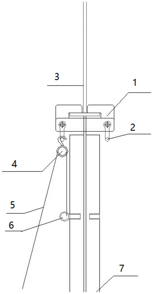
Fig. 1 is a schematic view of the installation structure of a suspension spreader according to the present invention;
fig. 2 is a schematic structural diagram of the suspension hanger of the invention, wherein a is a structural diagram of a first lifting lug, B is a structural diagram of a second lifting lug, and C is a schematic mounting diagram of the first lifting lug and the second lifting lug;
figure 3 is a cross-sectional view of the shackle of the present invention.
Detailed Description
The invention is further elucidated with reference to the drawings and the embodiments.
Example 1
Reference will now be made in detail to embodiments of the present invention, examples of which are illustrated in the accompanying drawings, wherein like or similar reference numerals refer to the same or similar elements or elements having the same or similar function throughout. The embodiments described below with reference to the drawings are illustrative and intended to be illustrative of the invention and are not to be construed as limiting the invention.
In the description of the present invention, it is to be understood that the terms "center", "longitudinal", "lateral", "length", "width", "thickness", "upper", "lower", "front", "rear", "left", "right", "vertical", "horizontal", "top", "bottom", "inner", "clockwise", "counterclockwise", and the like, indicate orientations and positional relationships based on those shown in the drawings, and are used only for convenience of description and simplicity of description, and do not indicate or imply that the device or element being referred to must have a particular orientation, be constructed and operated in a particular orientation, and thus, are not to be considered as limiting the present invention.
Furthermore, the terms "first", "second" and "first" are used for descriptive purposes only and are not to be construed as indicating or implying relative importance or implicitly indicating the number of technical features indicated. Thus, a feature defined as "first" or "second" may explicitly or implicitly include one or more of that feature. In the description of the present invention, unless otherwise specified, "a plurality" means two or more unless explicitly defined otherwise.
In the present invention, unless otherwise expressly specified or limited, the terms "mounted," "connected," "secured," and the like are to be construed broadly and can, for example, be fixedly connected, detachably connected, or integrally connected; can be mechanically or electrically connected; they may be connected directly or indirectly through intervening media, or they may be interconnected between two elements. The specific meanings of the above terms in the present invention can be understood by those skilled in the art according to specific situations.
In the present invention, unless otherwise expressly stated or limited, "above" or "below" a first feature means that the first and second features are in direct contact, or that the first and second features are not in direct contact but are in contact with each other via another feature therebetween. Also, the first feature being "on," "above" and "over" the second feature includes the first feature being directly on and obliquely above the second feature, or merely indicating that the first feature is at a higher level than the second feature. A first feature being "under," "below," and "beneath" a second feature includes the first feature being directly under and obliquely below the second feature, or simply meaning that the first feature is at a lesser elevation than the second feature.
A suspension spreader for the rapid, efficient assembly of buckling restrained steel panel walls as shown in the drawings, comprising: hang hoist 1 and shackle 2, be equipped with first lug 11 and second lug 12 in hanging hoist 1, all be equipped with a set of mounting hole 13 on first lug 11 and the second lug 12, first lug 11 and second lug 12 set up in the both sides of girder steel 3 relatively, shackle 2 wears to connect first lug 11 and second lug 12 in mounting hole 13, be equipped with suspension type calabash 4 on shackle 2, be equipped with chain block 5 on the suspension type calabash 4, the one end of chain block 5 is worn in the knot 6, the both sides of buckling-restrained steel plate wall 7 are located to knot 6.
Further, a knife plate 14 and a hook plate 15 are arranged on each of the first lifting lug 11 and the second lifting lug 12, the hook plate 15 is arranged above the knife plate 14, a U-shaped groove 16 is arranged between the hook plate 15 and the knife plate 14, the mounting hole 13 is arranged on the knife plate 14, and the U-shaped groove 16 is matched with the steel beam 3.
Preferably, the first lifting lug 11 and the second lifting lug 12 are oppositely arranged, and the distance between the hook plate 15 on the first lifting lug 11 and the hook plate 15 on the second lifting lug 12 is matched with the steel beam 3.
Furthermore, the shackle 2 is U-shaped, two ends of the shackle are provided with ear rings 21, the ear rings 21 are provided with through holes 22, the shackle 2 is clamped below the knife board 14 in the first lifting lug 11 and the second lifting lug 12, and the ear rings 21 and the knife board 14 are connected through a connecting piece.
Furthermore, a fixing seat and an installation buckle are arranged in the fixing buckle 5, the fixing seat is fixed with the buckling-restrained steel plate wall 6, the installation buckle is arranged on one side of the fixing seat, and the inverted chain 4 penetrates through the installation buckle.
Example 2
A suspension spreader for the rapid, efficient assembly of buckling restrained steel panel walls as shown in the drawings, comprising: hang hoist 1 and shackle 2, be equipped with first lug 11 and second lug 12 in hanging hoist 1, all be equipped with a set of mounting hole 13 on first lug 11 and the second lug 12, first lug 11 and second lug 12 set up in the both sides of girder steel 3 relatively, shackle 2 wears to connect first lug 11 and second lug 12 in mounting hole 13, be equipped with suspension type calabash 4 on shackle 2, be equipped with chain block 5 on the suspension type calabash 4, the one end of chain block 5 is worn in the knot 6, the both sides of buckling-restrained steel plate wall 7 are located to knot 6.
Further, a knife plate 14 and a hook plate 15 are arranged on each of the first lifting lug 11 and the second lifting lug 12, the hook plate 15 is arranged above the knife plate 14, a U-shaped groove 16 is arranged between the hook plate 15 and the knife plate 14, the mounting hole 13 is arranged on the knife plate 14, and the U-shaped groove 16 is matched with the steel beam 3.
Preferably, the first lifting lug 11 and the second lifting lug 12 are oppositely arranged, and the distance between the hook plate 15 on the first lifting lug 11 and the hook plate 15 on the second lifting lug 12 is matched with the steel beam 3.
Furthermore, the shackle 2 is U-shaped, two ends of the shackle are provided with ear rings 21, the ear rings 21 are provided with through holes 22, the shackle 2 is clamped below the knife board 14 in the first lifting lug 11 and the second lifting lug 12, and the ear rings 21 and the knife board 14 are connected through a connecting piece.
Furthermore, a fixing seat and an installation buckle are arranged in the fixing buckle 5, the fixing seat is fixed with the buckling-restrained steel plate wall 6, the installation buckle is arranged on one side of the fixing seat, and the inverted chain 4 penetrates through the installation buckle.
Further preferably, be equipped with embedded threaded sleeve and can dismantle rings in the fixed knot 6, embedded threaded sleeve is fixed in on buckling-restrained steel plate wall 7 through the bolt, can dismantle rings and locate on embedded threaded sleeve.
The working method of the suspension hanger for the rapid and efficient assembly of the buckling-restrained steel plate wall in the embodiment comprises the following specific working methods:
1: firstly, hanging slings 1 are arranged on two sides of a steel beam 3, namely a first lifting lug 11 and a second lifting lug 12 are respectively clamped on two sides of the steel beam 3, and then the first lifting lug 11 and the second lifting lug 12 are locked through shackles 2;
2: meanwhile, the fixing buckle 6 is fixed on the buckling-restrained steel plate wall 7 through bolts;
3: then the suspension type hoist 4 is hooked on the shackle 2, and a side chain block 5 on the suspension type hoist 4 is inserted into a detachable hanging ring of the fixing buckle 6;
4: and then, the other chain block 5 is pulled, so that the buckling-restrained steel plate wall 7 is hoisted until the buckling-restrained steel plate wall is hoisted to a proper position.
The foregoing is only a preferred embodiment of the present invention, and it should be noted that modifications can be made by those skilled in the art without departing from the principle of the present invention, and these modifications should also be construed as the protection scope of the present invention.

Claims (7)

1.一种用于防屈曲钢板墙快速、高效装配的悬吊吊具,其特征在于:包括:悬挂吊具(1)和卸扣(2),所述悬挂吊具(1)中设有第一吊耳(11)和第二吊耳(12),所述第一吊耳(11)和第二吊耳(12)上均设有一组安装孔(13),所述第一吊耳(11)和第二吊耳(12)相对设置于钢梁(3)的两侧,所述卸扣(2)穿于安装孔(13)中对第一吊耳(11)和第二吊耳(12)进行连接,所述卸扣(2)上设有悬挂式葫芦(4),所述悬挂式葫芦(4)上设有倒链(5),所述倒链(5)远离悬挂吊具(1)的一端穿于固定扣(6)中,所述固定扣(6)设于防屈曲钢板墙(7)的两侧。1. A suspension spreader for fast and efficient assembly of an anti-buckling steel plate wall, characterized in that it comprises: a suspension spreader (1) and a shackle (2), wherein the suspension spreader (1) is provided with A first lifting lug (11) and a second lifting lug (12), the first lifting lug (11) and the second lifting lug (12) are both provided with a set of mounting holes (13), and the first lifting lug (12) is provided with a set of mounting holes (13). (11) and the second lifting lug (12) are oppositely arranged on both sides of the steel beam (3). The ears (12) are connected, the shackle (2) is provided with a hanging hoist (4), and the hanging hoist (4) is provided with an inverted chain (5), the inverted chain (5) is far from the hanging One end of the spreader (1) is passed through the fixing buckle (6), and the fixing buckle (6) is arranged on both sides of the anti-buckling steel plate wall (7). 2.根据权利要求1所述的用于防屈曲钢板墙快速、高效装配的悬吊吊具,其特征在于:所述第一吊耳(11)和第二吊耳(12)上均设有刀板(14)和钩板(15),所述钩板(15)设于刀板(14)的上方,且两者之间设有U型槽(16),所述安装孔(13)设于刀板(14)上,所述U型槽(16)与钢梁(3)相配合。2. The suspension hanger for fast and efficient assembly of a buckling-resistant steel plate wall according to claim 1, wherein the first lifting lug (11) and the second lifting lug (12) are both provided with A knife plate (14) and a hook plate (15), the hook plate (15) is arranged above the knife plate (14), and a U-shaped groove (16) is arranged between the two, and the mounting hole (13) It is arranged on the blade (14), and the U-shaped groove (16) is matched with the steel beam (3). 3.根据权利要求1所述的用于防屈曲钢板墙快速、高效装配的悬吊吊具,其特征在于:所述第一吊耳(11)和第二吊耳(12)相对设置,且所述第一吊耳(11)上的钩板(15)和第二吊耳(12)上的钩板(15)之间的间距与钢梁(3)相匹配。3. The suspension hanger for fast and efficient assembly of a buckling-resistant steel plate wall according to claim 1, wherein the first lifting lug (11) and the second lifting lug (12) are arranged opposite to each other, and The distance between the hook plate (15) on the first lifting lug (11) and the hook plate (15) on the second lifting lug (12) matches the steel beam (3). 4.根据权利要求1所述的用于防屈曲钢板墙快速、高效装配的悬吊吊具,其特征在于:所述卸扣(2)呈U字型,其两端设有耳圈(21),所述耳圈(21)上设有穿孔(22),所述卸扣(2)卡于第一吊耳(11)和第二吊耳(12)中的刀板(14)下方,并通过连接件对耳圈(21)与刀板(14)进行连接。4. The suspension hanger for fast and efficient assembly of a buckling-resistant steel plate wall according to claim 1, characterized in that: the shackle (2) is U-shaped, with ear loops (21) at both ends of the shackle (2). ), the ear ring (21) is provided with a perforation (22), the shackle (2) is clamped under the knife plate (14) in the first lifting lug (11) and the second lifting lug (12), The ear loop (21) and the blade (14) are connected through the connecting piece. 5.根据权利要求1所述的用于防屈曲钢板墙快速、高效装配的悬吊吊具,其特征在于:所述固定扣(5)中设有固定座和安装扣,所述固定座与防屈曲钢板墙(7)固定,所述安装扣设于固定座的一侧,所述倒链(4)穿于安装扣中。5. The suspension hanger for fast and efficient assembly of a buckling-resistant steel plate wall according to claim 1, characterized in that: the fixing buckle (5) is provided with a fixing seat and a mounting buckle, and the fixing seat is connected to The anti-buckling steel plate wall (7) is fixed, the installation buckle is arranged on one side of the fixed seat, and the reverse chain (4) is passed through the installation buckle. 6.根据权利要求1所述的用于防屈曲钢板墙快速、高效装配的悬吊吊具,其特征在于:所述固定扣(6)中设有内嵌螺纹套筒和可拆卸吊环,所述内嵌螺纹套筒通过螺栓固定于防屈曲钢板墙(7)上,所述可拆卸吊环设于内嵌螺纹套筒上。6. The suspension hanger for fast and efficient assembly of anti-buckling steel plate walls according to claim 1, characterized in that: the fixing buckle (6) is provided with an embedded threaded sleeve and a detachable lifting ring, so The embedded threaded sleeve is fixed on the anti-buckling steel plate wall (7) by bolts, and the detachable lifting ring is arranged on the embedded threaded sleeve. 7.根据权利要求1至6中任一项所述的用于防屈曲钢板墙快速、高效装配的悬吊吊具的工作方法,其特征在于:具体的工作方法如下:7. The working method of the suspension spreader for fast and efficient assembly of the anti-buckling steel plate wall according to any one of claims 1 to 6, characterized in that: the specific working method is as follows: 1):首先悬挂吊具(1)设于钢梁(3)的两侧,即第一吊耳(11)和第二吊耳(12)分别卡于钢梁(3)的两侧,再通过卸扣(2)对第一吊耳(11)和第二吊耳(12)进行锁紧;1): First, the hanger (1) is set on both sides of the steel beam (3), that is, the first lifting lug (11) and the second lifting lug (12) are respectively clamped on both sides of the steel beam (3), and then The first lifting lug (11) and the second lifting lug (12) are locked by the shackle (2); 2):与此同时,将固定扣(6)通过螺栓固定于防屈曲钢板墙(7)上;2): At the same time, fix the fixing buckle (6) on the anti-buckling steel plate wall (7) by bolts; 3):然后将悬挂式葫芦(4)勾住卸扣(2),并将悬挂式葫芦(4)上的一侧倒链(5)穿于固定扣(6)的可拆卸吊环中;3): Then hook the hanging hoist (4) to the shackle (2), and put the reverse chain (5) on one side of the hanging hoist (4) into the detachable lifting ring of the fixing buckle (6); 4):然后通过拉动另一根倒链(5),从而对防屈曲钢板墙(7)实现吊装,直至将其吊装到合适位置即可。4): Then, by pulling another inverted chain (5), the anti-buckling steel plate wall (7) can be hoisted until it is hoisted to a suitable position.
CN202010194782.2A 2020-03-19 2020-03-19 A hang in midair hoist that is used for assembled buckling restrained steel plate wall quick, high-efficient assembly Pending CN111217274A (en)

Priority Applications (1)

Application Number Priority Date Filing Date Title
CN202010194782.2A CN111217274A (en) 2020-03-19 2020-03-19 A hang in midair hoist that is used for assembled buckling restrained steel plate wall quick, high-efficient assembly

Applications Claiming Priority (1)

Application Number Priority Date Filing Date Title
CN202010194782.2A CN111217274A (en) 2020-03-19 2020-03-19 A hang in midair hoist that is used for assembled buckling restrained steel plate wall quick, high-efficient assembly

Publications (1)

Publication Number Publication Date
CN111217274A true CN111217274A (en) 2020-06-02

Family

ID=70813368

Family Applications (1)

Application Number Title Priority Date Filing Date
CN202010194782.2A Pending CN111217274A (en) 2020-03-19 2020-03-19 A hang in midair hoist that is used for assembled buckling restrained steel plate wall quick, high-efficient assembly

Country Status (1)

Country Link
CN (1) CN111217274A (en)

Cited By (1)

* Cited by examiner, † Cited by third party
Publication number Priority date Publication date Assignee Title
CN111874825A (en) * 2020-06-12 2020-11-03 中国二冶集团有限公司 Construction method for hoisting component by using unconventional hoisting equipment

Citations (8)

* Cited by examiner, † Cited by third party
Publication number Priority date Publication date Assignee Title
KR20130073616A (en) * 2011-12-23 2013-07-03 현대중공업 주식회사 Lug for moving ship block of t-type
CN204571021U (en) * 2015-02-09 2015-08-19 广东坚朗五金制品股份有限公司 Curtain wall connector
CN205114861U (en) * 2015-10-21 2016-03-30 中国建筑第八工程局有限公司 Hoist and mount lacing device
CN106672787A (en) * 2017-03-21 2017-05-17 中建三局东方装饰设计工程有限公司 Installation lifting tool of building curtain wall unit board block
CN206844679U (en) * 2017-05-05 2018-01-05 中建一局集团第三建筑有限公司 A connection system between a cantilevered unloading platform and a structural steel beam
CN208218177U (en) * 2018-05-31 2018-12-11 中国二十二冶集团有限公司 Glass curtain wall large-size glass hoisting machine tool
CN209468027U (en) * 2018-11-19 2019-10-08 上海市基础工程集团有限公司 Ke Xunhuanliyong suspension clamping device
CN212174315U (en) * 2020-03-19 2020-12-18 北京城建集团有限责任公司 A hang in midair hoist that is used for anti-buckling steel plate wall quick, high-efficient assembly

Patent Citations (8)

* Cited by examiner, † Cited by third party
Publication number Priority date Publication date Assignee Title
KR20130073616A (en) * 2011-12-23 2013-07-03 현대중공업 주식회사 Lug for moving ship block of t-type
CN204571021U (en) * 2015-02-09 2015-08-19 广东坚朗五金制品股份有限公司 Curtain wall connector
CN205114861U (en) * 2015-10-21 2016-03-30 中国建筑第八工程局有限公司 Hoist and mount lacing device
CN106672787A (en) * 2017-03-21 2017-05-17 中建三局东方装饰设计工程有限公司 Installation lifting tool of building curtain wall unit board block
CN206844679U (en) * 2017-05-05 2018-01-05 中建一局集团第三建筑有限公司 A connection system between a cantilevered unloading platform and a structural steel beam
CN208218177U (en) * 2018-05-31 2018-12-11 中国二十二冶集团有限公司 Glass curtain wall large-size glass hoisting machine tool
CN209468027U (en) * 2018-11-19 2019-10-08 上海市基础工程集团有限公司 Ke Xunhuanliyong suspension clamping device
CN212174315U (en) * 2020-03-19 2020-12-18 北京城建集团有限责任公司 A hang in midair hoist that is used for anti-buckling steel plate wall quick, high-efficient assembly

Cited By (1)

* Cited by examiner, † Cited by third party
Publication number Priority date Publication date Assignee Title
CN111874825A (en) * 2020-06-12 2020-11-03 中国二冶集团有限公司 Construction method for hoisting component by using unconventional hoisting equipment

Similar Documents

Publication Publication Date Title
CN212689564U (en) Temporary supporting device and temporary supporting structure for floor bearing plate
CN214935296U (en) Lifting device convenient to big inclination steel column does not have support equipment
CN111456425A (en) Floor deck temporary support device, temporary support structure and temporary support method
CN212174315U (en) A hang in midair hoist that is used for anti-buckling steel plate wall quick, high-efficient assembly
CN116335410A (en) A construction method for truss diagonal members on the refuge floor of a super high-rise building
CN112627489A (en) Elevator shaft lifting operation platform
CN210914945U (en) Hoisting device for upper structure of aluminum electrolytic cell
CN216689097U (en) A steel girder bridge hanger platform
CN216764114U (en) A tower crane attached truss
CN204400427U (en) The detachable shearing resistance hanger of a kind of truss lifting
CN209872134U (en) Special fixture for hoisting
CN109368478A (en) Fixing system and floor slab removal and lifting method
CN212503587U (en) One-hook multi-hoisting device for easy-to-dismount support of section steel beam
CN108862002A (en) A kind of tower crane dead zone ultra-thin steel sheet shear wall boom hoisting and its hanging method
CN210236958U (en) Be fixed in portable hoist that is used for hanging chain block on H shaped steel roof beam
CN218375193U (en) Novel multi-functional formula steel that inlays wooden holds in palm crossbeam
CN210944589U (en) Self-detaching attachment mechanism
CN217461155U (en) Ceiling keel structure with strong stability
CN207276043U (en) A kind of large component lifts positioning auxiliary device
CN219929371U (en) Multipurpose engine lifting appliance
CN217600182U (en) A box-type column hoisting splint-type spreader
CN219429514U (en) Climbing frame dismantling support
CN207863502U (en) A kind of Construction of Steel Structure life line bracket
CN217808268U (en) Integrated multi-functional hoist of building of timber structure
CN219449103U (en) Secondary beam lifting device

Legal Events

Date Code Title Description
PB01 Publication
PB01 Publication
SE01 Entry into force of request for substantive examination
RJ01 Rejection of invention patent application after publication

Application publication date: 20200602

RJ01 Rejection of invention patent application after publication