CN111214920A - High-efficient purifier in pig farm - Google Patents
High-efficient purifier in pig farm Download PDFInfo
- Publication number
- CN111214920A CN111214920A CN201811419969.7A CN201811419969A CN111214920A CN 111214920 A CN111214920 A CN 111214920A CN 201811419969 A CN201811419969 A CN 201811419969A CN 111214920 A CN111214920 A CN 111214920A
- Authority
- CN
- China
- Prior art keywords
- sets
- heating
- preheating
- separation
- pipe
- Prior art date
- Legal status (The legal status is an assumption and is not a legal conclusion. Google has not performed a legal analysis and makes no representation as to the accuracy of the status listed.)
- Granted
Links
Images


Classifications
-
- B—PERFORMING OPERATIONS; TRANSPORTING
- B01—PHYSICAL OR CHEMICAL PROCESSES OR APPARATUS IN GENERAL
- B01D—SEPARATION
- B01D50/00—Combinations of methods or devices for separating particles from gases or vapours
- B01D50/20—Combinations of devices covered by groups B01D45/00 and B01D46/00
-
- B—PERFORMING OPERATIONS; TRANSPORTING
- B01—PHYSICAL OR CHEMICAL PROCESSES OR APPARATUS IN GENERAL
- B01D—SEPARATION
- B01D53/00—Separation of gases or vapours; Recovering vapours of volatile solvents from gases; Chemical or biological purification of waste gases, e.g. engine exhaust gases, smoke, fumes, flue gases, aerosols
- B01D53/005—Separation of gases or vapours; Recovering vapours of volatile solvents from gases; Chemical or biological purification of waste gases, e.g. engine exhaust gases, smoke, fumes, flue gases, aerosols by heat treatment
-
- B—PERFORMING OPERATIONS; TRANSPORTING
- B01—PHYSICAL OR CHEMICAL PROCESSES OR APPARATUS IN GENERAL
- B01D—SEPARATION
- B01D53/00—Separation of gases or vapours; Recovering vapours of volatile solvents from gases; Chemical or biological purification of waste gases, e.g. engine exhaust gases, smoke, fumes, flue gases, aerosols
- B01D53/14—Separation of gases or vapours; Recovering vapours of volatile solvents from gases; Chemical or biological purification of waste gases, e.g. engine exhaust gases, smoke, fumes, flue gases, aerosols by absorption
- B01D53/1456—Removing acid components
- B01D53/1468—Removing hydrogen sulfide
-
- B—PERFORMING OPERATIONS; TRANSPORTING
- B01—PHYSICAL OR CHEMICAL PROCESSES OR APPARATUS IN GENERAL
- B01D—SEPARATION
- B01D53/00—Separation of gases or vapours; Recovering vapours of volatile solvents from gases; Chemical or biological purification of waste gases, e.g. engine exhaust gases, smoke, fumes, flue gases, aerosols
- B01D53/14—Separation of gases or vapours; Recovering vapours of volatile solvents from gases; Chemical or biological purification of waste gases, e.g. engine exhaust gases, smoke, fumes, flue gases, aerosols by absorption
- B01D53/18—Absorbing units; Liquid distributors therefor
- B01D53/185—Liquid distributors
-
- B—PERFORMING OPERATIONS; TRANSPORTING
- B01—PHYSICAL OR CHEMICAL PROCESSES OR APPARATUS IN GENERAL
- B01D—SEPARATION
- B01D53/00—Separation of gases or vapours; Recovering vapours of volatile solvents from gases; Chemical or biological purification of waste gases, e.g. engine exhaust gases, smoke, fumes, flue gases, aerosols
- B01D53/30—Controlling by gas-analysis apparatus
-
- B—PERFORMING OPERATIONS; TRANSPORTING
- B01—PHYSICAL OR CHEMICAL PROCESSES OR APPARATUS IN GENERAL
- B01D—SEPARATION
- B01D2257/00—Components to be removed
- B01D2257/40—Nitrogen compounds
- B01D2257/406—Ammonia
-
- B—PERFORMING OPERATIONS; TRANSPORTING
- B01—PHYSICAL OR CHEMICAL PROCESSES OR APPARATUS IN GENERAL
- B01D—SEPARATION
- B01D2257/00—Components to be removed
- B01D2257/91—Bacteria; Microorganisms
-
- B—PERFORMING OPERATIONS; TRANSPORTING
- B01—PHYSICAL OR CHEMICAL PROCESSES OR APPARATUS IN GENERAL
- B01D—SEPARATION
- B01D2258/00—Sources of waste gases
- B01D2258/02—Other waste gases
- B01D2258/0266—Other waste gases from animal farms
-
- Y—GENERAL TAGGING OF NEW TECHNOLOGICAL DEVELOPMENTS; GENERAL TAGGING OF CROSS-SECTIONAL TECHNOLOGIES SPANNING OVER SEVERAL SECTIONS OF THE IPC; TECHNICAL SUBJECTS COVERED BY FORMER USPC CROSS-REFERENCE ART COLLECTIONS [XRACs] AND DIGESTS
- Y02—TECHNOLOGIES OR APPLICATIONS FOR MITIGATION OR ADAPTATION AGAINST CLIMATE CHANGE
- Y02A—TECHNOLOGIES FOR ADAPTATION TO CLIMATE CHANGE
- Y02A50/00—TECHNOLOGIES FOR ADAPTATION TO CLIMATE CHANGE in human health protection, e.g. against extreme weather
- Y02A50/20—Air quality improvement or preservation, e.g. vehicle emission control or emission reduction by using catalytic converters
Abstract
The invention provides a high-efficiency purification device for a pig farm, which comprises a primary filtering mechanism communicated with a pig house, a separating mechanism communicated with the primary filtering mechanism, an absorbing mechanism arranged at the rear part of the separating mechanism, a disinfecting mechanism matched with the absorbing mechanism, a heating mechanism matched with the disinfecting mechanism, a circulating pipe connected with the absorbing mechanism, a preheating mechanism arranged at the end part of the circulating pipe, an air inlet mechanism arranged on the pig house and matched with the preheating mechanism, and a control mechanism used for controlling the primary filtering mechanism, the separating mechanism, the absorbing mechanism, the disinfecting mechanism, the heating mechanism, the preheating mechanism and the air inlet mechanism; can not consume a large amount of energy and purify in cold season, can reduce the loss of energy when purifying the back and letting in fresh warm air in the pig house to can high-efficient sterilization reduce the probability that the pig is sick.
Description
Technical Field
The invention relates to the technical field of air purification equipment, in particular to a high-efficiency purification device for a pig farm.
Background
In recent years, in order to obtain greater economic benefit, the breeding industry gradually changes from scattered breeding in the former small farms to the intensive breeding at present, and disease prevention becomes a key factor for restricting the success of intensive pig breeding. The health of the swinery is closely related to the feeding environment, the good pigsty environment can not only ensure the health of livestock and poultry and give full play to the necessary conditions of animal production performance, but also meet the requirements of the working environment of the personnel because the pigsty is also the working environment of the feeding personnel. Researches show that the swine plague diseases taking air as a transmission channel or indirectly related to air quality almost account for half of all epidemic diseases, so that the creation of a good house environment becomes an objective requirement for the development of the current animal husbandry.
The air pollutants in the pigsty mainly comprise harmful gases such as ammonia gas, hydrogen sulfide and the like, dust particles and germs, the external fresh air is introduced into the pigsty and the polluted air is taken away by directly ventilating and purifying the air pollutants in the conventional treatment mode, but the air pollutants around the pigsty are caused by directly discharging the air pollutants into the air, so the pigsty needs to be purified, and if the purification problem and the heat preservation problem need to be considered in severe cold seasons; however, in the existing circulating purification mode, a large amount of energy is consumed during purification, or the generated by-products need to be treated again, so that the cost is increased, and a large amount of energy consumption is consumed during ventilation in severe winter for heating, so that a purification device which can not consume a large amount of energy for purification in cold seasons, can reduce the loss of energy when fresh air is introduced into a pigsty after purification, and can perform efficient sterilization is urgently needed.
Disclosure of Invention
In view of the above, the invention provides a high-efficiency purification device for a pig farm, which can not consume a large amount of energy to purify in a cold season, can reduce the loss of energy when fresh air is introduced into a pigsty after purification, and can sterilize efficiently.
In order to solve the problems, the invention provides a high-efficiency purification device for a pig farm, which comprises a primary filtering mechanism communicated with a pig house, a separating mechanism communicated with the primary filtering mechanism, an absorbing mechanism arranged at the rear part of the separating mechanism, a sterilizing mechanism matched with the absorbing mechanism, a heating mechanism matched with the sterilizing mechanism, a circulating pipe connected with the absorbing mechanism, a preheating mechanism communicated with the absorbing mechanism through the circulating pipe, an air inlet mechanism arranged on the pig house and matched with the preheating mechanism, and a control mechanism used for controlling the primary filtering mechanism, the separating mechanism, the absorbing mechanism, the sterilizing mechanism, the heating mechanism, the preheating mechanism and the air inlet mechanism;
the primary filtering mechanism comprises an air outlet hole arranged on the pigsty, an air outlet pipe arranged on the air outlet hole, a primary filtering bin arranged on the air outlet pipe, a plurality of baffle plates arranged on the side wall of the primary filtering bin, a collecting bin arranged at the lower part of the primary filtering bin, and a baffle plate arranged between the primary filtering bin and the collecting bin, the division board side tip sets up the gangbar, sets up directive wheel on the primary filter storehouse outer wall sets up filtration bracing piece on the outlet duct inner wall sets up the filtration sliding sleeve of filtration bracing piece tip sets up filtration slide bar on the filtration sliding sleeve sets up the filtration aerofoil of filtration slide bar one end sets up on the filtration slide bar and with filtration sliding sleeve matched with filters the spring, sets up bypass the directive wheel on the filtration slide bar with the linkage rope that the gangbar is connected.
An ash deposition chamber is arranged at the lower part of the collection bin, and a collection valve is arranged between the collection bin and the ash deposition chamber.
Separating mechanism includes the cylinder, sets up the cylinder lower extreme and with the first separator tube that the one-level filter storehouse is linked together sets up the second separator tube that the cylinder lower extreme is used for collecting liquid ammonia sets up the third separator tube that the cylinder lower extreme is used for getting rid of gas sets up the separation support frame of cylinder upper end sets up the separation slide cartridge on the separation support frame, sets up separation slide bar in the separation slide cartridge sets up the separation disc of separation slide bar lower extreme sets up separation disc week side and with cylinder inner wall matched with compression seal circle sets up the module that collects liquid ammonia on the separation disc, and sets up on the separation support frame and with separation slide bar matched with separation telescopic link.
Collect the module including setting up collect the guiding hole on the separation disc, set up collect the slide cartridge that collects on the guiding hole, set up collect the slide bar that collects in the slide cartridge, set up collect many of slide bar end lower extreme and collect the bracing piece, set up many collect the ring that collects the bracing piece tip, set up collect ring week side and with separation cylinder inner wall matched with collects the subassembly, set up and be in draw ring on the separation disc sets up on the separation disc and with draw ring matched with collects the traction motor, sets up the wind-up wheel of traction motor front end sets up collect the rope on the wind-up wheel, the initiating terminal that collects the rope is walked around and is collected the through-hole of slide bar upper end and fixed mutually with draw ring.
Collect the subassembly including setting up collect the elastic compression ring of ring week side, set up the sponge that collects of elastic compression ring lower surface sets up collect the water pipe that collects in the sponge, collect in the middle of the slide bar set up with collect the pipe that collects water pipe matched with, set up collect the drainage tube that collects pipe upper end exit end, it is linked together with the sump that collects that sets up on the separation disc to collect the drainage tube, it sets up the solenoid valve on the drainage tube and collects the water pump.
Absorption mechanism includes the absorption tank, sets up the absorption tube that just is linked together with the third separation pipe on the absorption tank sets up many supplementary absorption tubes that absorption tube lower extreme just is located the absorption tank bottom set up a plurality of absorption holes on the supplementary absorption tube set up rotary joint on the absorption hole sets up L type air nozzle on the rotary joint sets up the collecting vat of absorption tank bottom, and set up and be in the absorption venthole of absorption tank upper end sets up circulating pipe on the absorption venthole.
The disinfection mechanism is including setting up two disinfection pipes on the absorption tank, set up two the terminal disinfection jar of disinfection pipe, the setting is in the transduction pipe of disinfection tank bottom sets up heat transfer fin on the transduction pipe.
The heating mechanism is in including setting up the heating support on the pig house, setting a plurality of convex mirror heating module on the heating support, set up on the heating support and with the supplementary heat exchange tube that the transduction pipe is linked together sets up four heating adjustment modules on the heating support.
The convex mirror heating module comprises a heating cylinder, a first heating ring arranged at the upper end of the heating cylinder, a convex mirror arranged on the first heating ring, four ball heads which are uniformly distributed on the circumference of the first heating ring, a ball head seat connected with the ball heads, and a heating support rod arranged at the lower end of the ball head seat.
Four heating adjustment module layering sets up, heating adjustment module is including setting up at a plurality of heating support rod lower parts's support horizontal pole, sets up a plurality of support horizontal pole tip horizontal bracing piece sets up the flexible arm of regulation of horizontal bracing piece lower part.
The preheating mechanism comprises a preheating pipe communicated with the circulating pipe, a plurality of preheating branch pipes arranged at the rear part of the preheating pipe and communicated with the preheating pipe, fins arranged on the preheating branch pipes, preheating outlet pipes arranged at the rear parts of the preheating branch pipes, dustproof cotton arranged on the preheating outlet pipes, the preheating branch pipes are arranged in the preheating bin, and purified water is arranged in the preheating bin.
The mechanism of admitting air sets up including setting up the inlet port on the pig house lateral wall intake pipe on the inlet port, the intake pipe with preheat the storehouse upper end and be connected, set up total intake pipe on the storehouse of preheating, total intake pipe immerses pure water lower part in the storehouse of preheating and be linked together with a plurality of total air inlet branch pipe, set up a plurality of venthole on the total air inlet branch pipe, total intake pipe entry end sets up dustproof sponge, set up the fan in the total intake pipe.
The lower end of the second separation pipe is connected with the pressure tank, the fourth separation pipe is arranged at the lower part of the pressure tank, and the liquid storage tank is arranged at the lower part of the fourth separation pipe.
Control mechanism includes the computer, with computer signal interconnection and the first temperature sensor who sets up in the pig house, the ammonia detector of setting in the pig house set up hydrogen sulfide detector in the pig house sets up the second temperature sensor of tourism inner wall sets up the photosensitive sensor at pig house top, and with the commercial power that the computer is connected.
And the first separating pipe, the second separating pipe, the third separating pipe and the fourth separating pipe are all provided with electromagnetic valves.
Aiming at the problems that in the prior art, when a pigsty in severe winter season is purified, a large amount of energy is consumed to heat fresh air, a byproduct generated by purification needs to be treated again, and pollutants exist in gas exhausted into the atmosphere to influence the surrounding environment, a primary filtering mechanism is arranged on the pigsty to realize the separation of particles, the arranged separating mechanism can provide proper pressure after a first separating pipe and a second separating pipe are closed, so that ammonia gas is liquefied and separated, collected by collecting water or low-concentration ammonia water on a collection sponge, a collection module presses the bottom of a separating tank and extrudes the collection sponge, the collected ammonia water is easy to enter a pressure tank, the phenomenon that a large number of bacteria and impurities are dissolved in the directly introduced aqueous solution and the concentration cannot be ensured can be avoided, and then a third separating pipe on the separating mechanism is closed after collection, opening the electromagnetic valve on the second separation pipe, continuously pressing down the separation slide bar on the separation mechanism, pushing the gas after separating ammonia gas into the absorption mechanism, because the absorption mechanism is internally provided with a solution for absorbing copper bisulfate hydrogen sulfide, other absorption solutions can also be adopted, such as ferric sulfate solution, for absorbing the gas, and a disinfection mechanism is arranged on the absorption mechanism to avoid the phenomenon of bacterial breeding in the absorption mechanism, so that the disinfection mechanism heats the gas by virtue of a heating mechanism, the solution in the absorption mechanism can be continuously heated when circulating to the disinfection mechanism, bacteria can be killed by utilizing continuous high temperature, the discharged purified air is rich in heat energy, a preheating mechanism is arranged at the rear end of the purified air to heat fresh air, waste gas after utilizing waste heat is discharged into the atmosphere, and the fresh air entering the pig house keeps a certain temperature and has certain humidity, the phenomenon of air drying in the pigsty in severe winter is avoided.
In addition, the adopted primary filtering mechanism adopts a mode of arranging a plurality of group partition plates on the side wall of the filtering bin, so that air passing through the primary filtering mechanism forms vortex in the corners of each group partition plate and the side wall of the filtering bin, particulate matters are retained at the positions, of course, hairbrush-like brushes can be arranged on the group partition plates to intercept particles, after the separation mechanism finishes air suction, the filtering wind plates lose the pushing force of wind power due to the disappearance of the air flow, further, the reset is realized under the action of a filtering spring, the partition plates are driven to be opened downwards under the action of gravity through the loosening of a linkage rope, further, dust particles retained in the filtering bin fall into a collecting bin, a sealing ring or sponge can be arranged on the lower end surface of the group partition plates in order to ensure the filtering effect, the arranged filtering wind plates can be arranged into an umbrella shape to increase the effect of the air flow, and meanwhile, the large-particle dust in the air can be, the dust chamber that sets up can make the dust get into wherein after falling into the collection storehouse, causes the phenomenon of interference when avoiding filtering once more.
In addition, the separating mechanism adopted comprises a separating cylinder, three separating pipes are arranged at the lower end part of the separating cylinder and are respectively communicated with a primary filter bin, a pressure tank for collecting ammonia water and an absorption mechanism, electromagnetic valves are respectively arranged on the three separating pipes to realize dynamic control of the separating cylinder, gas in the separating cylinder is compressed in a piston compression mode, liquefaction and precipitation can be realized only by properly increasing atmospheric pressure due to the liquefaction critical pressure of the ammonia gas of 11.2 MPa, but the precipitation amount is less, in addition, the interference of bacteria is avoided, when the separating disc is pressurized, a collecting module is arranged on the separating disc, and purified water or low-concentration ammonia water is introduced into the collecting module; after a small amount of liquid ammonia gas is recovered, the water solution in the collected sponge is collected to the bottom of the separation cylinder due to the pressure when the collected sponge is contacted with the separation cylinder, and then the ammonia water solution flows into the second separation pipe at the lower end; waiting for 15-60S after the separation disc flows in, opening the third separation tube and pressing down the separation disc; the air after separation is discharged, the collection module is reset in the pressing process, and in order to ensure that the collection sponge is contacted with the inner wall of the separation drum to cause the phenomenon of difficult reset when the collection sponge is reset through the separation disc, the permanent magnet blocks are arranged on the inner wall of the collection sliding drum, so that the collection rope can not move along with the movement of the separation disc due to the contact with the side wall of the separation drum when the collection rope is not pressed; in addition, a mode of absorbing with purified water or a mode of recycling low-concentration ammonia water can be adopted, so that the ammonia gas can be collected by a small amount of water, and the phenomenon that a large amount of germs and impurities exist in the obtained ammonia water solution due to the fact that gas completely enters water is avoided; of course, the water can be directly absorbed by acid solution, so that the use of the acid solution can be reduced, and the breeding of germs can be reduced.
In addition, the absorption mechanism comprises an absorption tank, absorption pipes are arranged in the absorption tank, a plurality of auxiliary absorption pipes are arranged at the bottom of the absorption tank, a plurality of absorption holes are formed in the absorption pipes, then rotary joints are arranged on the absorption holes, and L-shaped air nozzles are arranged at the outlet ends of the rotary joints, so that when gas is introduced into the absorption tank, the sprayed gas can form a plurality of rotary bubbles in the solution according to the principle of back flushing and form vortex, so that the gas is more fully contacted with the solution and is absorbed more thoroughly, meanwhile, because the gas passes through a separating mechanism and is not sterilized, the gas contains germs, two sterilization pipes are arranged on the absorption pipes, the adopted sterilization pipes are higher and lower and are communicated with the sterilization tank, the energy conversion pipes at the bottom of the sterilization tank are provided with heat exchange fins, can make the heat that heating mechanism produced get into when wherein, can heat the solution in the disinfection jar to the realization is to the disinfection of solution, because heat the bottom at solution makes the heat flow that forms up flow from bottom to top, thereby realizes in the absorption tank and the circulation flow of disinfection jar interior solution.
In addition, the adopted heating mechanism comprises a heating bracket arranged on the pigsty, a plurality of convex mirror heating modules arranged on the heating bracket, auxiliary heat exchange tubes arranged on the heating bracket and communicated with the energy exchange tubes, and four heating adjusting modules arranged on the heating bracket; the sunlight can be gathered and the solution at the lower end of the heating cylinder can be heated by a plurality of convex mirrors, a mode of direct heat transfer by a metal rod can also be adopted, if the heating cylinder is adopted, a transparent isolation plate needs to be arranged on the heating cylinder so as to reduce the heat loss, a convex mirror is arranged on the first heating ring at the upper end of the heating cylinder, four ball heads are uniformly distributed on the periphery of the first heating ring for realizing the angle adjustment of the heating cylinder, ball head seats are arranged on the ball heads, the lower end of the ball head seat is provided with a heating support rod, the convex mirror can face the sun at any time by the lifting of four different heating support rods, therefore, the high-efficiency heating of the solution or the metal bar is realized, and the four heating adjusting modules are arranged in a layered way, and the difference is only in the change of the height of the heating supporting rod or the adjusting telescopic arm, therefore, the phenomenon that the convex mirror is aligned with the sunlight at any moment is realized only by adjusting the lifting of the telescopic arm.
In addition, the adopted waste gas which is disinfected and absorbed can be utilized to heat the purified water, and the air of the air inlet mechanism is primarily filtered and then is introduced into the heated purified water to be heated, so that the air entering the pigsty is moist and warm; the adopted purified water can be directly communicated with a tap water pipe and can be controlled by a float switch, the adopted control mechanism preferably adopts a computer control mode, certainly, the PLC control mode can also be adopted, a first temperature sensor is arranged in the pigsty and can be used for detecting the temperature of the pigsty, the adopted ammonia gas detector and the adopted hydrogen sulfide detector can be used for detecting the concentration of ammonia gas and hydrogen oxide in the pigsty and can also be fed back to the computer to obtain whether the separation mechanism or the absorption mechanism works normally, the arranged photosensitive sensor can sense whether the illumination occurs or not, if the illumination does not occur, the heating mechanism cannot be controlled, and due to the existence of the preheating mechanism, even if the heating mechanism does not exist, the preheated air temperature is higher than the external temperature but not lower than the temperature too much in the pigsty; in addition, the computer can obtain the change of the local sun angle from the internet, so that the angle can be adjusted more accurately, and the efficient utilization of solar energy is ensured.
Drawings
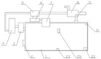
FIG. 1 is a schematic view of the overall structure of the present invention;
FIG. 2 is a schematic side view of a primary filter mechanism according to the present invention;
FIG. 3 is a schematic top view of the primary filter mechanism of the present invention;
FIG. 4 is a schematic view of the separating mechanism of the present invention;
FIG. 5 is a schematic view of the collection assembly of the present invention;
FIG. 6 is a schematic view of the structure at the absorbent mechanism of the present invention;
FIG. 7 is a schematic view of the heating mechanism of the present invention;
FIG. 8 is a schematic view of the operation of the collection module of the separation mechanism of the present invention.
Detailed Description
In order to make the objects, technical solutions and advantages of the embodiments of the present invention clearer, the technical solutions of the embodiments of the present invention will be clearly and completely described below with reference to fig. 1 to 8 of the embodiments of the present invention. It is to be understood that the embodiments described are only a few embodiments of the present invention, and not all embodiments. All other embodiments, which can be derived by a person skilled in the art from the described embodiments of the invention, are within the scope of the invention.
Example one
A high-efficiency purification device for a pig farm comprises a primary filtering mechanism 3 communicated with a pig house 1, a separating mechanism 4 communicated with the primary filtering mechanism 3, an absorbing mechanism 5 arranged at the rear part of the separating mechanism 4, a disinfecting mechanism 6 matched with the absorbing mechanism, a heating mechanism 7 matched with the disinfecting mechanism 6, a circulating pipe 10 connected with the absorbing mechanism, a preheating mechanism 8 arranged at the end part of the circulating pipe 10, an air inlet mechanism 9 arranged on the pig house 1 and matched with the preheating mechanism, and a control mechanism for controlling the primary filtering mechanism, the separating mechanism, the absorbing mechanism, the disinfecting mechanism, the heating mechanism, the preheating mechanism and the air inlet mechanism;
the primary filtering mechanism comprises an air outlet hole arranged on the pigsty 1, an air outlet pipe 301 arranged on the air outlet hole, a primary filtering bin 303 arranged on the air outlet pipe 301, a plurality of baffle plates 304 arranged on the side wall of the primary filtering bin, a collecting bin 309 arranged at the lower part of the primary filtering bin, a separation plate 315 arranged between the primary filtering bin 303 and the collecting bin 309, a linkage rod 310 arranged at the end part of the side edge of the separation plate 315, a steering wheel 316 arranged on the outer wall of the primary filtering bin 303, a filtering support rod 312 arranged on the inner wall of the air outlet pipe, a filtering sliding sleeve 313 arranged at the end part of the filtering support rod 312, a filtering sliding rod 311 arranged on the filtering sliding sleeve 313, a filtering wind plate 302 arranged at one end of the filtering sliding rod 311, a filtering spring 314 arranged on the filtering sliding rod 311 and matched with the filtering sliding sleeve 313, and a linkage rope 311 which is arranged on the filtering slide bar 311, passes through a hole on the air outlet pipe and bypasses a steering wheel and is connected with the linkage rod 310.
An ash deposition chamber 307 is arranged at the lower part of the collection bin, and a collection valve 308 is arranged between the collection bin and the ash deposition chamber.
The separating mechanism comprises a separating cylinder 401, a first separating pipe 305 arranged at the lower end of the separating cylinder 401 and communicated with the primary filtering bin, a second separating pipe 420 arranged at the lower end of the separating cylinder 401 and used for collecting liquid ammonia gas, a third separating pipe 419 arranged at the lower end of the separating cylinder 401 and used for exhausting gas, a separating support 423 arranged at the upper end of the separating cylinder 401, a separating slide cylinder 416 arranged on the separating support 423, a separating slide rod 415 arranged in the separating slide cylinder 416, a separating disc 417 arranged at the lower end of the separating slide rod 415, a compression sealing ring 418 arranged on the periphery side of the separating disc 417 and matched with the inner wall of the separating cylinder, and a collecting module arranged on the separating disc 417 and used for collecting liquid ammonia gas, and a separation telescopic rod 414 which is arranged on the separation supporting frame 423 and is matched with the separation sliding rod 415.
The collection module comprises a collection guide hole arranged on the separation disc 417, a collection sliding cylinder 424 arranged on the collection guide hole, a collection sliding rod 410 arranged in the collection sliding cylinder 424, a plurality of collection supporting rods 422 arranged at the lower end of the collection sliding rod 410, a collection ring 403 arranged at the end parts of the collection supporting rods 422, a collection assembly arranged on the periphery of the collection ring 403 and matched with the inner wall of the separation cylinder, a pulling ring 425 arranged on the separation disc 417, a collection pulling motor 405 arranged on the separation disc 417 and matched with the pulling ring 425, a winding wheel 406 arranged at the front end of the pulling motor 405, a collection rope 407 arranged on the winding wheel 406, and the starting end of the collection rope 407 bypasses the through hole at the upper end of the collection sliding rod 410 and is fixed with the pulling ring 425.
Collect the subassembly including setting up collect the ring 426 week side's elastic pressure ring, set up the sponge 402 that collects of elastic pressure ring lower surface, set up collect the water pipe 421 that collects in the sponge 402, collect the middle setting of slide bar 421 with collect water pipe 421 matched with collect pipe 409, set up collect the drainage tube 411 that collects of pipe 409 upper end exit end, it is linked together with the sump 413 that collects on the separation dish 417 to collect drainage tube 411, it sets up the solenoid valve and collects water pump 412 on the drainage tube to collect.
The absorption mechanism comprises an absorption tank 51, an absorption pipe 56 which is arranged on the absorption tank 51 and communicated with a third separation pipe 419, a plurality of auxiliary absorption pipes 54 which are arranged at the lower ends of the absorption pipes 56 and positioned at the bottom of the absorption tank 51, a plurality of absorption holes which are arranged on the auxiliary absorption pipes 54, a rotary joint 53 which is arranged on the absorption holes, an L-shaped air nozzle 55 which is arranged on the rotary joint 53, a collecting tank 52 which is arranged at the bottom 51 of the absorption tank, an absorption air outlet which is arranged at the upper end of the absorption tank 51 and a circulating pipe 10 which is arranged on the absorption air outlet.
The disinfection mechanism comprises two disinfection tubes 62 arranged on the absorption tank 51, a disinfection tank 61 arranged at the tail ends of the two disinfection tubes, a transduction tube 711 arranged at the bottom of the disinfection tank 61, and heat exchange fins 63 arranged on the transduction tube.
The heating mechanism comprises a heating support 701 arranged on the pigsty 1, a plurality of convex mirror heating modules arranged on the heating support 701, auxiliary heat exchange tubes 705 arranged on the heating support 701 and communicated with the energy exchange tubes 711, and four heating adjusting modules arranged on the heating support 701.
The convex mirror heating module comprises a heating cylinder 709, a first heating ring 707 arranged at the upper end of the heating cylinder 709, a convex mirror 708 arranged on the first heating ring 707, four ball heads 710 arranged at the circumference of the first heating ring 707 and uniformly distributed, a ball head seat 706 connected with the ball heads 710, and a heating support rod 704 arranged at the lower end of the ball head seat 706.
The four heating adjustment modules are arranged in a layered manner, and each heating adjustment module comprises a supporting cross rod 712 arranged at the lower part of a plurality of heating supporting rods 704, a transverse supporting rod 703 arranged at the end part of each supporting cross rod, and an adjusting telescopic arm 702 arranged at the lower part of the transverse supporting rod 703.
The preheating mechanism comprises a preheating pipe communicated with the circulating pipe, a plurality of preheating branch pipes 82 arranged at the rear parts of the preheating pipe and communicated with the preheating pipe, fins arranged on the preheating branch pipes 82, preheating outlet pipes 83 arranged at the rear parts of the preheating branch pipes 82, dustproof cotton 84 arranged on the preheating outlet pipes 83, the preheating branch pipes are arranged in a preheating bin 81, and purified water is arranged in the preheating bin.
Mechanism of admitting air sets up including setting up the inlet port on the pig house lateral wall intake pipe 95 on the inlet port, intake pipe 95 with preheating storehouse 81 upper end is connected, set up total intake pipe 91 on preheating storehouse 81, total intake pipe 91 immerses pure water lower part in the preheating storehouse and be linked together with a plurality of total air intake branch 92, set up a plurality ofly venthole on the total air intake branch, total intake pipe entry end sets up dustproof sponge 94, set up fan 93 in the total intake pipe 91.
Control mechanism includes computer 2, with computer 2 signal interconnection and the first temperature sensor 23 of setting in the pig house, the ammonia detector 21 of setting in the pig house sets up hydrogen sulfide detector 22 in the pig house sets up the second temperature sensor 24 of absorption tank inner wall sets up the photosensitive sensor 25 at pig house top, and with the commercial power that computer 2 is connected.
And the first separating pipe, the second separating pipe, the third separating pipe and the fourth separating pipe are all provided with electromagnetic valves.
The baffler that adopts in this embodiment is the hang plate to the slope of entry end slope for it forms the vortex in the contained angle department with the primary filter storehouse, and then makes granule dust here enrich, and after the air current disappears, makes the particulate matter fall into in the collection storehouse along with opening of division board, and when not carrying out the primary filter, collect can.
The adopted filtering spring is a rigid spring, certainly, an elastic rubber sleeve mode can be adopted, the separating telescopic rod and the adjusting telescopic arm are electric telescopic rods or hydraulic telescopic rods, certainly, a hydraulic telescopic rod mode can be adopted, the adopted collecting traction motor is a stepping motor, certainly, a common small motor can be adopted, and as the required pressure is not very high, the adopted compression sealing ring is an O-shaped sealing ring or a graphite sealing ring, in addition, the optimized annular conical surface matched with the collecting sponge is arranged at the bottom of the separating tank, so that the solution on the collecting sponge can be extruded during extrusion, the solution is collected at the lower second separating pipe and then enters the pressure tank, and can be extruded after being collected for many times, thereby obtaining the ammonia solution with higher concentration, and the collecting mode can also enable germs to survive in an environment with higher pressure, and then suddenly reduces the pressure when entering the absorption mechanism, thereby being more beneficial to quickly killing germs.
In addition, the adoption of the ball head support mode can ensure the arbitrariness when the angle is adjusted, and certainly, the connection can be carried out in a universal joint mode, and even in an elastic rubber column mode, the angle can be adjusted.
Example two
The difference from the first embodiment is that: the lower end of the second separation pipe is connected with a pressure tank 427, a fourth separation pipe 428 arranged at the lower part of the pressure tank 427, and a liquid storage tank 429 arranged at the lower part of the fourth separation pipe.
By adopting a two-stage separation mode, high-concentration ammonia water solution can be extracted, and the water consumed by absorbing ammonia gas is reduced.
EXAMPLE III
The difference from the second embodiment is that: the low-concentration acetic acid is arranged in the collecting sponge, so that ammonia gas can be repeatedly removed by using a small amount of acetic acid, the removing effect is ensured, and the phenomenon that the using amount of the absorption liquid is greatly consumed due to the influence of pathogenic bacteria is reduced.
While the foregoing is directed to the preferred embodiment of the present invention, it will be understood by those skilled in the art that various changes and modifications may be made without departing from the spirit and scope of the invention as defined in the appended claims.
Claims (9)
1. The utility model provides a high-efficient purifier in pig farm which characterized in that: the device comprises a primary filtering mechanism communicated with a pigsty, a separating mechanism communicated with the primary filtering mechanism, an absorbing mechanism arranged at the rear part of the separating mechanism, a sterilizing mechanism matched with the absorbing mechanism, a heating mechanism matched with the sterilizing mechanism, a circulating pipe connected with the absorbing mechanism, a preheating mechanism communicated with the absorbing mechanism through the circulating pipe, an air inlet mechanism arranged on the pigsty and matched with the preheating mechanism, and a control mechanism used for controlling the primary filtering mechanism, the separating mechanism, the absorbing mechanism, the sterilizing mechanism, the heating mechanism, the preheating mechanism and the air inlet mechanism;
the primary filtering mechanism comprises an air outlet hole arranged on the pigsty, an air outlet pipe arranged on the air outlet hole, a primary filtering bin arranged on the air outlet pipe, a plurality of baffle plates arranged on the side wall of the primary filtering bin, a collecting bin arranged at the lower part of the primary filtering bin, and a baffle plate arranged between the primary filtering bin and the collecting bin, the division board side tip sets up the gangbar, sets up directive wheel on the primary filter storehouse outer wall sets up filtration bracing piece on the outlet duct inner wall sets up the filtration sliding sleeve of filtration bracing piece tip sets up filtration slide bar on the filtration sliding sleeve sets up the filtration aerofoil of filtration slide bar one end sets up on the filtration slide bar and with filtration sliding sleeve matched with filters the spring, sets up bypass the directive wheel on the filtration slide bar with the linkage rope that the gangbar is connected.
2. The efficient purification device of pig farm according to claim 1, characterized in that: separating mechanism includes the cylinder, sets up the cylinder lower extreme and with the first separator tube that the one-level filter storehouse is linked together sets up the second separator tube that the cylinder lower extreme is used for collecting liquid ammonia sets up the third separator tube that the cylinder lower extreme is used for getting rid of gas sets up the separation support frame of cylinder upper end sets up the separation slide cartridge on the separation support frame, sets up separation slide bar in the separation slide cartridge sets up the separation disc of separation slide bar lower extreme sets up separation disc week side and with cylinder inner wall matched with compression seal circle sets up the module that collects liquid ammonia on the separation disc, and sets up on the separation support frame and with separation slide bar matched with separation telescopic link.
3. The efficient purification apparatus for pig farms of claim 2, characterized in that: collect the module including setting up collect the guiding hole on the separation disc, set up collect the slide cartridge that collects on the guiding hole, set up collect the slide bar that collects in the slide cartridge, set up collect many of slide bar end lower extreme and collect the bracing piece, set up many collect the ring that collects the bracing piece tip, set up collect ring week side and with separation cylinder inner wall matched with collects the subassembly, set up and be in draw ring on the separation disc sets up on the separation disc and with draw ring matched with collects the traction motor, sets up the wind-up wheel of traction motor front end sets up collect the rope on the wind-up wheel, the initiating terminal that collects the rope is walked around and is collected the through-hole of slide bar upper end and fixed mutually with draw ring.
4. The efficient purification apparatus for pig farms of claim 3, characterized in that: absorption mechanism includes the absorption tank, sets up the absorption tube that just is linked together with the third separation pipe on the absorption tank sets up many supplementary absorption tubes that absorption tube lower extreme just is located the absorption tank bottom set up a plurality of absorption holes on the supplementary absorption tube set up rotary joint on the absorption hole sets up L type air nozzle on the rotary joint sets up the collecting vat of absorption tank bottom, and set up and be in the absorption venthole of absorption tank upper end sets up circulating pipe on the absorption venthole.
5. The efficient purification device of pig farm according to claim 4, characterized in that: the heating mechanism is in including setting up the heating support on the pig house, setting a plurality of convex mirror heating module on the heating support, set up on the heating support and with the supplementary heat exchange tube that the transduction pipe is linked together sets up four heating adjustment modules on the heating support.
6. The efficient purification device of pig farm according to claim 5, characterized in that: the convex mirror heating module comprises a heating cylinder, a first heating ring arranged at the upper end of the heating cylinder, a convex mirror arranged on the first heating ring, four ball heads which are arranged on the circumference of the first heating ring and are uniformly distributed, a ball head seat connected with the ball heads, and a heating support rod arranged at the lower end of the ball head seat;
four heating adjustment module layering sets up, heating adjustment module is including setting up at a plurality of heating support rod lower parts's support horizontal pole, sets up a plurality of support horizontal pole tip horizontal bracing piece sets up the flexible arm of regulation of horizontal bracing piece lower part.
7. The efficient purification device of pig farm of claim 6, characterized in that: the preheating mechanism comprises a preheating pipe communicated with the circulating pipe, a plurality of preheating branch pipes arranged at the rear part of the preheating pipe and communicated with the preheating pipe, fins arranged on the preheating branch pipes, preheating outlet pipes arranged at the rear parts of the preheating branch pipes, dustproof cotton arranged on the preheating outlet pipes, the preheating branch pipes are arranged in the preheating bin, and purified water is arranged in the preheating bin.
8. The efficient purification apparatus for pig farms of claim 7, characterized in that: the mechanism of admitting air sets up including setting up the inlet port on the pig house lateral wall intake pipe on the inlet port, the intake pipe with preheat the storehouse upper end and be connected, set up total intake pipe on the storehouse of preheating, total intake pipe immerses pure water lower part in the storehouse of preheating and be linked together with a plurality of total air inlet branch pipe, set up a plurality of venthole on the total air inlet branch pipe, total intake pipe entry end sets up dustproof sponge, set up the fan in the total intake pipe.
9. The efficient purification apparatus for pig farms of claim 8, characterized in that: control mechanism includes the computer, with computer signal interconnection and the first temperature sensor who sets up in the pig house, the ammonia detector of setting in the pig house set up hydrogen sulfide detector in the pig house sets up the second temperature sensor of tourism inner wall sets up the photosensitive sensor at pig house top, and with the commercial power that the computer is connected.
Priority Applications (1)
| Application Number | Priority Date | Filing Date | Title |
|---|---|---|---|
| CN201811419969.7A CN111214920B (en) | 2018-11-26 | 2018-11-26 | High-efficient purifier in pig farm |
Applications Claiming Priority (1)
| Application Number | Priority Date | Filing Date | Title |
|---|---|---|---|
| CN201811419969.7A CN111214920B (en) | 2018-11-26 | 2018-11-26 | High-efficient purifier in pig farm |
Publications (2)
| Publication Number | Publication Date |
|---|---|
| CN111214920A true CN111214920A (en) | 2020-06-02 |
| CN111214920B CN111214920B (en) | 2022-08-09 |
Family
ID=70805670
Family Applications (1)
| Application Number | Title | Priority Date | Filing Date |
|---|---|---|---|
| CN201811419969.7A Active CN111214920B (en) | 2018-11-26 | 2018-11-26 | High-efficient purifier in pig farm |
Country Status (1)
| Country | Link |
|---|---|
| CN (1) | CN111214920B (en) |
Cited By (1)
| Publication number | Priority date | Publication date | Assignee | Title |
|---|---|---|---|---|
| CN109663453A (en) * | 2019-03-15 | 2019-04-23 | 广东德兴食品股份有限公司 | A kind of high-level cleaner on pig farm |
Citations (17)
| Publication number | Priority date | Publication date | Assignee | Title |
|---|---|---|---|---|
| DE3310595A1 (en) * | 1983-03-23 | 1984-09-27 | Helmut Dipl.-agr.-Ing. 7407 Rottenburg Bugl | Arrangement for keeping livestock, such as pigs, cows, poultry, rabbits, and livestock-receiving container for use in this arrangement |
| US5738834A (en) * | 1996-09-09 | 1998-04-14 | Gas Research Institute | System for removal of hydrogen sulfide from a gas stream |
| CN1257186A (en) * | 1998-10-19 | 2000-06-21 | 梁军 | All-weather large-power solar-energy electricity-generating system |
| US7371328B1 (en) * | 2001-09-26 | 2008-05-13 | Recovery Systems, Inc. | Method for treating hog and animal waste |
| US20120180658A1 (en) * | 2009-07-22 | 2012-07-19 | Willibrordus Nicolaas Johannes Ursem | Method for the removal of a gaseous fluid and arrangement therefore |
| CN102641657A (en) * | 2011-02-18 | 2012-08-22 | 上海离岛电子新材料有限公司 | Method for strictly controlling discharge of ammonia-containing tail gas in the ammonium salt production and improving ammonium salt output using the tail gas |
| CN203860197U (en) * | 2014-03-21 | 2014-10-08 | 玉林市大和养猪专业合作社 | Sow house with temperature capable of being adjusted and controlled |
| CN204426252U (en) * | 2014-12-31 | 2015-07-01 | 广东德兴种养实业有限公司 | A kind of closed pig house auto-admission device |
| CN105475164A (en) * | 2016-01-20 | 2016-04-13 | 惠州莫思特科技有限公司 | Multifunctional duck feeding farm |
| CN106076042A (en) * | 2016-08-16 | 2016-11-09 | 中电建水环境治理技术有限公司 | Bed mud carbonization potting tail gas multistage purification processing system is gushed in lake, river |
| CN107135978A (en) * | 2017-06-29 | 2017-09-08 | 重庆市万源禽蛋食品有限公司 | Fowl house taste removal system and deodorizing method and application |
| CN107376559A (en) * | 2017-07-27 | 2017-11-24 | 国网河南省电力公司西峡县供电公司 | A kind of discarded cable high-temperature processing unit waste gas Online Processing System |
| CN107472992A (en) * | 2017-08-13 | 2017-12-15 | 裴天锋 | A kind of waste and old cable material separating and reclaiming device |
| CN108144386A (en) * | 2018-02-05 | 2018-06-12 | 邱榕生 | A kind of method of poultry house air multistage cleaning deodorization |
| CN108218489A (en) * | 2017-12-31 | 2018-06-29 | 邵真 | A kind of organic fertilizer fermentation device using clean energy resource |
| CN108404539A (en) * | 2018-04-20 | 2018-08-17 | 成都奕州环保科技有限公司 | A kind of bag filter |
| CN108633748A (en) * | 2018-06-26 | 2018-10-12 | 广东益康生环保设备有限公司 | Breeding house end foul smell prevention and control system and method |
-
2018
- 2018-11-26 CN CN201811419969.7A patent/CN111214920B/en active Active
Patent Citations (17)
| Publication number | Priority date | Publication date | Assignee | Title |
|---|---|---|---|---|
| DE3310595A1 (en) * | 1983-03-23 | 1984-09-27 | Helmut Dipl.-agr.-Ing. 7407 Rottenburg Bugl | Arrangement for keeping livestock, such as pigs, cows, poultry, rabbits, and livestock-receiving container for use in this arrangement |
| US5738834A (en) * | 1996-09-09 | 1998-04-14 | Gas Research Institute | System for removal of hydrogen sulfide from a gas stream |
| CN1257186A (en) * | 1998-10-19 | 2000-06-21 | 梁军 | All-weather large-power solar-energy electricity-generating system |
| US7371328B1 (en) * | 2001-09-26 | 2008-05-13 | Recovery Systems, Inc. | Method for treating hog and animal waste |
| US20120180658A1 (en) * | 2009-07-22 | 2012-07-19 | Willibrordus Nicolaas Johannes Ursem | Method for the removal of a gaseous fluid and arrangement therefore |
| CN102641657A (en) * | 2011-02-18 | 2012-08-22 | 上海离岛电子新材料有限公司 | Method for strictly controlling discharge of ammonia-containing tail gas in the ammonium salt production and improving ammonium salt output using the tail gas |
| CN203860197U (en) * | 2014-03-21 | 2014-10-08 | 玉林市大和养猪专业合作社 | Sow house with temperature capable of being adjusted and controlled |
| CN204426252U (en) * | 2014-12-31 | 2015-07-01 | 广东德兴种养实业有限公司 | A kind of closed pig house auto-admission device |
| CN105475164A (en) * | 2016-01-20 | 2016-04-13 | 惠州莫思特科技有限公司 | Multifunctional duck feeding farm |
| CN106076042A (en) * | 2016-08-16 | 2016-11-09 | 中电建水环境治理技术有限公司 | Bed mud carbonization potting tail gas multistage purification processing system is gushed in lake, river |
| CN107135978A (en) * | 2017-06-29 | 2017-09-08 | 重庆市万源禽蛋食品有限公司 | Fowl house taste removal system and deodorizing method and application |
| CN107376559A (en) * | 2017-07-27 | 2017-11-24 | 国网河南省电力公司西峡县供电公司 | A kind of discarded cable high-temperature processing unit waste gas Online Processing System |
| CN107472992A (en) * | 2017-08-13 | 2017-12-15 | 裴天锋 | A kind of waste and old cable material separating and reclaiming device |
| CN108218489A (en) * | 2017-12-31 | 2018-06-29 | 邵真 | A kind of organic fertilizer fermentation device using clean energy resource |
| CN108144386A (en) * | 2018-02-05 | 2018-06-12 | 邱榕生 | A kind of method of poultry house air multistage cleaning deodorization |
| CN108404539A (en) * | 2018-04-20 | 2018-08-17 | 成都奕州环保科技有限公司 | A kind of bag filter |
| CN108633748A (en) * | 2018-06-26 | 2018-10-12 | 广东益康生环保设备有限公司 | Breeding house end foul smell prevention and control system and method |
Non-Patent Citations (3)
| Title |
|---|
| 段彦平: "冬季猪舍小环境的调控", 《北方牧业》 * |
| 王鹏鹏等: "猪舍有害气体检测与控制方法的研究现状", 《黑龙江畜牧兽医》 * |
| 琚学慧: "规模化养猪场应重点注意的问题", 《现代农业科技》 * |
Cited By (1)
| Publication number | Priority date | Publication date | Assignee | Title |
|---|---|---|---|---|
| CN109663453A (en) * | 2019-03-15 | 2019-04-23 | 广东德兴食品股份有限公司 | A kind of high-level cleaner on pig farm |
Also Published As
| Publication number | Publication date |
|---|---|
| CN111214920B (en) | 2022-08-09 |
Similar Documents
| Publication | Publication Date | Title |
|---|---|---|
| CN106082533B (en) | Landscape fishpond purification treatment system and treatment method | |
| CN105735416A (en) | Remotely controllable air purification water maker | |
| CN209475975U (en) | A kind of waste-gas heat recycling deodorization device | |
| CN103845754A (en) | Sterilization and disinfection purification device and method for air in livestock shed | |
| CN203898789U (en) | Sterilization, disinfection and purification device for air in livestock breeding shed | |
| CN104296258A (en) | Indoor air purifier and indoor air purifying method based on same | |
| CN111214920B (en) | High-efficient purifier in pig farm | |
| CN105928089A (en) | Desktop air purifier | |
| CN208490526U (en) | A kind of poultry house ventilating deodorizing device | |
| CN208660753U (en) | A kind of farm's foul gas processing unit | |
| CN205596824U (en) | Aquaculture is with multistage exhaust deodorizing device | |
| CN214250018U (en) | But self-adjusting formula clarifier of real-time supervision indoor environment | |
| CN205694854U (en) | A kind of multistage aerofluxus odor removal for poultry house | |
| CN212283377U (en) | Waste gas purification treatment device | |
| CN211004929U (en) | Water treatment sterilizing device | |
| CN113636698A (en) | Sewage treatment system based on full-automatic microstrainer | |
| CN213388042U (en) | Energy-saving sewage treatment device for livestock breeding | |
| CN205843003U (en) | A kind of room fresh air Intelligent purifying system | |
| CN211793598U (en) | Longitudinal flow guide device of transverse negative pressure fan ventilation system and pigsty with longitudinal flow guide device | |
| CN109663453A (en) | A kind of high-level cleaner on pig farm | |
| CN204165150U (en) | Indoor air cleaner | |
| CN213454094U (en) | ICU ward air cycle degassing unit | |
| CN216837514U (en) | Circulating water tank for deodorization and sterilization | |
| CN212174649U (en) | Water resource recycling device for animal husbandry | |
| CN220023809U (en) | Multifunctional yak breeding house |
Legal Events
| Date | Code | Title | Description |
|---|---|---|---|
| PB01 | Publication | ||
| PB01 | Publication | ||
| SE01 | Entry into force of request for substantive examination | ||
| SE01 | Entry into force of request for substantive examination | ||
| GR01 | Patent grant | ||
| GR01 | Patent grant |