Disclosure of Invention
The invention aims to provide a battery box which adopts an external circulation heat dissipation structure so as to solve the technical problems of insufficient heat dissipation and shortened service life of a battery of the conventional battery box.
In order to achieve the purpose, the invention provides the following technical scheme:
a battery box comprises a box body and a box cover arranged at the top end of the box body; a first opening is formed in one side face of the box body, a fan fixing frame for fixing a turbofan is arranged on the outer side face of the first opening, and the turbofan is fixed in the fan fixing frame; a second opening is formed in the other side face of the box body, and a shutter is arranged on the outer side face of the second opening; the first opening and the second opening are arranged oppositely, and the distance between the first opening and the box cover is smaller than the distance between the second opening and the box cover.
In order to enable the battery to be sufficiently cooled after external cold air enters the box body, the first opening and the second opening are asymmetrically arranged, and the distance between the first opening and the box cover is smaller than the distance between the second opening and the box cover. And cold air enters the box body from a second opening positioned at a low position, cools the battery from bottom to top and then is discharged from the turbofan at the first opening positioned at a high position.
Further, the turbofan comprises an air cavity, an air outlet channel, a first air inlet and a turbofan;
the air cavity is a cylindrical shell which is arranged in a hollow mode;
the air outlet channel extends outwards from the arc-shaped side surface of the shell along the tangential direction and is communicated with the air cavity;
the first air inlet is a round hole arranged on the round bottom surface of the air cavity, and the first air inlet and the air cavity are eccentrically arranged to gradually increase the cross-sectional area of a channel formed by the periphery of the turbofan and the inner wall of the air cavity;
and the turbofan is arranged in the air cavity and is concentrically arranged with the first air inlet.
Furthermore, a plurality of first through holes are arranged on the outer side of the air cavity, the first through holes are arranged in a triangular mode, and the air cavity and the first through holes are integrally formed.
Furthermore, the fan fixing frame comprises a fixing plate which is vertically arranged, two first positioning plates which are oppositely arranged, and second positioning plates which are respectively arranged at two ends of the first positioning plates and connected with the two first positioning plates; the two first positioning plates are oppositely arranged at the left side and the right side of the fixed plate, and the two second positioning plates are oppositely arranged at the upper side and the lower side of the fixed plate; the two first positioning plates and the two second positioning plates are respectively fixed on the outer side surface of the first opening.
Further, the second locating plate includes locating plate under second top management plate and the second, be provided with a plurality of square notches that are used for fixing turbofan's air-out passageway on the locating plate under the second, square notch with air-out passageway interference fit.
Furthermore, a plurality of studs matched with the first through holes are arranged on the inner side surface of the fixing plate.
The stud penetrates through the first through hole and is fixedly connected with the nut to fix the turbofan on the fan fixing frame, so that a triangular stable structure with three points fixed is formed. Through setting up double-screw bolt and square notch, can effectively fix turbofan.
Furthermore, a plurality of second air inlets are uniformly formed in the louver. When the turbofan works, hot air inside the battery box is discharged outside the battery box through the turbofan air outlet channel, and due to the atmospheric pressure principle, cold air outside the battery box can enter the battery box through the second air inlet of the louver, so that exchange of air inside and outside the battery box is realized, and the purpose of circulating heat dissipation is achieved.
Furthermore, a baffle is arranged on the second air inlet. Prevent impurities such as dust in the air from falling into the battery box and causing damage to the battery, and prolong the service life of the battery.
Furthermore, two sides of the box body are respectively and symmetrically provided with one or more handles, so that the box body can be conveniently moved and lifted.
Furthermore, two turbofan are arranged in the fan fixing frame. By arranging two turbofan, the heat radiation efficiency can be accelerated.
Further, the area of the second opening is 50% -70% of the area of the side face of the box body where the second opening is located, and 70% is preferable. Therefore, the internal and external airflow exchange can be accelerated well, and the stability of the whole structure of the battery box is not influenced.
Compared with the prior art, the invention has the following beneficial effects:
the invention adopts an external circulation heat radiation mode, and the external circulation heat radiation device is arranged, so that the circulation of cold and hot air in the battery box can be accelerated well, the battery box has good cooling effect, the problems of overhigh temperature, untimely heat radiation and the like in the battery box can be solved effectively, the potential safety hazard is eliminated, the cycle life of the battery is prolonged effectively, and the consistency of the battery capacity can be ensured better. The invention has the advantages of simple structure, convenient installation, better stability, economy and practicality.
Detailed Description
The present invention will be described in further detail with reference to examples, but the embodiments of the present invention are not limited thereto.
The technical solutions in the embodiments of the present invention will be clearly and completely described below with reference to the drawings in the embodiments of the present invention, and it is obvious that the described embodiments are only a part of the embodiments of the present invention, and not all of the embodiments. All other embodiments, which can be derived by a person skilled in the art from the embodiments given herein without making any creative effort, shall fall within the protection scope of the present invention.
It should be noted that, if directional indications (such as up, down, left, right, front, back, top and bottom … …) are involved in the embodiment of the present invention, the directional indications are only used to explain the relative position relationship between the components, the motion situation, etc. in a specific posture (as shown in the drawing), and if the specific posture is changed, the directional indications are changed accordingly.
In addition, if there is a description of "first", "second", etc. in an embodiment of the present invention, the description of "first", "second", etc. is for descriptive purposes only and is not to be construed as indicating or implying relative importance or implicitly indicating the number of technical features indicated. Thus, a feature defined as "first" or "second" may explicitly or implicitly include at least one such feature. In addition, technical solutions between various embodiments may be combined with each other, but must be realized by a person skilled in the art, and when the technical solutions are contradictory or cannot be realized, such a combination should not be considered to exist, and is not within the protection scope of the present invention.
The battery boxes on the market are generally sealed and installed, the fans are mainly used for circularly utilizing heat transfer of the battery boxes by virtue of internal air in the boxes and dissipating the heat into the ambient air, the heat dissipation effect is poor, the generated heat is uneven, batteries close to the four walls of the battery boxes can transfer the heat to the box walls by virtue of sheet metal parts and dissipate the heat into the ambient air outside the battery boxes by virtue of the box walls, the heat is difficult to transfer to the four walls by virtue of a middle battery cell due to the distance, and the heat can be gathered in the middle of the battery box without being dissipated, so that the performance of the battery is influenced; the temperature in the battery box is too low, so that the cycle life of the battery is prolonged, and the consistency of the battery capacity can be better guaranteed; the battery temperature is too high, and certain potential safety hazard can exist.
At present, the battery box with the waterproof grade above IP67 is required to adopt an internal circulation heat dissipation structure, the external full-sealed assembly is adopted, the heat dissipation is completely realized by air inside the battery box, the space inside the battery box is limited and cannot be communicated with the outside air, so that hot air inside the battery box cannot be discharged out of the box, the heat dissipation is mainly realized by a natural cooling mode of the battery box and the inside air, and the heat dissipation effect is very unsatisfactory. For the battery box with the waterproof grade below IP54 or low waterproof requirement, an external circulation heat dissipation mode can be adopted for heat dissipation, and the heat dissipation effect is improved.
This application is provided with two turbofan and great second air intake, air outlet, and the outflow of the inside air of acceleration battery box that can be fine to accelerate the circulation of the cold hot air flow in the battery box, and then accelerate the inflow of the cold air in the battery box and the outflow of hot-air, have good cooling effect.
As shown in fig. 1-3, a battery box includes a box body 1 and a box cover 2 disposed at the top end of the box body 1, wherein the box body 1 and the box cover 2 are hermetically connected by a first screw 3; a first opening 11 is formed in one side face of the box body 1, a fan fixing frame 5 for fixing a turbofan 4 is arranged on the outer side face of the first opening 11, and the turbofan 4 is fixed in the fan fixing frame 5; a second opening 12 is arranged on the other side surface of the box body 1, and a shutter 6 is arranged on the outer side surface of the second opening 12; the first opening 11 and the second opening 12 are disposed opposite to each other, and a distance between the first opening 11 and the case cover 2 is smaller than a distance between the second opening 12 and the case cover 2.
In order to sufficiently cool the battery after the external cold air enters the box body 1, the first opening 11 and the second opening 12 are asymmetrically arranged, and the distance between the first opening 11 and the box cover 2 is smaller than the distance between the second opening 12 and the box cover 2. The cold air enters the case 1 through the second opening 12 located at a lower position, cools the battery from bottom to top, and is discharged from the turbofan 3 at the first opening 11 located at a higher position.
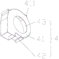
As shown in fig. 4, in the present embodiment, the turbofan 4 includes an air chamber 41, an air outlet channel 42, a first air inlet 43, and a turbofan (not shown); the air cavity 41 is a hollow cylindrical shell; the air outlet channel 42 extends outwards from the arc-shaped side surface of the shell of the air cavity 41 along the tangential direction and is communicated with the air cavity 41; the first air inlet 43 is a circular hole arranged on the circular bottom surface of the air cavity 31, and the first air inlet 43 and the air cavity 41 are eccentrically arranged to gradually increase the cross-sectional area of a channel formed by the periphery of the turbofan and the inner wall of the air cavity; the turbofan is disposed in the air chamber 41 and is concentric with the first air inlet 43.
Further, in this embodiment, the outside of the air cavity 41 is provided with a plurality of first through holes 411, and the plurality of first through holes 411 are arranged in a triangular manner, and the air cavity 41 and the plurality of first through holes 411 are integrally formed.
Referring to fig. 1 again, in the present embodiment, the fan fixing frame 5 includes a fixing plate 51 vertically disposed, two first positioning plates 52 disposed opposite to each other, and second positioning plates 53 respectively disposed at two ends of the first positioning plates 52 and connected to the two first positioning plates 52; the two first positioning plates 52 are oppositely arranged at the left side and the right side of the fixed plate 51, and the two second positioning plates 53 are oppositely arranged at the upper side and the lower side of the fixed plate 51; the two first positioning plates 52 and the two second positioning plates 53 are respectively fixed on the outer side surface of the first opening 11.
Further, in the present embodiment, the second positioning plate 53 includes a second upper positioning plate 531 and a second lower positioning plate 532, a plurality of square notches 532a for fixing the air outlet channel 42 of the turbofan 4 are disposed on the second lower positioning plate 532, and the square notches 532a are in interference fit with the air outlet channel 42.
Specifically, in this embodiment, a plurality of studs 511 matching with the first through holes 411 are disposed on the inner side surface of the fixing plate 51. The stud 511 passes through the first through hole 411 and is locked with a nut (not shown) to fix the turbofan 4 on the fan fixing plate 5, so as to form a triangular stable structure with three fixed points. By providing the stud 511 and the square notch 532a, the turbofan 4 can be effectively fixed.
Referring to fig. 3 again, in the present embodiment, a plurality of second air inlets 61 are uniformly formed on the louver 6. When the turbofan 4 works, the hot air inside the battery box is discharged outside the battery box through the air outlet channel 42 of the turbofan 4, and due to the atmospheric pressure principle, the cold air outside the battery box enters the battery box through the second air inlet 61 of the shutter 6, so that the exchange of the air inside and outside the battery box is realized, and the purpose of circulating heat dissipation is achieved.
Further, in this embodiment, the second air inlet 61 is provided with a baffle 62. The baffle plate 62 can prevent impurities in the air such as dust from falling into the battery box to damage the battery, thereby effectively prolonging the service life of the battery.
Generally, the fan fixing frame 5 and the box 1, and the louver 6 and the box 1 may be fixedly connected by screws, nuts, or screws. Specifically, in this embodiment, the fan fixing frame 5 and the box body 1, and the louver 6 and the box body 1 are connected and fixed through a plurality of second screws 7 circumferentially arranged.
Further, in this embodiment, two handles 13 are symmetrically disposed on two sides of the box body 1, so that the box body can be moved and lifted conveniently.
In the present embodiment, two turbo fans 4 are disposed in the fan fixing frame 5. Through setting up two turbofan 4, can effectual quickening heat dissipation, improve the radiating efficiency.
Generally, the area of the second opening 12 is 50% -70% of the area of the side surface of the box body 1 where the second opening 12 is located. Specifically, in this embodiment, the area of the second opening 12 is 70% of the area of the side surface of the box body 1 where the second opening 12 is located. It is understood that in other embodiments, the area of the second opening 12 is any value of 50% to 70% of the area of the side surface of the box body 1 where the second opening 12 is located, for example, the area of the second opening 12 may be 50%, 60% or 65% of the area of the side surface of the box body 1 where the second opening 12 is located according to actual needs, which may well accelerate the exchange of the internal air and the external air and does not affect the overall structural stability of the battery box.
The working principle is as follows: when the power supply is switched on, the turbofan starts to work, hot air in the battery box is exhausted from the box body through the air outlet channel, the air pressure in the box body is reduced, cold air outside the battery box flows into the box body from the second air inlet (large) due to the pressure principle, the cold air flows to the first air inlet of the turbofan in the process of completely cooling the batteries in the battery box, becomes hot air after being cooled, and is finally blown out through the turbofan, so that the external circulation heat dissipation of the battery box is realized.
According to the invention, the external circulation heat dissipation device is arranged, hot air in the battery box is exhausted from the box body through the air outlet channel, the air pressure in the box body is reduced, cold air outside the battery box flows into the box body from the second air inlet due to the pressure principle, the batteries in the battery box are completely cooled in the process of flowing to the first air inlet of the turbofan, the cooled cold air is changed into hot air, and finally the hot air is blown out through the turbofan. The invention can effectively solve the problems of overhigh temperature, untimely heat dissipation and the like in the battery box, eliminates potential safety hazards, effectively prolongs the cycle life of the battery and can better ensure the consistency of the battery capacity.
The above embodiments are preferred embodiments of the present invention, but the present invention is not limited to the above embodiments, and any other changes, modifications, substitutions, combinations, and simplifications which do not depart from the spirit and principle of the present invention should be construed as equivalents thereof, and all such changes, modifications, substitutions, combinations, and simplifications are intended to be included in the scope of the present invention.