CN111155155B - Universal type groove external electroplating system for cylinder body - Google Patents
Universal type groove external electroplating system for cylinder body Download PDFInfo
- Publication number
- CN111155155B CN111155155B CN201911244524.4A CN201911244524A CN111155155B CN 111155155 B CN111155155 B CN 111155155B CN 201911244524 A CN201911244524 A CN 201911244524A CN 111155155 B CN111155155 B CN 111155155B
- Authority
- CN
- China
- Prior art keywords
- liquid
- electroplating
- workpiece
- assembly
- flow guide
- Prior art date
- Legal status (The legal status is an assumption and is not a legal conclusion. Google has not performed a legal analysis and makes no representation as to the accuracy of the status listed.)
- Active
Links
Images



Classifications
-
- C—CHEMISTRY; METALLURGY
- C25—ELECTROLYTIC OR ELECTROPHORETIC PROCESSES; APPARATUS THEREFOR
- C25D—PROCESSES FOR THE ELECTROLYTIC OR ELECTROPHORETIC PRODUCTION OF COATINGS; ELECTROFORMING; APPARATUS THEREFOR
- C25D7/00—Electroplating characterised by the article coated
- C25D7/04—Tubes; Rings; Hollow bodies
-
- C—CHEMISTRY; METALLURGY
- C25—ELECTROLYTIC OR ELECTROPHORETIC PROCESSES; APPARATUS THEREFOR
- C25D—PROCESSES FOR THE ELECTROLYTIC OR ELECTROPHORETIC PRODUCTION OF COATINGS; ELECTROFORMING; APPARATUS THEREFOR
- C25D17/00—Constructional parts, or assemblies thereof, of cells for electrolytic coating
- C25D17/06—Suspending or supporting devices for articles to be coated
-
- C—CHEMISTRY; METALLURGY
- C25—ELECTROLYTIC OR ELECTROPHORETIC PROCESSES; APPARATUS THEREFOR
- C25D—PROCESSES FOR THE ELECTROLYTIC OR ELECTROPHORETIC PRODUCTION OF COATINGS; ELECTROFORMING; APPARATUS THEREFOR
- C25D5/00—Electroplating characterised by the process; Pretreatment or after-treatment of workpieces
- C25D5/34—Pretreatment of metallic surfaces to be electroplated
Landscapes
- Chemical & Material Sciences (AREA)
- Engineering & Computer Science (AREA)
- Chemical Kinetics & Catalysis (AREA)
- Electrochemistry (AREA)
- Materials Engineering (AREA)
- Metallurgy (AREA)
- Organic Chemistry (AREA)
- Electroplating Methods And Accessories (AREA)
Abstract
The invention discloses a general type external groove electroplating system for a cylinder body, which comprises a pre-plating treatment device, an electroplating device and a general type tool; the universal tool comprises a mounting frame assembly and an installation auxiliary assembly, wherein the mounting frame assembly comprises a fixing frame and a pressing assembly; the fixing frame comprises a bottom plate and a frame fixed on the bottom plate; the installation auxiliary assembly is used for installing a workpiece, compensating the height and the diameter of the workpiece, installing the workpiece on the bottom plate and compressing the workpiece through the compressing assembly, and is also used for introducing pretreatment liquid into the cylinder body to form a pretreatment environment in a pretreatment plating process, introducing electroplating liquid into the cylinder body in an electroplating process and forming an electroplating environment between the anode and the workpiece through the anode; the invention is suitable for workpieces with various sizes in the electroplating pretreatment process and the electroplating process, realizes seamless switching of products, avoids capacity loss caused by line stop, quickly meets delivery requirements, minimizes switching time of mature products, and minimizes capacity loss.
Description
Technical Field
The invention relates to a component of a cylinder body electroplating device, in particular to a general type groove external electroplating system for a cylinder body.
Background
The cylinder body is used as a main part of equipment such as an engine, a plunger pump, a reciprocating compressor and the like and is used for forming a working space together with the piston and the cylinder head; taking an engine as an example, the engine forms a combustion chamber and provides a motion track for the piston assembly, so that a power conversion environment is formed. In the process of guiding the piston to continuously reciprocate, the inner wall of the cylinder and the piston rub against each other for a long time at a high frequency, so that the useful power of the cylinder is reduced, and a part of energy is consumed. In order to solve the problems, electroplating is carried out on the inner wall, and an electroplating coating is used for replacing the cylinder sleeve to solve the problems. In the prior art, the circulating electroplating outside the tank ensures that cations on a plating layer are replaced in real time due to the formation of a flowing electroplating environment, the concentration of the plating layer is not different, the fluidity of the plating layer is stable and uniform, the compactness of the plating layer is ensured, and the electroplating quality is ensured.
However, in the existing structure for plating outside the bath, because the external dimensions of the cylinder body (workpiece) are different, the false anode needs to be replaced in the pre-plating treatment process, the anode (especially the height) needs to be replaced in the plating process for the normal operation of the plating work, the whole production line needs to be stopped, the loss is increased, and the production cost is increased; and frock clamp is also diverse, and the structure is complicated, and the change process needs the manual work to go on, reduces work efficiency.
Therefore, the existing tooling for circular electroplating needs to be improved, the tooling has universality, the pre-electroplating treatment process and the electroplating process are suitable for workpieces with various sizes, seamless switching of products is realized, the capacity loss caused by line stop is avoided, the delivery demand is quickly met, the switching time of mature products is reduced to the minimum, and the capacity loss is reduced to the minimum.
Disclosure of Invention
In view of the above, an object of the present invention is to provide a universal external-tank plating system for a cylinder, which has versatility, and is suitable for workpieces of various sizes in the pre-plating process and the plating process, and suitable for workpieces of various sizes in the pre-plating process and the plating process, so as to achieve "seamless switching" of products, avoid the loss of productivity due to wire stop, quickly meet delivery requirements, minimize the switching time of mature products, and minimize the loss of productivity.
The invention discloses a general type groove external electroplating system for a cylinder body, which comprises a pre-plating treatment device, an electroplating device and a general type tool;
the universal tool comprises a mounting frame assembly and an installation auxiliary assembly, wherein the mounting frame assembly comprises a fixing frame and a pressing assembly;
the fixing frame comprises a bottom plate and a frame fixed on the bottom plate;
the installation auxiliary assembly is used for installing a workpiece, compensating the height and the diameter of the workpiece, installing the workpiece on the bottom plate and compressing the workpiece through the compressing assembly, and is also used for introducing pretreatment liquid into the cylinder body to form a pretreatment environment in a pretreatment plating process, introducing electroplating liquid into the cylinder body in an electroplating process and forming an electroplating environment between the anode and the workpiece through the anode;
when the tool is used, a workpiece is arranged on the tool and then transferred to each station before electroplating and plating, the overall height is adjusted to be matched with the anode through the installation auxiliary assembly matched with the workpiece, the anode does not need to be replaced for different workpieces, so that the production line does not need to be stopped, different workpieces are replaced and directly arranged on the tool and arranged on the electroplating device, the matched installation auxiliary assembly can also form transition between the workpiece and the electroplating device, the installation difference between different inner diameters and bottom plates of different workpieces is compensated, the universality on the height and the diameter is formed, and meanwhile, the universality is realized for the pre-plating treatment process;
the installation auxiliary assembly can adopt a cylindrical structure and is matched with the workpiece in height, so that the total height is matched with the height of the anode, and the inner diameter of the cylindrical structure is variable, so that the installation auxiliary assembly is suitable for transition between the bottom plate and the inner diameter of the workpiece, and is not repeated; of course, the structure of the installation auxiliary assembly is not necessarily cylindrical, and can be any shape for achieving the above purpose, and the description is omitted;
the pressing assembly is arranged on the fixing frame and used for pressing the workpiece and the installation auxiliary assembly, so that the stability of the workpiece in the transportation process and the electroplating process is guaranteed, and the smoothness of the electric degree quality and the electroplating process is guaranteed.
Furthermore, the installation auxiliary assembly comprises a variable diameter compensating piece, the variable diameter compensating piece is a cylinder with an axial through hole and can be installed on the bottom plate in a positioning mode and insulate the bottom plate from an electroplating environment, and the axial through hole is communicated with an inner hole of the workpiece and is used for leading electroplating liquid through an anode; the lower ends of different reducing compensation parts have the same external dimension matched with the bottom plate, the upper ends of the different reducing compensation parts have the internal diameter dimension matched with the internal diameter of a corresponding workpiece, the total height of the reducing compensation parts after the workpieces are installed can be matched with an anode to finish electroplating, and when the reducing compensation parts are used, the workpieces are axially pressed on the reducing compensation parts by the pressing assembly; as shown in the figure, the fixed diameter size of the lower end of the variable-diameter compensation part can be matched with a standard tool for installation, the upper end of the variable-diameter compensation part corresponds to the inner diameter of a corresponding workpiece, so that the variable-diameter compensation part has universality, and workpieces (air cylinders) with different heights are provided with variable-diameter compensation parts with different heights, so that the total height of the workpieces arranged in the variable-diameter compensation part is not changed, and the workpieces can be matched with the height of an anode; as shown in the figure, the size of the lower part of the reducing compensation part matched with different workpieces is the same, and the reducing compensation part is used for being matched with a bottom plate channel of a bottom plate of the fixing frame, and the upper part of the reducing compensation part is matched with the workpieces (the matching sizes of different workpieces are different), so that the transition between the inner diameter of the workpiece and the electroplating device is realized, and the compression is only required, and the details are not repeated.
Furthermore, the installation auxiliary assembly also comprises a shielding piece, the shielding piece comprises an upper shielding ring and a lower shielding ring which are made of non-metal conductive materials, the lower shielding ring is coaxially embedded into the axial through hole and axially abuts against the lower end of the workpiece in the same diameter, and the upper shielding ring abuts against the upper end of the workpiece in the same diameter and is axially compressed by the compressing assembly; the reducing compensation part is made of a non-conductive material; the stable electroplating working condition of the conductive part is ensured, and the waste of materials and the interference to the electroplating working condition are avoided; the same-diameter mutual abutting means that the inner diameter of the upper shielding ring and the inner diameter of the lower shielding ring are the same as and coaxial with the inner diameter of a workpiece, and edge burrs generated in the electroplating process are led to the upper edge of the upper shielding ring and the lower edge of the lower shielding ring in the electroplating process so as to ensure the electroplating quality; certainly, radial sealing is required to be formed between the upper shielding ring and the workpiece (cylinder) and between the lower shielding ring and the workpiece (cylinder) so as to prevent the electroplating solution from leaking; the lower end face of the upper shielding ring (contacted and abutted with the upper end face of the cylinder body) and the upper end face of the lower shielding ring (contacted and abutted with the lower end face of the cylinder body) are respectively provided with a sealing ring (an annular sealing ring groove can be formed in the corresponding end face for placing the sealing ring), the sealing ring is generally made of acid and alkali resistant fluororubber, and the aims of sealing and contact and abutment can be achieved through external force compression deformation; the upper shielding ring and the lower shielding ring are made of non-metal conductive materials (such as conductive rubber or plastics), when in actual use, the inner plating layer can be separated from the upper shielding ring and the lower shielding ring by using a small external force (because the binding force between the non-metal conductive materials and a metal plating layer is generally small), for example, the plating layer can be directly peeled off by using a sharp tool, or the upper shielding ring and the lower shielding ring can be deformed by using a small external force (such as hand holding) to peel off the plating layer, the non-metal conductive materials with the set elastic modulus can be deformed by using the non-metal conductive materials with the set elastic modulus, but can bear the pressing force of a workpiece during electroplating to ensure the smooth operation of the electroplating process, so that the plating layer and burrs of the inner circle of the shielding ring can be separated from the inner circle of the shielding ring, the shielding ring can be used for the second time, and meanwhile, the plating layer and the burrs of the inner circle can be recovered, the consumption and the electroplating cost are reduced; and metallic shield ring (generally for aluminium) cladding material and burr and shielding ring combine closely, can't drop, adopt chemistry to remove the mode of cladding material and handle, need provide and remove the plating place to the shielding ring removes to plate many times the back can influence the later stage and use and scrap, and the cladding material also can't be retrieved and along with the waste liquid discharges, causes very big waste.
Further, the electroplating device comprises an anode, a flow guide piece and an electroplating environment forming assembly;
the electroplating environment forming assembly comprises a flow guide mounting assembly, the flow guide mounting assembly comprises a flow guide mounting cover and a supporting plate mounted on the flow guide mounting cover, a supporting plate channel for mounting the flow guide mounting cover is arranged on the supporting plate, and the supporting plate is isolated from an electroplating environment through the flow guide mounting cover (the electroplating environment refers to an environment forming electroplating after electrification, and generally refers to an environment between a workpiece and an anode);
the flow guide mounting cover is provided with a flow guide central channel, and the anode is mounted at the bottom of the flow guide mounting cover and upwards penetrates through the flow guide central channel; in the electroplating process, the bottom plate is attached to the supporting plate, so that the axial through hole of the reducing compensation piece is communicated with the flow guide central channel of the flow guide mounting cover and is used for leading electroplating liquid into the inner hole of the workpiece through the anode;
the electroplating environment forming assembly refers to an environment capable of forming electroplating outside the cylinder body, namely a general dynamic electroplating environment, and is not described in detail herein.
Furthermore, the flow guide piece is provided with a flow guide part, the flow guide part is sleeved outside the anode, the flow guide part is provided with flow distribution holes which are distributed around the anode and used for passing electroplating liquid, and the outer side edge of the flow guide part is attached to the side wall of the flow guide mounting cover; the lower part of the flow guide cover positioned at the drainage part is provided with an electroplating liquid inflow port; the electroplating solution is introduced into the electroplating environment through the flow distribution holes, so that the uniform and stable flow of the electroplating solution can be ensured, the effective ions in the electroplating environment are uniformly distributed, and the expected electroplating effect is achieved; in the structure, the electroplating solution flows out from the periphery of the anode through the distribution holes, so that the whole structure is stable and uniform, and the structure is simple and compact; the plating solution inlet is generally provided with a plating solution connector which is communicated with a plating solution pump and supplies the plating solution, and the plating solution flows upwards into the plating environment through the distributing hole during the input, has a stirring effect, and is dispersed and uniform.
Furthermore, the flow guide part is a T-shaped sleeve sleeved outside the anode, the flange of the T-shaped sleeve is a flow guide part, and the distribution holes are uniformly distributed on the flange of the T-shaped sleeve; the upper end of the inner circle of the drainage part is a conical surface with a large upper part and a small lower part, and the outlet of the flow distribution hole is positioned on the conical surface; as shown in the figure, the T-shaped sleeve, namely the upper end of the cylindrical structure, is bent outwards to form an annular flange, the structure is simple and compact, and the T-shaped sleeve is stably and simply installed with the anode in a matching way; the upper end of the inner circle of the drainage part is a conical surface with a large upper part and a small lower part, and the outlet of the flow distribution hole is positioned on the conical surface; the structure that the outlet of the distributing hole is located on the conical surface enables electroplating solution to form downward rotational flow after flowing out of the distributing hole, and the space between the conical surface and the outer circle of the anode has a liquid storage function, so that the electroplating solution flowing out of the distributing hole is prevented from forming local unstable impact on an electroplating environment.
Further, the pre-plating treatment device comprises a pre-plating flowing liquid treatment device, and the pre-plating flowing liquid treatment device comprises a treatment unit, a liquid supply assembly and a liquid return assembly;
the processing unit comprises a base body, wherein the base body is provided with an upper part for placing a universal tool;
the upper part of the base body is provided with a liquid inlet and a liquid return port, and the inner cavity of the workpiece of the universal fixture is communicated with the liquid inlet and the liquid return port after the universal fixture is arranged on the upper part;
the liquid return assembly comprises a communicating pipe communicated with the liquid return port, and the outlet height of the communicating pipe is higher than the height of the part of the workpiece to be processed;
in the step of treating the flowing liquid before plating, the bottom plate of the universal tool is matched with the upper part, so that the axial through hole of the reducing compensation piece is communicated with the liquid inlet and the liquid return port for introducing the pre-plating treating liquid;
the invention keeps the preset height of the pre-plating treatment liquid in the workpiece by the principle of the communicating vessel, and the liquid inlet and the liquid outlet are communicated with the inner cavity of the workpiece, and the liquid inlet and the liquid outlet can be set in the size range to adapt to cylinders with double cylinders or single cylinders and cylinders with different cylinder hole pitches, thereby having universality.
The liquid supply assembly generally includes a liquid supply pump and a liquid supply pipeline, and a liquid supply tank is required to be arranged, which is not described in detail herein.
Further, the liquid inlet and the liquid outlet are both strip-shaped or are formed by arranging a plurality of holes in parallel into a strip shape, the lower part of the tool is sealed with the upper part of the base body, the sealing part is positioned around the liquid inlet and the liquid return port, when the tool is used, the lower part of the tool is in sealing fit with the upper part of the base body (the sealing mode is different according to the structure of the upper part and the structure of the lower part, and the existing mechanical static sealing structure can be adopted or selected), and the sealing part is positioned around the liquid inlet and the liquid return port to form a closed flowing state.
Furthermore, the upper part of the base body is an upper plane, the lower part of the tool is a lower plane, when the tool is used, the lower plane of the tool is in sealing fit with the upper plane of the base body, and the sealing part is positioned around the liquid inlet and the liquid return port; the joint part is sealed through the joint of the upper plane and the lower plane, the inner hole of the workpiece is communicated with the liquid inlet and the liquid outlet to form circulation, and when the treatment liquid in the inner hole of the workpiece reaches the height of the communicating pipe, the pre-plating treatment is carried out and finished; as shown in the figure, the sealing position refers to a sealing groove (as shown in fig. 3, surrounding the liquid inlet and the liquid outlet, and being capable of being set according to the use condition, on the premise of not leaking the treatment liquid, the general static sealing mode can be realized, which is not described herein), and a sealing ring (gasket) is arranged in the sealing groove.
A liquid inlet channel and a liquid return channel are arranged in the substrate, the liquid inlet channel is communicated between the liquid supply system and the liquid inlet, and the liquid return channel is communicated between the liquid return port and the liquid return assembly; the liquid inlet channel and the liquid return channel are directly processed in the substrate, the manufacturing is simple and convenient, the modularization is formed, the cost is lower, and the sealing is not required to be arranged; the machining mode can be the existing machining mode (casting or post-drilling), and is not described again; the liquid return assembly further comprises a liquid return pipe and a liquid return groove, the communicating pipe is positioned in the liquid return groove, and the liquid return pipe is communicated between the liquid return channel and the communicating pipe; the liquid supply assembly comprises a liquid supply pipe and a liquid supply pump, and the liquid supply pipe is communicated between the liquid inlet channel and the liquid supply pump;
the processing units are arranged in parallel, and the liquid return pipes comprise liquid return branch pipes correspondingly communicated with the liquid return channels of the processing units and liquid return main pipes converging the liquid return branch pipes and communicated with the communicating pipes; the liquid supply pipe comprises liquid supply branch pipes correspondingly communicated with the liquid supply channels of the processing units and a liquid supply main pipe which supplies liquid to the liquid supply branch pipes and is communicated with the liquid supply pump; the structure greatly improves the working efficiency of the pretreatment process; as shown in the figure, four processing units are arranged in parallel along the longitudinal direction, and a plurality of processing units may share one substrate, or each processing unit may be an independent substrate, which is not described herein again; of course, the processing unit needs to be installed on the base or pedestal of the dynamic electroplating production line, and is not described herein again;
the liquid supply branch pipe is provided with an adjusting valve, and the opening degree of the adjusting valve at the far end away from the liquid supply pump is gradually increased; the processing units are respectively provided with a liquid supply branch pipe and an adjusting valve, the pipeline resistance of the liquid supply branch pipe far away from a liquid supply pump is relatively large, and under the action of a communicating vessel principle, the far end does not reach a set height and the near end reflows, so that the plating pretreatment of the far end cannot be normally carried out; therefore, the opening of the regulating valve is set, so that the pipeline resistances can be adjusted to be close or the same, and the pre-plating treatment of a plurality of treatment units can be smoothly completed;
the liquid level sensor assembly is used for detecting the overflow height of the communicating pipe, detecting the liquid level height and transmitting the liquid level height to the control center, monitoring the liquid level height and ensuring the smooth proceeding of the pre-plating treatment.
Furthermore, the liquid return assembly also comprises a liquid return buffer groove which is closed and communicated with the liquid return pipe, the liquid return buffer groove is positioned in the liquid return groove, and the communicating pipe is vertically inserted into the liquid return buffer groove; the height of the communicating pipe is adjustable; as shown in the figure, the communicating pipe is connected with the upper cover of the liquid return buffer tank through threads so as to be inserted into the buffer tank, and the processing liquid entering the buffer tank overflows through the communicating pipe due to the fact that the buffer tank is of a closed structure, so that the final purpose of the communicating device is achieved; the liquid level sensing assembly comprises a detection pipe and a float sensor, the detection pipe is vertically inserted into the liquid return buffer tank, the height of the float sensor can be adjusted and is arranged on the detection pipe, similarly, the detection pipe is connected to an upper cover of the liquid return buffer tank through threads and is inserted into the liquid return buffer tank, the float sensor is connected to the inner circle of the detection pipe through threads, the height of the detection pipe is higher than the overflow height of the communicating pipe, and details are not repeated herein; the height of the communicating pipe can be adjusted, the adjustable mode can adopt the existing mechanical structure, for example, the threaded connection structure can be adjusted, or the height of the communicating pipe can be adjusted (a telescopic structure or sectional threaded connection of the communicating pipe) to achieve the purpose of the invention.
Furthermore, the pre-plating treatment device also comprises a pre-plating ash removal device, the pre-plating ash removal device comprises an ash removal groove and an ultrasonic generation assembly, the ultrasonic generation assembly comprises an energy conversion head (a vibration head) and a driver, and the energy conversion head is arranged at the lower outer side of the ash removal groove; the energy conversion head is obliquely arranged, the bottom plate of the universal tool is placed at a set position of the ash removal groove during an ash removal process, and the ultrasonic generation direction of the energy conversion head is over against the range of the inner hole of the workpiece; the energy conversion head is positioned at the lower outer side of the ash removal groove, and is obliquely arranged so that the ultrasonic wave generating direction (which refers to the main generating direction of the energy conversion head and can be understood as the central line of the energy conversion head) of the energy conversion head is opposite to the range of the inner hole of the workpiece after the ash removal groove is used for placing the workpiece; the energy conversion head is used for generating ultrasonic waves, the ultrasonic waves penetrate through the side wall of the ash removal groove and act on the space in the ash removal groove, the ultrasonic waves act in a range, and the inner hole of a workpiece is positioned in the range and can adapt to different sizes of workpieces; when the tool is used, a workpiece is placed in the ash removal groove through the tool, the workpiece is located in the range of the ultrasonic waves of the energy conversion head, and the ash removal effect is achieved through the ultrasonic waves; the energy-changing heads are arranged according to the ash removing effect to achieve the final required effect; because the transducing head is arranged outside the tank body, the workpiece can not be interfered, and the device can be suitable for workpieces with various parameters.
Furthermore, the energy conversion heads are divided into two groups which are arranged at two sides below the ash removal groove, the two groups of energy conversion heads are arranged in an opposite inclined mode, the bottom plate of the universal tool is placed at a set position of the ash removal groove during an ash removal process, and the ultrasonic wave generating direction of the energy conversion heads is over against the range of the inner hole of the workpiece; the superposition of the ultrasonic waves emitted by the two groups of energy-exchanging heads at the same frequency is enhanced, the ash removal strength in the range where the workpiece is located is facilitated, the ash removal effect in the height can be guaranteed, the ash removal requirement of the cylinder body before plating treatment in most specifications at present can be met by matching tool design, the structure arrangement is compact, and the number and the power of the energy-exchanging heads can be arranged according to requirements.
Furthermore, a V-shaped sinking groove with a V-shaped cross section is formed at the bottom of the ash removing groove, the two groups of energy-converting heads are respectively and correspondingly distributed on the two side groove walls of the V-shaped sinking groove, the end parts of the two groups of energy-converting heads are tightly close to the outer sides of the two side groove walls of the V-shaped sinking groove, and the included angle between the two side groove walls of the V-shaped sinking groove is suitable for the included angle between the ultrasonic wave generating directions of the two groups of energy-converting heads; the two groups of the energy-exchanging heads comprise a plurality of energy-exchanging heads, each group of the energy-exchanging heads are arranged in at least two rows along the longitudinal direction, the energy-exchanging heads between the adjacent rows are arranged in a staggered mode in the longitudinal direction, and the energy-exchanging heads between the adjacent rows are crossed in the transverse direction; as shown in the figure, the end part of the energy conversion head is tightly attached to the outer sides of the two side groove walls of the V-shaped sunken groove, and the central line of the energy conversion head is perpendicular to the groove walls, so that the included angle between the two side groove walls of the V-shaped sunken groove is related to the included angle between the ultrasonic wave generating directions of the two groups of energy conversion heads, and the sum is 180 degrees, of course, the central line can not be perpendicular to the groove walls, the included angle of the ultrasonic wave generating directions is ensured, the purpose of the invention can be achieved, the structure is simple and compact, and the installation is convenient;
the two groups of the energy-exchanging heads comprise a plurality of energy-exchanging heads, each group of the energy-exchanging heads are arranged in at least two rows along the longitudinal direction, and the energy-exchanging heads between the at least two rows are arranged in a staggered manner in the longitudinal direction, so that the dust removing gap can be compensated, and the comprehensive and complete dust removal is ensured; the energy conversion heads between adjacent rows of each group are crossed in the transverse direction, so that ultrasonic waves further cover the position of the cylinder body, and no dead angle is formed for ash removal.
The invention has the beneficial effects that: according to the general type-groove external electroplating system for the cylinder body, workpieces are installed on a tool to form a fixed modular structure and are transferred to each station of pre-plating treatment and electroplating, the overall height is adjusted to be matched with the anode through the installation auxiliary assembly matched with the workpieces, the anode does not need to be replaced for different workpieces, the production line does not need to be stopped, different workpieces are replaced and directly installed on the tool and are installed on an electroplating device, the matched installation auxiliary assembly can compensate installation differences between different inner diameters and bottom plates of different workpieces, and the universality in height and diameter is formed; therefore, the invention has universality for electroplating outside the cylinder body and is suitable for workpieces with various sizes, realizes seamless switching of products, avoids capacity loss caused by wire stop, quickly meets delivery requirements, reduces switching time of mature products to the minimum, and reduces capacity loss to the minimum.
Drawings
The invention is further described below with reference to the figures and examples.
FIG. 1 is a block diagram of an electroplating process according to the present invention;
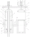
FIG. 2 is a sectional view of a structure of the universal tooling;
FIG. 3 is an enlarged view of FIG. 2A;
FIG. 4 is an enlarged view of FIG. 2B;
FIG. 5 is a view showing an installation structure of an anode according to the present invention;
FIG. 6 is a schematic view of the pod;
FIG. 7 is a view of the configuration of the baffle;
FIG. 8 is a perspective view of the tooling in cooperation with the electroplating apparatus (anode removed);
FIG. 9 is an enlarged view of FIG. 8C;
FIG. 10 is a view showing the construction of a pretreatment apparatus;
FIG. 11 is a side view of the pretreatment apparatus;
FIG. 12 is a plan view of the pretreatment apparatus;
FIG. 13 is a view showing the pretreatment apparatus and the tool;
FIG. 14 is a structural view of an ash removing apparatus;
FIG. 15 is a side view of the ash removal device;
FIG. 16 is an expanded view of a V-shaped groove of the ash removal device (3a refers to a transducing head arrangement).
Detailed Description
As shown in the figure: the general-purpose type slot external electroplating system for the cylinder body of the embodiment,
the device comprises a pre-plating treatment device, an electroplating device and a universal tool; according to the pre-plating treatment device and the electroplating device disclosed by the invention, as shown in fig. 1, the pre-plating treatment device comprises an etching station, a passivation station, an activation station and a zinc conversion station (the middle part is also provided with water washing, and the details are not repeated herein); certainly, the method also comprises the procedures of automatic oil removal, feeding and discharging and the like, which are not described again; the electroplating device generally comprises a pre-plating process and a plating process, and the protection scope of the invention is not limited to nickel plating, but includes all cyclic electroplating processes realized by the system of the invention, and the details are not repeated;
the universal tool comprises a mounting frame assembly and an installation auxiliary assembly, wherein the mounting frame assembly comprises a fixing frame and a pressing assembly 1;
the fixed frame comprises a bottom plate 2 and a frame fixed on the bottom plate 2;
the installation auxiliary assembly is used for installing a workpiece, compensating the height and the diameter of the workpiece, installing the workpiece on the bottom plate and pressing the workpiece through the pressing assembly 1, and is also used for introducing pretreatment liquid into the cylinder body to form a pretreatment environment in a pretreatment plating process, introducing electroplating liquid into the cylinder body in an electroplating process and enabling an anode to form an electroplating environment with the workpiece through the anode;
the bottom plate is arranged on the flow guide installation component 11, and the flow guide installation component is used for installing an anode and guiding electroplating solution to a workpiece to form an electroplating environment;
when the tool is used, the mounting frame assembly and the mounting auxiliary assembly on which the workpiece is mounted form a whole, the whole is transferred to each station of electroplating, when the mounting frame reaches the electroplating station, the mounting frame is directly placed on the flow guide mounting assembly (mounted on the corresponding electroplating station), the overall height is adjusted by the mounting auxiliary assembly matched with the workpiece to be matched with the anode, and different workpieces 9 do not need to be replaced, so that a production line does not need to be stopped, different workpieces are replaced and directly mounted on the tool and placed on the electroplating device, the matched mounting auxiliary assembly can also form transition between the workpiece and the electroplating device, the difference between different inner diameters of different workpieces and a bottom plate channel is compensated, and the universality on the height and the diameter is formed;
the installation auxiliary assembly can adopt a cylindrical structure, is matched with the workpiece 9 in height, so that the total height is matched with the height of the anode, and the inner diameter of the cylindrical structure is variable, so that the installation auxiliary assembly is suitable for transition between a bottom plate channel and the inner diameter of the workpiece, and is not repeated herein; of course, the structure of the installation auxiliary assembly is not necessarily cylindrical, and can be any shape for achieving the above purpose, and the description is omitted;
the pressing component 1 is arranged on the fixing frame and is used for pressing the workpiece and the installation auxiliary component, so that the stability of the workpiece during transportation and electroplating is ensured, and the electric quality and the electroplating process are ensured to be smoothly carried out;
the tool adopts an integral module, the whole body is sent to the flow guide installation assembly, a unique and simple electroplating environment is formed, the installation and the positioning are convenient, the automatic electroplating outside the tank is favorably realized, and the working efficiency is greatly improved; the overall height is adjusted to be matched with the anode through the installation auxiliary assembly matched with the workpiece, the anode does not need to be replaced for different workpieces, so that the production line does not need to be stopped, different workpieces are replaced and directly installed on the tool and placed in the electroplating device, and the matched installation auxiliary assembly can also compensate the difference between different inner diameters of the different workpieces and the bottom plate channel, so that the universality on the height and the diameter is formed; therefore, the invention has universality for electroplating outside the cylinder body and is suitable for workpieces with various sizes, realizes seamless switching of products, avoids capacity loss caused by wire stop, quickly meets delivery requirements, reduces switching time of mature products to the minimum, and reduces capacity loss to the minimum.
As shown, the electroplating apparatus includes an anode 15, a flow guide 16, and an electroplating environment forming assembly;
the anode 15 is arranged in an electroplating environment forming assembly and forms an electroplating environment around the anode 15, and the flow guide piece 16 is used for introducing electroplating solution into the electroplating environment, flowing into the center of the anode 16 from the top end of the anode and refluxing;
the flow guide piece 16 is provided with a plurality of flow distribution holes 1602 for passing the electroplating solution, and the flow distribution holes 1602 are uniformly distributed on a circulation interface of the electroplating solution;
the electroplating environment forming assembly refers to an environment capable of forming electroplating outside the cylinder body tank, namely a common dynamic electroplating environment, and is not described herein again;
introduce the electroplating environment through distributing hole 1602 with the plating solution, can guarantee the even stable flow of plating solution for effective ion distribution in the electroplating environment is even, thereby reaches the electroplating effect of expectation.
In this embodiment, the electroplating environment forming assembly includes a flow guide mounting assembly 11, the flow guide mounting assembly 11 includes a flow guide mounting cover 1102 and a supporting plate 1101 mounted on the flow guide mounting cover, the supporting plate 1101 is provided with a supporting plate channel for mounting the flow guide mounting cover 1102, and the supporting plate is isolated from the electroplating environment by the flow guide mounting cover 1102;
the flow guide mounting cover 1102 is provided with a flow guide central channel, the anode is mounted at the bottom of the flow guide mounting cover and upwards penetrates through the flow guide central channel, the flow guide piece is provided with a flow guide part, the flow guide part is sleeved outside the anode, the flow distribution holes are formed in the flow guide part and distributed around the anode, and the outer side edge of the flow guide part is attached to the side wall of the flow guide mounting cover; the lower part of the flow guide cover positioned at the drainage part is provided with an electroplating liquid inflow port; as shown in the figure, the bottom of the diversion installation cover is provided with an anode installation hole, the anode is of an integral structure, the lower part of the diversion installation cover is of a stepped shaft structure, the small shaft diameter section is provided with external threads and downwards penetrates through the anode installation hole 1105, the shaft shoulder of the stepped shaft supports against the edge of the anode installation hole, and the locking nut 17 is matched with the external threads of the anode 15 to lock and realize anode installation.
As shown in the figure, the anode of the invention has an integral structure, is formed in one step, has less manufacturing procedures, low difficulty and low total cost; the integral mounting structure avoids the occurrence of loosening and desoldering faults, the force can be applied safely during replacement, the anode is not damaged, and the time-consuming and labor-consuming repair and maintenance work is saved; the locking nuts are adopted to realize the tight contact and self-locking of the threads, and the tightening force is larger than that of other existing mounting structures; the conductive effect is easier to ensure, (in order to ensure that the screw thread has enough hardness and strength), a small amount of antimony is added into the anode alloy (generally lead-tin alloy).
In the structure, the electroplating solution flows out from the periphery of the anode 15 through the distribution holes, so that the whole structure is stable and uniform, and the structure is simple and compact; the plating solution inlet is generally provided with a plating solution connector which is communicated with a plating solution pump and supplies the plating solution, and the plating solution flows upwards into the plating environment through the distributing hole during the input, has a stirring effect, and is dispersed and uniform.
In this embodiment, the flow guiding member is a T-shaped sleeve sleeved on the anode, a flange 1601 of the T-shaped sleeve is a flow guiding portion, and the flow distributing holes 1602 are uniformly distributed on the flange 1601 of the T-shaped sleeve; as shown in the figure, the T-shaped sleeve, namely the upper end of the cylindrical structure protrudes outwards to form an annular flange, the structure is simple and compact, and the T-shaped sleeve is stably and simply matched with the anode 15; the upper end of the inner circle of the drainage part is a conical surface with a large upper part and a small lower part, and the outlet of the flow distribution hole is positioned on the conical surface; the structure that the outlet of the distributing hole is located on the conical surface enables electroplating solution to form downward rotational flow after flowing out of the distributing hole, and the space between the conical surface and the outer circle of the anode has a liquid storage function, so that the electroplating solution flowing out of the distributing hole is prevented from forming local unstable impact on an electroplating environment.
In this embodiment, the installation auxiliary assembly includes a variable diameter compensation part 3, the variable diameter compensation part 3 is a cylinder with an axial through hole and can be installed on the bottom plate in a positioning manner and insulate the bottom plate from the electroplating environment, and the axial through hole is communicated with the inner hole of the workpiece for leading in electroplating solution through the anode; the lower ends of the different reducing compensation parts 3 have the same external dimension, the upper ends have the internal diameter dimension which is matched with the internal diameter of the corresponding workpiece, the total height of the reducing compensation parts after the workpieces are installed can be matched with an anode to finish electroplating, and when the reducing compensation parts are used, the workpieces are axially pressed on the reducing compensation parts by the pressing assembly;
workpieces (air cylinders) with different heights and diameters are provided with variable-diameter compensation pieces 3 with different heights, so that the total height of the workpieces arranged in the invention is not changed, and the workpieces can be matched with the height of an anode; as shown in the figure, the fixed diameter size of the lower ends of different reducing compensation pieces (different reducing compensation pieces matched with different workpieces) can be matched and installed with a standard tool, the upper ends of the different reducing compensation pieces correspond to the inner diameters of the corresponding workpieces (concentric with the same diameter), the lower ends of the different reducing compensation pieces are used for penetrating through a channel matched with a bottom plate (so that the bottom plate is isolated from an electroplating environment), the upper parts of the different reducing compensation pieces are matched with the workpieces (different workpiece matching sizes have differences), and the total height of the reducing compensation pieces after the workpieces are installed enables the total height to be matched with the height of an anode to complete electroplating when in use, so that the device has universality; the reducing compensation part 3 is made of glass fiber reinforced plastic (certainly, other non-conductive materials with certain strength can be adopted, and the description is omitted), so that the reducing compensation part has an insulation effect and improves the electroplating efficiency.
The diversion installation cover 1102 is used for installing an anode and introducing electroplating solution into an electroplating environment (the electroplating environment refers to an environment forming electroplating after electrification, and generally refers to an environment between a workpiece and the anode), the bottom plate 2 is attached to the upper surface of the supporting plate 1101 and is installed on the supporting plate, and a channel for introducing the electroplating solution of the diversion installation cover is communicated with the reducing compensation part; as shown in the figure, a diversion installation cover installation position for installing a diversion installation cover is arranged on the supporting plate 1101 (as shown in the figure, an annular flange formed by bending and bending the upper end of the diversion installation cover outwards is arranged at the edge of the supporting plate channel, a step sinking groove is formed on the edge to enable the annular flange to be leveled after the annular flange is arranged at the edge), the diversion installation cover is arranged at the diversion installation cover installation position, the upper end of the diversion installation cover is hermetically abutted with the lower end of the reducing compensation part (namely the diversion installation cover penetrates through the supporting plate channel to enable the supporting plate not to contact with an electroplating environment), the bottom plate is attached to the upper surface of the supporting plate, and the diversion installation cover is used for installing an anode and leading in electroplating solution; by adopting a relatively modularized mounting structure and a mode of attaching and mounting the supporting plate 1101 and the bottom plate 2, the whole structure is simple, the mounting and positioning are convenient, the automatic electroplating outside the tank is favorably realized, and the working efficiency is greatly improved; the flow guide mounting cover is made of glass fiber reinforced plastic (other non-conductive materials with certain strength can be adopted, and the description is omitted), has an insulation effect, ensures the electroplating quality, and is provided with functional holes, such as an anode mounting hole for mounting an anode, a drainage member mounting hole for introducing electroplating solution, and the like, which are not described again; as shown in the figure, a sealing ring (gasket) 104 is arranged between the upper end of the flow guide mounting cover and the lower end of the reducing compensation part 3 to form radial sealing, prevent the electroplating solution from leaking along the radial direction and insulate with the outside.
In this embodiment, the installation auxiliary assembly further comprises a shielding member, the shielding member comprises an upper shielding ring 7 and a lower shielding ring 10 which are made of a non-metal conductive material, the lower shielding ring 10 is coaxially embedded into the axial through hole of the reducing compensation member 3 and axially abuts against the lower end of the workpiece 9 in the same diameter, and the upper shielding ring 7 abuts against the upper end of the workpiece 9 in the same diameter and is axially compressed by the compression assembly 1; the reducing compensation part is made of non-conductive materials, so that a stable electroplating working condition is formed on a conductive part, and the waste of materials and the interference to the electroplating working condition are avoided; the same-diameter mutual abutting means that the inner diameter of the upper shielding ring 7 and the inner diameter of the lower shielding ring 10 are the same as and coaxial with the inner diameter of the workpiece 9, edge burrs generated in the electroplating process are led to the upper edge of the upper shielding ring and the lower edge of the lower shielding ring in the electroplating process so as to ensure the electroplating quality, and the upper shielding ring 7 and the lower shielding ring 10 are made of conductive materials, so that the description is omitted; of course, radial seals are required to be formed between the upper shielding ring 7 and the lower shielding ring 10 and the workpiece 9 (cylinder) to prevent the electroplating solution from leaking; the lower end face (contacted and abutted with the upper end face of the cylinder body) of the upper shielding ring 7 and the upper end face (contacted and abutted with the lower end face of the cylinder body) of the lower shielding ring 10 are respectively provided with a sealing ring 12 and a sealing ring 13 (an annular sealing ring groove can be arranged on the corresponding end face and is used for placing the sealing ring), the sealing ring is generally made of acid and alkali resistant fluororubber, and the purposes of sealing and contact abutment can be realized through external force compression deformation; the lower end of the inner circle of the upper shielding ring forms an annular chamfer, the upper end of the inner circle of the lower shielding ring forms an annular chamfer, and the chamfer structure can guide burrs to grow towards a sudden change position, so that the interference on electroplating of the cylinder body is avoided, and meanwhile, the structure is favorable for ensuring that the interference on the flow of electroplating solution is not generated; the upper shielding ring and the lower shielding ring are made of non-metal conductive materials (such as conductive rubber or plastics), when in actual use, the inner plating layer can be separated from the upper shielding ring and the lower shielding ring by using a small external force (because the binding force between the non-metal conductive materials and a metal plating layer is generally small), for example, the plating layer can be directly peeled off by using a sharp tool, or the upper shielding ring and the lower shielding ring can be deformed by using a small external force (such as hand holding) to peel off the plating layer, the non-metal conductive materials with the set elastic modulus can be deformed by using the non-metal conductive materials with the set elastic modulus, but can bear the pressing force of a workpiece during electroplating to ensure the smooth operation of the electroplating process, so that the plating layer and burrs of the inner circle of the shielding ring can be separated from the inner circle of the shielding ring, the shielding ring can be used for the second time, and meanwhile, the plating layer and the burrs of the inner circle can be recovered, the consumption and the electroplating cost are reduced; and metallic shield ring (generally for aluminium) cladding material and burr and shielding ring combine closely, can't drop, adopt chemistry to remove the mode of cladding material and handle, need provide and remove the plating place to the shielding ring removes to plate many times the back can influence the later stage and use and scrap, and the cladding material also can't be retrieved and along with the waste liquid discharges, causes very big waste.
In the embodiment, the upper shielding ring and the lower shielding ring are both made of POM (polyoxymethylene) material and carbon powder, the addition proportion is less than or equal to 1% by mass, and about 0.4% is preferred, so that the conductive coating has good physical properties and chemical properties, good conductivity, easy shedding of the coating, long-term use without replacement and electroplating cost saving.
Because the plating layer can be stripped by a simple physical method, a deplating process is not needed, the shielding ring is hardly lost, the service life is long, the shielding ring can be continuously used for half a year to one year, and the low consumption cost for manufacturing the shielding ring every month can be reduced by over 75 percent; nitric acid is not used for stripping the shielding ring, the requirement of environmental protection is met, the stripping cost of the used nitric acid can be reduced by over 60 percent, the stripping time does not need to be waited, the nitric acid can be quickly put into the next round for use, and the nitric acid can be used for daily standby by 20 percent; no wastewater treatment pressure and corresponding cost are required; the stripped nickel layer can be recycled, thereby saving the field and reducing the cost.
In this embodiment, the installation auxiliary assembly further includes a positioning sleeve 8, the positioning sleeve 8 is provided with a positioning pin 801 which is matched with an installation threaded hole on the workpiece 9, and is positioned by the positioning pin 801 so that the positioning sleeve is concentric with the workpiece, and the upper shielding ring 7 is concentrically arranged in the positioning sleeve 8 and is concentrically matched with the workpiece 9 in the same diameter by the positioning sleeve 8;
the mounting threaded hole on the workpiece 9 refers to a threaded hole on the end face of the workpiece, the positioning sleeve aims to ensure that the positioning sleeve 8 is concentric with the workpiece by utilizing the matching between the positioning pin and the mounting threaded hole (the positioning pin is inserted into the threaded hole to form positioning), and the upper shielding ring 7 is mounted on the inner circle of the positioning sleeve so as to form coaxial matching with the workpiece in the same diameter; the locating pin generally is two at least, and this embodiment is two that the symmetry set up promptly, guarantees positioning accuracy.
The specific installation process is as follows: the reducing compensation part 3 is positioned and placed on a bottom plate 2 (a usable sealing ring, the sealing ring can be made of EVA foam cotton), the lower shielding ring 10 is placed on the reducing compensation part 3, a seal (the sealing mode is not limited) can be arranged between the lower end and the reducing compensation part 3, the sealing ring is placed on the upper end face of the lower shielding ring 10, a workpiece is placed on the lower shielding ring, the upper shielding ring is placed after the positioning is carried out through a positioning sleeve, a movable module can be formed by pressing through a pressing device, the module is directly conveyed to a flow guide mounting assembly and placed on a supporting plate after the positioning is carried out through positioning protrusions, and other external forces are utilized to compress the module.
In this embodiment, the lower end of the outer circle of the variable diameter compensation part 3 forms a stepped shaft structure, the small-diameter shaft section penetrates through the bottom plate channel 201, and a radial seal is formed between the end surface and the upper end surface of the flow guide installation cover;
the supporting plate 1101 is provided with at least two positioning protrusions 1103 which protrude upwards, so that high-precision positioning is achieved, the bottom plate 2 is provided with the positioning holes 202 which are used for being matched with the positioning protrusions 1103, and coaxiality of anode installation of the flow guide installation cover, a bottom plate channel, the reducing compensation part and a workpiece can be guaranteed after positioning installation, so that a good electroplating effect is guaranteed.
In the embodiment, the frame is provided with a fixed upper longitudinal beam 6, the pressing component 1 is arranged on the upper longitudinal beam 6, and a pressing part 5 which can be driven to reciprocate up and down is arranged for pressing or releasing a workpiece 9; the structure can adopt any existing mechanical structure, including manual or electric, and can be realized by adopting the existing mechanical structure, which is not described again; as shown in the figure, the frame includes four upright posts 4 detachably fixed on the bottom plate 2 (by bolts), two upright posts 4 are respectively disposed on two longitudinal sides (according to the arrangement direction of the plurality of workpieces), an upper cross beam 12 is fixedly connected between the upper portions of the two upright posts 4 (by bolts), and the upper longitudinal beam 6 is fixedly connected between the two upper cross beams 12 to form a stable structure of fixed connection, which is not described herein again.
In this embodiment, the pressing assembly 1 includes a pressing rod 101 capable of being driven to reciprocate up and down along the upper longitudinal beam 6 and a lever assembly for driving the pressing rod 101 to reciprocate, and the pressing portion 5 is located at the lower end of the pressing rod 101; the lever assembly comprises a driving lever (comprising a power arm 1021 and a resistance arm 1022) and a rocker arm, wherein the resistance end (namely the end part of the resistance arm) of the lever is rotatably hinged at the upper end of the pressing rod 101, the lower end of the rocker arm can rotate in a single degree of freedom relative to the upper longitudinal beam, and the upper end of the rocker arm is coaxially hinged with the fulcrum of the driving lever in a single degree of freedom rotation; a limiting block 104 is arranged on the rocker arm, and the limiting block 104 limits the lever to continue rotating towards the pressing direction when the lever is driven to drive the pressing rod 101 to press the workpiece;
the reciprocating motion of the pressing rod 101 is generally single degree of freedom, that is, only reciprocating motion is performed, the pressing part 5 can be integrally formed with the pressing rod 101 or can be detachably arranged in a split manner, in the embodiment, the pressing part with a plate-shaped structure is adopted, and the pressing part is generally movably connected with the end part of the pressing rod with a certain degree of freedom, such as a movable head like a ball hinge, so that the pressing end face can be adapted to, and the coaxiality of workpieces can be ensured;
the upper end of the rocker arm is hinged with the fulcrum of the driving lever through the fulcrum hinged shaft 14, the driving lever rotates around the fulcrum under the action of external force to enable the resistance arm 1022 to approach to be vertical from the transverse direction, so that the pressing rod 101 is driven to press a workpiece downwards, the rocker arm swings forwards around the hinged point at the lower end of the rocker arm under the transverse (no displacement) constraint of the pressing rod 101, when the resistance arm 1022 presses the workpiece, the fulcrum axis is at least intersected with the fulcrum hinged axis (the axis of the hinged shaft 14) or exceeds the hinged axis backwards, so that self-locking is formed, the lever is prevented from rotating under the reaction force, meanwhile, the limiting block limits the lever to rotate continuously in the pressing direction, so that the pressing rod is prevented from rotating continuously to drive the pressing rod to move upwards, and pressing self-locking is formed (namely, the mechanical structure formed by the pressing rod and the driving lever is similar to a connecting rod crank structure, but limited by the limiting block, so that the circular motion similar to the connecting rod crank is avoided, thereby forming a self-lock).
In this embodiment, the pressing assembly 1 further includes a base, the base is fixed to the upper longitudinal beam 6, the pressing rod 101 is disposed on the base in a manner of single-degree-of-freedom up-and-down reciprocating motion, the two rocker arms are respectively arranged on two sides of the base (the rocker arm 1031 and the rocker arm 1032), the lower ends of the two rocker arms are coaxially hinged to the base, and the upper ends of the two rocker arms are respectively coaxially hinged to two sides of a fulcrum of the driving lever (i.e., the two rocker arms rotate coaxially with the driving lever at the fulcrum); when the pressing rod 101 presses a workpiece through the pressing part, the axis of the pressing rod is intersected with or exceeds the axis of the fulcrum backwards, and at the moment, the limiting block supports against the resistance arm of the driving lever from the back side;
as shown in the figure, the base is fixed on the surface of the upper longitudinal beam 6 through a detachable structure, and a through hole for the compression rod to pass through is formed in the upper longitudinal beam 6; the base comprises a base plate 105 and a guide sleeve 107, the guide sleeve is provided with a guide slideway, the guide slideway is vertically arranged right opposite to the through hole on the upper longitudinal beam, and the pressing rod penetrates through the guide slideway and is matched with the guide slideway in a way of reciprocating up and down; the base plate 105 is detachably connected with the upper longitudinal beam 6 through a connecting hole (a bolt passes through, and a waist-shaped hole is generally adopted), so that the base plate has strong adaptability; the guide sleeve 107 is fixed on the base plate 105 through threaded connection, and the structure is simple; as shown in the figure, the lower end of the guide sleeve 107 is provided with external threads, and is screwed on the internal threads on the base plate 105 in a manner that the axis (the direction of the guide slideway) is vertical to the base plate 105 to form connection, and in order to avoid falling off, the connection is also locked by a locking nut 106; the pressing rod passes through the guide sleeve 107 along the vertical direction and is matched with the guide sleeve in a reciprocating motion (generally, the pressing rod has a single degree of freedom); the lower ends of the rocker arms 1031 and 1032 are symmetrically hinged to two sides of the guide sleeve 107 respectively, the structure is simple and practical, the whole locking assembly forms a module, and the hinged part is installed on the base plate after being completely processed;
the backward direction in the present invention refers to the direction (the direction indicated by the arrow in fig. 4) in which the power arm 1022 swings when the driving lever presses the workpiece, and the back side is the side corresponding to the backward direction, which is not described herein again.
Due to the action of the stopper 14, the resistance wall 1022 of the lever is prevented from further rotating, the rocker arm 1031 and the rocker arm 1031 cannot further rotate under the action of the stopper, that is, an interlock is formed, and the axis of the compression rod intersects with or goes back beyond the axis of the fulcrum (generally, the axes intersect), that is, a stable retraction mechanism is formed, and the release is avoided.
In this embodiment, the base is detachably and fixedly connected to the upper longitudinal beam 6, the driving lever is a right-angle structure taking a fulcrum as a boundary, the resistance arm 1022 forms a fork-shaped groove, the compression bar 101 is located in the fork-shaped groove and is hinged to the end of the resistance arm, the fork-shaped structure is beneficial to stable connection and does not apply a biasing force, so that the structure is stable and the service life is long; as shown in the figure, the driving lever is a right-angle structure (i.e. the power arm 1021 and the resistance arm 1022 are right-angled) using the fulcrum as a boundary, i.e. at the fulcrum, the power arm is bent forwards, so that the operation is convenient and the interference with the rocker arm (the limiting block) is avoided.
In this embodiment, the workpiece 9 is in tight contact with the upper shield ring 7 and the lower shield ring 10 to form a radial seal, which means that a seal ring is disposed on an end surface to prevent liquid from leaking in a radial direction.
In this embodiment, the reducing compensation part 3 is installed on the bottom plate 2 in a positioning manner and is coaxial with the bottom plate channel 201, a step for placing the lower shielding ring 10 is arranged on the inner circle, and the inner diameter of the step is larger than that of the lower shielding ring 10, so that the stable flow of the electroplating solution is ensured; the upper shielding ring 7 is coaxially arranged on the inner circle of the positioning sleeve 8, and the pressing component 1 presses the workpiece 9 through the upper shielding ring 7; the reducing compensation part 3 can be arranged on the bottom plate 2 in a positioning manner, and can adopt various mechanical structures, for example, an annular sinking groove is formed on a bottom plate channel 201 (the shape is the same as the radial overall dimension of the reducing compensation part, the reducing compensation part is arranged in the annular sinking groove to form transverse positioning, namely, a coaxial effect is achieved, or the reducing compensation part shown in the figure can be matched with the bottom plate channel through a shaft shoulder (stepped shaft) structure, namely, a small-diameter part penetrates through the bottom plate channel, and a shaft shoulder of a large-diameter part is pressed on the edge of the bottom plate channel to form positioning;
the part directly contacted with the workpiece (cylinder body) is generally sealed by an acid and alkali resistant fluororubber sealing ring, such as the sealing between the upper and lower shielding rings and the workpiece, so that the sealing is ensured, and meanwhile, the close contact between the shielding rings and the workpiece cylinder body can be ensured to successfully transfer burrs; the sealing which is not in direct contact with the workpiece adopts EVA foam (such as between a lower shielding ring and a reducing compensation part) so as to reduce the clamping action of an operator for placing/taking out the rubber ring and improve the clamping efficiency; as shown in the figure, the bottom plate is provided with a positioning hole for positioning the bottom plate on the electroplating device, after a workpiece is installed on the device, the tool is moved to the electroplating device and is matched with the positioning protrusion 1103 on the supporting plate 1101 through the positioning hole space 202, so that the installation position is matched with an electroplating solution flow channel of the device, and the normal operation of electroplating is ensured.
In this embodiment, the pre-plating treatment device comprises a pre-plating flowing liquid treatment device, and the pre-plating flowing liquid treatment device comprises a treatment unit, a liquid supply assembly and a liquid return assembly;
the processing unit comprises a base body, wherein the base body is provided with an upper part for placing a universal tool;
the upper part of the base body is provided with a liquid inlet and a liquid return port, and the inner cavity of the workpiece of the universal fixture is communicated with the liquid inlet and the liquid return port after the universal fixture is arranged on the upper part;
the liquid return assembly comprises a communicating pipe communicated with the liquid return port, and the outlet height of the communicating pipe is higher than the height of the part of the workpiece to be processed;
in the step of treating the flowing liquid before plating, the bottom plate of the universal tool is matched with the upper part, so that the axial through hole of the reducing compensation piece is communicated with the liquid inlet and the liquid return port for introducing the pre-plating treating liquid;
the pre-plating flowing liquid treatment device ensures that the pre-plating treating liquid in the workpiece keeps a set height through the communicating vessel principle, the liquid inlet and the liquid outlet are communicated with the inner cavity of the workpiece, and the liquid inlet and the liquid outlet can be set in size ranges so as to adapt to cylinders with double cylinders or single cylinders and cylinders with different cylinder hole pitches, and the device has universality.
The liquid supply assembly generally includes a liquid supply pump and a liquid supply pipeline, and a liquid supply tank is required to be arranged, which is not described in detail herein.
In this embodiment, the liquid inlet 25011 and the liquid outlet 25012 are both strip-shaped or are formed by arranging a plurality of holes in parallel into a strip shape, the present embodiment adopts a strip shape, which is convenient for processing and forming, the lower part of the tool and the upper part of the substrate form a seal, the sealing part is positioned around the liquid inlet and the liquid return port, when in use, the lower part of the tool and the upper part of the substrate are in sealing joint (the sealing mode is different according to the structure of the upper part and the lower part, and the existing mechanical static sealing structure can be adopted or selected), the sealing part is positioned around the liquid inlet 25011 and the liquid return port 25012, so as to form a closed flowing state;
in this embodiment, the upper portion of the substrate 25 is an upper plane 2501, the lower portion of the tool is a lower plane, when the tool is used, the lower plane of the tool is in sealing fit with the upper plane 2501 of the substrate, and the sealing portion is located around the liquid inlet 25011 and the liquid return port 25012; the joint part is sealed through the joint of the upper plane and the lower plane, the inner hole of the workpiece is communicated with the liquid inlet and the liquid outlet to form circulation, and when the treatment liquid in the inner hole of the workpiece reaches the height of the communicating pipe, the pre-plating treatment is carried out and finished; as shown in the figure, the sealing position refers to a sealing groove (as shown in the figure, surrounding the liquid inlet and the liquid outlet, and being set according to the use condition, on the premise of not leaking the processing liquid, a general static sealing manner can be realized, which is not described herein), and a sealing ring (gasket) 23 is arranged in the sealing groove 2505.
In this embodiment, a liquid inlet channel 2502 and a liquid return channel 2503 are arranged inside the substrate 25, the liquid inlet channel 2502 is communicated between the liquid supply system and the liquid inlet 25011, and the liquid return channel is communicated between the liquid return port 25012 and the liquid return component; the liquid inlet channel 2502 and the liquid return channel 2503 are directly machined in the substrate 25, the manufacturing is simple and convenient, modularization is formed, the cost is low, and sealing is not needed; the machining mode can be the existing mechanical machining mode (casting or post-drilling), and the details are not repeated.
In this embodiment, the liquid return assembly further includes a liquid return pipe and a liquid return tank 31, the communication pipe 30 is located in the liquid return tank 31, and the liquid return pipe is communicated between the liquid return channel 2503 and the communication pipe 30; the liquid supply assembly comprises a liquid supply pipe and a liquid supply pump, the liquid supply pipe is communicated between the liquid inlet channel and the liquid supply pump, the structure is simple and practical, the arrangement is convenient, and the liquid supply assembly has strong adaptability.
In this embodiment, the processing units are arranged in parallel, and the liquid return pipes include liquid return branch pipes 27 correspondingly communicated with the liquid return channels 2503 of the processing units, and liquid return header pipes 28 converging the liquid return branch pipes 27 and communicated with the communicating pipes; the liquid supply pipe comprises liquid supply branch pipes 19 correspondingly communicated with the liquid supply channels of the processing units and a liquid supply main pipe 20 which supplies liquid to the liquid supply branch pipes 19 and is communicated with the liquid supply pump; the structure greatly improves the working efficiency of the pretreatment process; as shown in the figure, four processing units are arranged in parallel along the longitudinal direction, and a plurality of processing units may share one substrate, or each processing unit may be an independent substrate, which is not described herein again; of course, the processing unit needs to be installed on the base or pedestal of the dynamic electroplating production line, and will not be described in detail herein.
In this embodiment, the liquid supply branch pipe 19 is provided with an adjusting valve 24 (generally, a ball valve or a plug valve, which can be used for adjusting the flow rate), the opening degree of the adjusting valve at the far end from the liquid supply pump is gradually increased, that is, the opening degree is larger the farther away from the liquid supply pump, the adjusting valve can be timely adjusted according to the liquid level height in the workpiece, and finally the effect that the liquid levels of all the processing units are basically flush is achieved; namely, the plurality of processing units are respectively provided with the liquid supply branch pipes 19 and the regulating valves 24, the pipeline resistance of the liquid supply branch pipes far away from the liquid supply pump is relatively large, and under the action of the communicating vessel principle, the far end does not reach the set height and the near end reflows, so that the plating pretreatment of the far end cannot be normally carried out; therefore, the opening of the regulating valve is set to adjust the pipeline resistance to be close or the same, thereby smoothly completing the pre-plating treatment of a plurality of treatment units.
In the embodiment, the liquid level sensor assembly is used for detecting the overflow height of the communicating pipe, detecting the liquid level height and transmitting the liquid level height to the control center, monitoring the liquid level height and ensuring the smooth proceeding of the pre-plating treatment, and all the existing liquid level sensors can be adopted to achieve the aim of the invention.
In this embodiment, the liquid return assembly further includes a liquid return buffer slot 29 which is closed and communicated with the liquid return pipe, the liquid return buffer slot 29 is located in the liquid return slot, and the communicating pipe 30 is vertically inserted into the liquid return buffer slot 29, as shown in the figure, the communicating pipe 30 is connected to the upper cover of the liquid return buffer slot 29 through a thread, so as to be inserted into the buffer slot, and as the buffer slot is of a closed structure, the treatment liquid entering the buffer slot overflows through the communicating pipe, thereby realizing the final purpose of the communicating vessel; the liquid level sensing subassembly includes detecting tube 21 and float sensor 22, the vertical liquid buffer tank that returns that inserts of detecting tube, the adjustable height of float sensor sets up in the detecting tube, and equally, the detecting tube passes through threaded connection in the upper cover that returns the liquid buffer tank and inserts back the liquid buffer tank, and float sensor threaded connection sets up in the interior circle of detecting tube, and the detecting tube height should be higher than the overflow height of communicating pipe, no longer gives unnecessary details here.
In this embodiment, a strip-shaped groove is formed on the upper plane 2501 of the substrate 25 and is communicated with the liquid inlet channel 25011 and the liquid return channel 25012, the strip-shaped groove is provided with a liquid separation plate 26, two sides of the liquid separation plate 26 are sealed by the liquid separation plate 26 and form a liquid inlet 25011 and a liquid return port 25012 respectively; as shown in the figure, the two sides of the width of the strip-shaped groove are respectively communicated with the liquid supply channel 2502 and the liquid return channel 2503, the bottom of the groove is longitudinally provided with a strip-shaped embedding groove 1104 (fig. 2 and 3 are structures without a liquid separation plate), the lower part of the liquid separation plate 26 is embedded in the strip-shaped embedding groove to form installation and seal the two sides of the strip-shaped groove, and a liquid inlet and a liquid return port are formed between the two sides of the top of the liquid separation plate and the edge of the strip-shaped groove; of course, the liquid inlet and the liquid return port may be formed by directly processing a strip-shaped groove on the upper plane, which is not described herein again.
In this embodiment, the cross section of the upper part of the liquid separation plate 26 is a triangular structure with a large upper part and a small lower part, and a liquid inlet and a liquid return port are respectively formed between two ends of the bottom of the triangle and the edge of the strip-shaped groove; as shown in the figure, it can also be understood as a triangle structure (two sides are equal to an isosceles triangle structure or an isosceles trapezoid structure), in which the flow channels of the liquid inlet and the liquid outlet are respectively inclined to the radial direction, so that the flow is guided by the triangle side to flow along the radial direction, and directly acts on the inner wall of the cylinder body, thereby promoting the treatment effect, and guiding the treatment liquid to flow from the inner diameter side wall of the cylinder body to the liquid return port during the backflow, increasing the contact between the inner surface of the cylinder body and the treatment liquid, and improving the treatment efficiency.
In this embodiment, the height of the communication pipe 30 is adjustable, and the adjustable manner can adopt the existing mechanical structure, for example, the height of the communication pipe itself (a telescopic structure or a sectional threaded connection) can be adjusted to achieve the purpose of the invention; similarly, the detecting tube 21 is also of a height-adjustable structure, and is not described herein again;
when the pre-plating flowing liquid treatment device is used, the device is matched with a universal tool to achieve the purpose of use, and the description is omitted; the pre-plating flowing liquid treatment device is suitable for all processes of treating by the pre-plating treating liquid before plating of circular electroplating, including alkali etching, acid etching, activation, zinc conversion and a series of water washing processes, and is not described again.
In this embodiment, the pre-plating treatment device further includes a pre-plating ash removal device, the pre-plating ash removal device includes an ash removal groove 32 and an ultrasonic wave generation assembly, the ultrasonic wave generation assembly includes an energy conversion head (vibration head) and a driver, and the energy conversion head is located at the lower outer side of the ash removal groove; the energy conversion head is obliquely arranged, the bottom plate of the universal tool is placed at a set position of the ash removal groove during an ash removal process, and the ultrasonic generation direction of the energy conversion head is over against the range of the inner hole of the workpiece; the energy conversion head is positioned at the lower outer side of the ash removal groove, and is obliquely arranged so that the ultrasonic wave generating direction (which refers to the main generating direction of the energy conversion head and can be understood as the central line of the energy conversion head) of the energy conversion head is opposite to the range of the inner hole of the workpiece after the ash removal groove is used for placing the workpiece; the energy conversion head is used for generating ultrasonic waves, the ultrasonic waves penetrate through the side wall of the ash removal groove and act on the space in the ash removal groove, the ultrasonic waves act in a range, and the inner hole of a workpiece is positioned in the range and can adapt to different sizes of workpieces; when the tool is used, a workpiece is placed in the ash removal groove through the tool, the workpiece is located in the range of the ultrasonic waves of the energy conversion head, and the ash removal effect is achieved through the ultrasonic waves; the energy-changing heads are arranged according to the ash removing effect to achieve the final required effect; because the transducing head is arranged outside the tank body, the workpiece can not be interfered, and the device can be suitable for workpieces with various parameters.
In this embodiment, the two energy conversion heads 34 are divided into two groups and arranged at two sides below the ash removal groove 32, and the two groups of energy conversion heads are inclined in opposite directions so that the ultrasonic generation direction of the two groups of energy conversion heads is over against the range of the inner hole of the workpiece after the workpiece is placed in the ash removal groove 32; the superposition of the ultrasonic waves emitted by the two groups of energy-exchanging heads at the same frequency is enhanced, the ash removal strength in the range where the workpiece is located is facilitated, the ash removal effect in the height can be guaranteed, the ash removal requirement of the cylinder body before plating treatment in most specifications at present can be met by matching tool design, the structure arrangement is compact, and the number and the power of the energy-exchanging heads can be arranged according to requirements.
In this embodiment, the included angle between the ultrasonic generating directions of the two groups of transducing heads 34 is 45 to 75 degrees, the arrangement angle range can cover the range of the required dust removal, and the arrangement angle range has a better superposition effect, so that the overall intensity of the ultrasonic waves can be increased, and the efficiency is improved, preferably 60 degrees.
In this embodiment, a V-shaped sinking groove 33 with a V-shaped cross section is formed at the bottom of the ash removing groove 32, the two groups of transducing heads are respectively and correspondingly distributed on the two side groove walls of the V-shaped sinking groove 33, and an included angle between the two side groove walls (respectively, the groove wall 3301 and the groove wall 3302) of the V-shaped sinking groove 33 is adapted to an included angle between the ultrasonic generating directions of the two groups of transducing heads 34; as shown in the figure, the end part of the energy conversion head 34 is tightly attached to the outer sides of the two side groove walls of the V-shaped sunken groove 33, and the central line is perpendicular to the groove walls, so that the included angle between the two side groove walls (the groove wall 3301 and the groove wall 3302) of the V-shaped sunken groove 33 is related to the included angle between the ultrasonic wave generating directions of the two groups of energy conversion heads, and the sum is 180 degrees, of course, the central line can not be perpendicular to the groove walls, the included angle of the ultrasonic wave generating directions is ensured, the invention purpose can be achieved, the structure is simple and compact, and the installation is convenient.
In this embodiment, the ends of the two groups of transducing heads 34 are arranged close to the outer sides of the two side walls of the V-shaped sinking groove 33, and can be arranged as required to adjust the power of the ultrasonic wave, thereby achieving the final ash removal.
In this embodiment, the two groups of the energy conversion heads 34 each include a plurality of energy conversion heads, each group of the energy conversion heads 34 is arranged in at least two longitudinal rows, and the energy conversion heads 34 between adjacent rows are arranged in a staggered manner in the longitudinal direction, so that the ash removal gaps can be compensated, and therefore, complete ash removal is ensured; in this embodiment, each group of the transducing heads is two rows, and multiple rows can be adopted for achieving the efficient ash removing effect, which is not described herein again.
In this embodiment, the transducing heads 34 between adjacent rows of each set have a cross in the transverse direction, so that the ultrasonic waves further cover the position of the cylinder body, and no dead angle is formed for ash removal.
As shown in the figure, the distribution of the transducing heads on the mounting positions 34a of the transducing heads 34 on the unfolded V-shaped sunken groove
In this embodiment, the V-shaped sinking groove 33 is flat, the horizontal width of the flat bottom is not more than 40mm, a stable V-shaped structure is formed, the installation and the transportation are convenient, and meanwhile, the groove body, the energy conversion head and the tool are well supported.
In this embodiment, the depth of the V-shaped sinking groove 33 is not more than 90mm, and the transverse width can accommodate a tool (for installing a workpiece), so that the overall structure has a small volume, the tool is easy to place, and the ultrasonic waves on the two sides are easy to overlap, thereby improving the ash removal efficiency.
In the embodiment, the included angle between the two side groove walls of the V-shaped sinking groove is 120 degrees, the structure enables the ultrasonic wave emission directions of the energy conversion head to have most superposition, the integral ash removal efficiency is improved, and the power of the energy conversion head required by low pass is reduced; the energy conversion heads are arranged as far as possible downwards, namely, the energy conversion heads are arranged close to the bottom (flat bottom) of the V-shaped groove, and ultrasonic superposition in a longer range can be formed by combining the arrangement of included angles, so that the ash removal efficiency is further improved.
The ash removing device is matched with the universal tool, the universal tool is integrally placed in the ash removing groove 32, the bottom plate 2 is placed above the V-shaped groove, and the ash removal is realized through ultrasonic waves emitted by the energy conversion head 34; the tool can also adopt other structures, and the details are not repeated.
The plating outside the bath of the present invention refers to dynamic plating by circulating plating liquid outside the plating bath, and will not be described herein.
In this embodiment, an engine cylinder is taken as an example, and actually, the technical solution claimed in the present invention is not limited to the engine cylinder, but may be a compressor cylinder, a plunger pump cylinder, and other cylinders having similar structures, which are not described herein again.
Finally, the above embodiments are only for illustrating the technical solutions of the present invention and not for limiting, although the present invention has been described in detail with reference to the preferred embodiments, it should be understood by those skilled in the art that modifications or equivalent substitutions may be made to the technical solutions of the present invention without departing from the spirit and scope of the technical solutions of the present invention, and all of them should be covered in the claims of the present invention.
Claims (10)
1. The utility model provides a general type external cell plating system for cylinder body which characterized in that: the device comprises a pre-plating treatment device, an electroplating device and a universal tool;
the universal tool comprises a mounting frame assembly and an installation auxiliary assembly, wherein the mounting frame assembly comprises a fixing frame and a pressing assembly;
the fixing frame comprises a bottom plate and a frame fixed on the bottom plate;
the installation auxiliary assembly is used for installing a workpiece, compensating the height and the diameter of the workpiece, installing the workpiece on the bottom plate and compressing the workpiece through the compressing assembly, and is also used for introducing pretreatment liquid into the cylinder body to form a pretreatment environment in a pretreatment plating process, introducing electroplating liquid into the cylinder body in an electroplating process and forming an electroplating environment between the anode and the workpiece through the anode;
the installation auxiliary assembly comprises a variable-diameter compensating piece, the variable-diameter compensating piece is a cylinder with an axial through hole and can be positioned and installed on the bottom plate and insulate the bottom plate from an electroplating environment, and the axial through hole is communicated with an inner hole of the workpiece and is used for leading electroplating liquid through an anode; the lower ends of different reducing compensation parts have the same external dimension matched with the bottom plate, the upper ends of the different reducing compensation parts have the internal diameter dimension matched with the internal diameter of a corresponding workpiece, the total height of the reducing compensation parts after the workpieces are installed can be matched with an anode to finish electroplating, and when the reducing compensation parts are used, the workpieces are axially pressed on the reducing compensation parts by the pressing assembly;
the installation auxiliary assembly further comprises a shielding piece, the shielding piece comprises an upper shielding ring and a lower shielding ring, the upper shielding ring and the lower shielding ring are made of nonmetal conductive materials with set elastic modulus, the lower shielding ring is coaxially embedded into the axial through hole and axially abuts against the lower end of the workpiece in the same diameter, and the upper shielding ring abuts against the upper end of the workpiece in the same diameter and is axially compressed by the compressing assembly; the reducing compensation part is made of a non-conductive material;
the electroplating device comprises an anode, a flow guide piece and an electroplating environment forming assembly;
the electroplating environment forming assembly comprises a flow guide mounting assembly, the flow guide mounting assembly comprises a flow guide mounting cover and a supporting plate mounted on the flow guide mounting cover, a supporting plate channel for mounting the flow guide mounting cover is arranged on the supporting plate, and the supporting plate is isolated from the electroplating environment through the flow guide mounting cover;
the flow guide mounting cover is provided with a flow guide central channel, and the anode is mounted at the bottom of the flow guide mounting cover and upwards penetrates through the flow guide central channel; during the electroplating process, the bottom plate is attached to the supporting plate, so that the axial through hole of the reducing compensation part is communicated with the flow guide central channel of the flow guide mounting cover and is used for leading electroplating liquid into the inner hole of the workpiece through the anode.
2. A universal profiled slot electroplating system for a cylinder block as claimed in claim 1 wherein: the flow guide piece is provided with a flow guide part, the flow guide part is sleeved outside the anode, the flow guide part is provided with flow distribution holes which are distributed around the anode and used for allowing electroplating solution to pass through, and the outer side edge of the flow guide part is attached to the side wall of the flow guide mounting cover; the air guide sleeve is positioned at the lower part of the drainage part and is provided with an electroplating liquid inflow port.
3. A universal profiled slot electroplating system for a cylinder block as claimed in claim 2 wherein: the flow guide part is a T-shaped sleeve sleeved outside the anode, the flange of the T-shaped sleeve is a flow guide part, and the flow distribution holes are uniformly distributed on the flange of the T-shaped sleeve; the upper end of the inner circle of the drainage part is a conical surface with a large upper part and a small lower part, and the outlet of the flow distribution hole is positioned on the conical surface.
4. A universal profiled slot electroplating system for a cylinder block as claimed in claim 1 wherein: the pre-plating treatment device comprises a pre-plating flowing liquid treatment device, and the pre-plating flowing liquid treatment device comprises a treatment unit, a liquid supply assembly and a liquid return assembly;
the processing unit comprises a base body, wherein the base body is provided with an upper part for placing a universal tool;
the upper part of the base body is provided with a liquid inlet and a liquid return port, and after the tool is arranged on the upper part, a workpiece inner cavity on the universal tool is communicated with the liquid inlet and the liquid return port;
the liquid return assembly comprises a communicating pipe communicated with the liquid return port, and the outlet height of the communicating pipe is higher than the height of the part of the workpiece to be processed.
5. The universal ex-slot plating system for cylinder blocks according to claim 4, wherein: the liquid inlet and the liquid outlet are both in a strip shape or are formed by arranging a plurality of holes in parallel in a strip shape, the lower part of the bottom plate is a lower plane, the upper part of the base body is an upper plane, when the tool is used, the lower plane and the upper plane of the tool are in sealing fit, and the sealing part is positioned around the liquid inlet and the liquid return port.
6. The universal ex-slot plating system for cylinder blocks according to claim 5, wherein: a liquid inlet channel and a liquid return channel are arranged in the substrate, the liquid inlet channel is communicated between the liquid supply system and the liquid inlet, and the liquid return channel is communicated between the liquid return port and the liquid return assembly;
the liquid return assembly further comprises a liquid return pipe and a liquid return groove, the communicating pipe is positioned in the liquid return groove, and the liquid return pipe is communicated between the liquid return channel and the communicating pipe; the liquid supply assembly comprises a liquid supply pipe and a liquid supply pump, and the liquid supply pipe is communicated between the liquid inlet channel and the liquid supply pump;
the processing units are arranged in parallel, and the liquid return pipes comprise liquid return branch pipes correspondingly communicated with the liquid return channels of the processing units and liquid return main pipes converging the liquid return branch pipes and communicated with the communicating pipes; the liquid supply pipe comprises liquid supply branch pipes correspondingly communicated with the liquid supply channels of the processing units and a liquid supply main pipe which supplies liquid to the liquid supply branch pipes and is communicated with the liquid supply pump;
and the liquid supply branch pipe is provided with an adjusting valve, and the opening degree of the adjusting valve at the far end away from the liquid supply pump is gradually increased.
7. A universal profiled slot electroplating system for a cylinder block as claimed in claim 2 wherein: the liquid return assembly also comprises a liquid return buffer groove which is closed and communicated with the liquid return pipe, the liquid return buffer groove is positioned in the liquid return groove, and the communicating pipe is vertically inserted into the liquid return buffer groove; the height of the communicating pipe is adjustable.
8. A universal profiled slot electroplating system for a cylinder block as claimed in claim 1 wherein: the pre-plating treatment device further comprises a pre-plating ash removal device, the pre-plating ash removal device comprises an ash removal groove and an ultrasonic generation assembly, the ultrasonic generation assembly comprises a transducer head and a driver, and the transducer head is arranged at the lower outer side of the ash removal groove; the energy conversion head is obliquely arranged, and during the ash removal process, the bottom plate of the universal tool is placed at the set position of the ash removal groove, and the ultrasonic wave generation direction of the energy conversion head is just opposite to the range of the inner hole of the workpiece.
9. A universal profiled slot electroplating system for a cylinder block as claimed in claim 8 wherein: the two groups of the energy conversion heads are arranged on two sides below the ash removal groove in an opposite inclined mode, the bottom plate of the universal tool is placed at a set position of the ash removal groove during an ash removal process, and the ultrasonic wave generating direction of the energy conversion heads is over against the range of an inner hole of a workpiece.
10. A universal profiled slot electroplating system for a cylinder block as claimed in claim 9, wherein: the bottom of the ash removal groove forms a V-shaped sinking groove with a V-shaped cross section, the two groups of energy-converting heads are respectively and correspondingly distributed on the two side groove walls of the V-shaped sinking groove, the end parts of the two groups of energy-converting heads are tightly close to the outer sides of the two side groove walls of the V-shaped sinking groove, and the included angle between the two side groove walls of the V-shaped sinking groove is suitable for the included angle between the ultrasonic wave generating directions of the two groups of energy-converting heads; the two groups of the energy conversion heads comprise a plurality of energy conversion heads, each group of the energy conversion heads are arranged in at least two longitudinal rows, the energy conversion heads between the adjacent rows are arranged in a staggered mode in the longitudinal direction, and the energy conversion heads between the adjacent rows are crossed in the transverse direction.
Priority Applications (1)
| Application Number | Priority Date | Filing Date | Title |
|---|---|---|---|
| CN201911244524.4A CN111155155B (en) | 2019-12-06 | 2019-12-06 | Universal type groove external electroplating system for cylinder body |
Applications Claiming Priority (1)
| Application Number | Priority Date | Filing Date | Title |
|---|---|---|---|
| CN201911244524.4A CN111155155B (en) | 2019-12-06 | 2019-12-06 | Universal type groove external electroplating system for cylinder body |
Publications (2)
| Publication Number | Publication Date |
|---|---|
| CN111155155A CN111155155A (en) | 2020-05-15 |
| CN111155155B true CN111155155B (en) | 2021-09-14 |
Family
ID=70556532
Family Applications (1)
| Application Number | Title | Priority Date | Filing Date |
|---|---|---|---|
| CN201911244524.4A Active CN111155155B (en) | 2019-12-06 | 2019-12-06 | Universal type groove external electroplating system for cylinder body |
Country Status (1)
| Country | Link |
|---|---|
| CN (1) | CN111155155B (en) |
Family Cites Families (5)
| Publication number | Priority date | Publication date | Assignee | Title |
|---|---|---|---|---|
| JP3889315B2 (en) * | 2002-05-23 | 2007-03-07 | 日本精工株式会社 | Electrodeposition coating method for automotive hubs |
| JP4391893B2 (en) * | 2004-06-16 | 2009-12-24 | 本田技研工業株式会社 | Plating equipment |
| JP5167986B2 (en) * | 2008-06-30 | 2013-03-21 | スズキ株式会社 | Plating equipment |
| CN201793790U (en) * | 2010-08-24 | 2011-04-13 | 小康汽车产业(集团)有限公司 | Galvanic anode controllable shielding device |
| CN211734520U (en) * | 2019-12-06 | 2020-10-23 | 隆鑫通用动力股份有限公司 | Circulating electroplating system of cylinder body |
-
2019
- 2019-12-06 CN CN201911244524.4A patent/CN111155155B/en active Active
Also Published As
| Publication number | Publication date |
|---|---|
| CN111155155A (en) | 2020-05-15 |
Similar Documents
| Publication | Publication Date | Title |
|---|---|---|
| CN211734520U (en) | Circulating electroplating system of cylinder body | |
| CN110886004B (en) | Electroplating device for electroplating outside cylinder body tank | |
| CN110923789B (en) | Electroplating environment treatment device for electroplating outside cylinder body tank | |
| CN114247942A (en) | Flexible support clamp for electrolytic machining of outer surface cavity of thin-wall casing and technological method thereof | |
| CN110886003B (en) | Shielding structure for electroplating outside cylinder tank | |
| CN110886005B (en) | Anode assembly for cylinder body outside-tank electroplating | |
| CN211734519U (en) | Anode device for circular electroplating of cylinder body | |
| CN111155155A (en) | Universal type groove external electroplating system for cylinder body | |
| CN110760909B (en) | Universal tool for electroplating outside cylinder groove | |
| CN114131127B (en) | Non-fixed cathode electrolytic machining device | |
| CN102489803B (en) | Electrochemical machining device for multi-taper inner bores | |
| CN211734517U (en) | Universal clamping device for circular electroplating of cylinder body | |
| CN210974892U (en) | Cylinder body plating front tool based on communicating vessel principle | |
| CN110923790B (en) | Compensating Auxiliary Tooling for Out-of-Cylinder Slot Plating | |
| CN110760908B (en) | A before plating processing apparatus for cylinder body is electroplated | |
| CN211227401U (en) | Circulating electroplating shielding assembly of cylinder body | |
| CN211734510U (en) | Workpiece fixing device for electroplating outside cylinder body tank | |
| CN220659968U (en) | Drilling fixture with drilling lubrication feeding function | |
| CN210589058U (en) | Steam turbine disk seat mounting tool | |
| CN212404332U (en) | Electroplating environment forming tool for cyclic electroplating of cylinder body | |
| CN211734508U (en) | Circulating electroplating device for cylinder body | |
| CN207534111U (en) | A kind of pressure type circulating jet Electrolyzed Processing micro-electrode array preparation facilities | |
| CN211734509U (en) | Universal compensation device for circular electroplating | |
| CN223823719U (en) | Universal external electroplating equipment for cylinder bores | |
| CN223813555U (en) | Universal liquid supply system for automatic electroplating of cylinder holes |
Legal Events
| Date | Code | Title | Description |
|---|---|---|---|
| PB01 | Publication | ||
| PB01 | Publication | ||
| SE01 | Entry into force of request for substantive examination | ||
| SE01 | Entry into force of request for substantive examination | ||
| GR01 | Patent grant | ||
| GR01 | Patent grant |