CN111136307A - CNC planer type milling machine with two automatic exchange working tables and capable of multiplying stroke relatively - Google Patents
CNC planer type milling machine with two automatic exchange working tables and capable of multiplying stroke relatively Download PDFInfo
- Publication number
- CN111136307A CN111136307A CN201811300665.9A CN201811300665A CN111136307A CN 111136307 A CN111136307 A CN 111136307A CN 201811300665 A CN201811300665 A CN 201811300665A CN 111136307 A CN111136307 A CN 111136307A
- Authority
- CN
- China
- Prior art keywords
- axis
- screw
- slide
- driving device
- machine
- Prior art date
- Legal status (The legal status is an assumption and is not a legal conclusion. Google has not performed a legal analysis and makes no representation as to the accuracy of the status listed.)
- Withdrawn
Links
Images




Classifications
-
- B—PERFORMING OPERATIONS; TRANSPORTING
- B23—MACHINE TOOLS; METAL-WORKING NOT OTHERWISE PROVIDED FOR
- B23C—MILLING
- B23C1/00—Milling machines not designed for particular work or special operations
- B23C1/06—Milling machines not designed for particular work or special operations with one vertical working-spindle
-
- B—PERFORMING OPERATIONS; TRANSPORTING
- B23—MACHINE TOOLS; METAL-WORKING NOT OTHERWISE PROVIDED FOR
- B23Q—DETAILS, COMPONENTS, OR ACCESSORIES FOR MACHINE TOOLS, e.g. ARRANGEMENTS FOR COPYING OR CONTROLLING; MACHINE TOOLS IN GENERAL CHARACTERISED BY THE CONSTRUCTION OF PARTICULAR DETAILS OR COMPONENTS; COMBINATIONS OR ASSOCIATIONS OF METAL-WORKING MACHINES, NOT DIRECTED TO A PARTICULAR RESULT
- B23Q1/00—Members which are comprised in the general build-up of a form of machine, particularly relatively large fixed members
- B23Q1/25—Movable or adjustable work or tool supports
- B23Q1/26—Movable or adjustable work or tool supports characterised by constructional features relating to the co-operation of relatively movable members; Means for preventing relative movement of such members
-
- B—PERFORMING OPERATIONS; TRANSPORTING
- B23—MACHINE TOOLS; METAL-WORKING NOT OTHERWISE PROVIDED FOR
- B23Q—DETAILS, COMPONENTS, OR ACCESSORIES FOR MACHINE TOOLS, e.g. ARRANGEMENTS FOR COPYING OR CONTROLLING; MACHINE TOOLS IN GENERAL CHARACTERISED BY THE CONSTRUCTION OF PARTICULAR DETAILS OR COMPONENTS; COMBINATIONS OR ASSOCIATIONS OF METAL-WORKING MACHINES, NOT DIRECTED TO A PARTICULAR RESULT
- B23Q1/00—Members which are comprised in the general build-up of a form of machine, particularly relatively large fixed members
- B23Q1/25—Movable or adjustable work or tool supports
- B23Q1/64—Movable or adjustable work or tool supports characterised by the purpose of the movement
- B23Q1/66—Worktables interchangeably movable into operating positions
Landscapes
- Engineering & Computer Science (AREA)
- Mechanical Engineering (AREA)
- Machine Tool Units (AREA)
Abstract
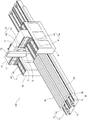
The invention discloses a CNC planer type milling machine with two automatic exchange working tables and capable of multiplying strokes relatively, which comprises: a machine table; two working sliding tables which are arranged on the machine table in a sliding way; the first X-axis driving device is arranged between the machine table and one of the working sliding tables; the second X-axis driving device is arranged between the machine table and the other working sliding table; two vertical walls respectively arranged at two sides of the machine platform; a beam crossing the machine platform and arranged on the two vertical walls in a sliding connection manner; the third X-axis driving device is arranged between the two vertical walls and the cross beam; the machining main shaft is arranged on the cross beam and can perform reciprocating displacement in the Y-axis direction and the Z-axis direction relative to the cross beam; the two work sliding tables or one of the two work sliding tables can be close to or far away from the machining main shaft in the X-axis direction at the same time, and the two work sliding tables can alternately carry the workpiece to be machined to the machining main shaft for machining or conveying out, so that the machining efficiency is improved, and the two work sliding tables can carry the large workpiece to be machined together for machining.
Description
Technical Field
The invention relates to the technical field of milling machines, in particular to a CNC planer type milling machine with two automatic exchange working tables and capable of multiplying strokes relatively.
Background
In response to different processing requirements, various types of metal processing machines such as milling machines, grinding machines, lathes, drilling machines, and honing machines have been developed, and these different types of metal processing machines usually have different structural designs to meet the processing requirements, so that they cannot be concluded from the general theory.
Please refer to patent 095130260 in taiwan for "dual-workbench machining center", fig. 1 and 2 (hereinafter referred to as the conventional cases), wherein fig. 1 and 2 are fig. 5 and 3 of the original drawings of the conventional cases, and the numbers marked on fig. 1 and 2 are rearranged and are different from the original numbers marked on the conventional cases, as shown in fig. 1 and 2, although the time for waiting for machining of the first workpiece 961 and the second workpiece 971 is shortened by using the first workbench 96 and the second workbench 97 and the arrangement of the partition plate 98 is used to prevent the splashed chips from falling on the first workpiece 961 and the second workpiece 971, the conventional cases of machining small workpieces can improve the machining quality and efficiency, however, when the present invention is applied to machining large workpieces, the load of the first workbench 96 or the second workbench 97 becomes large when carrying large workpieces, the displacement speed of the first workbench 96 and the second workbench 97 is greatly reduced, and the support seat 91 is designed to be fixed and cannot be displaced, so that the tool apron 95 of the head unit 94 can only be displaced left and right by the driving of the horizontal driving set 92, and cannot be displaced back and forth to be close to or far away from the first workbench 96 or the second workbench 97 in the same axial direction, the time required for the first workpiece 961 or the second workpiece 971 to be displaced to the position below the tool apron 95 cannot be increased, the processing efficiency cannot be improved, and in addition, due to the arrangement of the partition plate 98, the first workbench 96 and the second workbench 97 cannot be used for bearing larger workpieces together, so that the conventional scheme is only suitable for processing small workpieces and cannot be suitable for large workpieces, and the application range of the conventional scheme is limited.
In view of the above, in order to solve the problems of the prior art, such as the conventional method is not suitable for machining large-sized workpieces and the machining efficiency is low, the present inventors have made extensive studies, and have continued to design and improve the present invention, which finally achieves the following creation objectives.
Disclosure of Invention
The present invention provides a CNC planer type milling machine with two automatic exchange working tables capable of doubling the stroke relatively, which allows two or one of the working sliding tables and a processing spindle mounted on a cross beam to be close to or away from each other in the X-axis direction simultaneously, and the two working sliding tables can alternately carry a workpiece to be processed to the processing spindle for processing or carrying out, thereby shortening the displacement time required by the workpiece to be processed and the processing spindle meeting at the processing position, and improving the processing efficiency.
The present invention provides a CNC planer type milling machine with two automatic exchange working tables capable of doubling the stroke relatively, which can make the two working sliding tables move synchronously to carry larger workpieces to be processed for processing, or make the two working sliding tables carry smaller workpieces to be processed respectively for processing alternately, thereby making the scheduling of processing more flexible.
Based on the above, the present invention mainly adopts the following technical means to achieve the above object.
A CNC planer milling machine with two automatic exchange working tables and capable of multiplying strokes relatively comprises: a machine table; the two work sliding tables are arranged on the machine table in a sliding manner and comprise a first work sliding table and a second work sliding table; the first X-axis driving device is arranged between the machine table and the first working sliding table and used for driving the first working sliding table to carry out X-axis reciprocating displacement along the machine table; the second X-axis driving device is arranged between the machine table and the second working sliding table and used for driving the second working sliding table to carry out X-axis reciprocating displacement along the machine table; two vertical walls respectively arranged at two sides of the machine platform; a beam crossing the machine platform and arranged on the two vertical walls in a sliding connection manner; the third X-axis driving device is arranged between the two vertical walls and the cross beam and is used for driving the cross beam to carry out X-axis reciprocating displacement along the vertical walls; and the processing main shaft is arranged on the cross beam and can perform reciprocating displacement in the Y-axis direction and the Z-axis direction relative to the cross beam.
Furthermore, the first X-axis driving device has at least one first screw and at least one first nut for generating rotational power, the first screw is disposed on the machine platform, and the first nut is fixedly disposed on the first working sliding table and is in threaded connection with the first screw, so that when the first screw rotates in the forward direction and in the reverse direction, the first nut drives the first working sliding table to perform X-axis reciprocating displacement.
Furthermore, the second X-axis driving device has at least one second screw and at least one second nut for generating rotational power, the second screw is disposed on the machine platform, and the second nut is fixedly disposed on the second sliding table and is in threaded connection with the second screw, so that when the second screw rotates in the forward and reverse directions, the second nut drives the second sliding table to perform X-axis reciprocating displacement.
Furthermore, the third X-axis driving device has two X-axis magnetic stator tracks respectively disposed on the top surfaces of the vertical walls and two X-axis power sensing devices respectively disposed at the bottom of the beam corresponding to the positions of the X-axis magnetic stator tracks, so that the X-axis power sensing devices move along the X-axis magnetic stator tracks to drive the beam to perform reciprocating displacement in the X-axis direction.
Furthermore, the third X-axis driving device has two third screws respectively disposed on the top surfaces of the vertical walls for generating rotational power and two third nuts respectively disposed at the bottom of the cross beam corresponding to the positions of the third screws, and the third nuts are screwed with the third screws, so that when the third screws rotate in the forward and reverse directions, the third nuts drive the cross beam to perform X-axis reciprocating displacement.
Furthermore, the processing spindle is provided with a Y-axis sliding seat, a Z-axis sliding seat, a spindle head, a Y-axis driving device and a Z-axis driving device; this Y axle slide sliding connection is in this crossbeam one side, and this Z axle slide sliding connection is on this Y axle slide, and this spindle head sets up on this Z axle slide, and this Y axle drive arrangement sets up between this crossbeam and this Y axle slide for drive this Y axle slide carries out the reciprocating displacement of Y axial along this crossbeam, and this Z axle drive arrangement sets up between this Y axle slide and this Z axle slide, is used for driving this Z axle slide to carry out the reciprocating displacement of Z axial along this Y axle slide.
Furthermore, the Y-axis driving device is provided with a Y-axis magnetic stator track arranged on one side of the beam and a Y-axis power induction device arranged on the Y-axis sliding seat and corresponding to the position of the Y-axis magnetic stator track, so that the Y-axis power induction device moves along the Y-axis magnetic stator track to drive the Y-axis sliding seat to perform reciprocating displacement in the Y-axis direction.
Furthermore, the Y-axis driving device is provided with a Y-axis screw rod arranged on one side of the beam and a Y-axis nut which is arranged on the Y-axis sliding seat and corresponds to the position of the Y-axis screw rod and is in threaded connection with the Y-axis screw rod, so that when the Y-axis screw rod rotates forwards and backwards, the Y-axis sliding seat can be driven to carry out reciprocating displacement in the Y-axis direction.
Furthermore, the Z-axis driving device is provided with a Z-axis power induction device arranged on one side of the Y-axis sliding seat and a Z-axis magnetic stator track which is arranged on the Z-axis sliding seat and corresponds to the Z-axis power induction device, so that the Z-axis power induction device and the Z-axis magnetic stator track mutually induce to move, and the Z-axis sliding seat is driven to carry out reciprocating displacement in the Z-axis direction.
Furthermore, the Z-axis driving device is provided with a Z-axis nut fixedly arranged on one side of the Y-axis sliding seat and a Z-axis screw rod which is arranged on the Z-axis sliding seat and is in threaded connection with the Z-axis nut, so that when the Z-axis screw rod rotates forwards and backwards, the Z-axis screw rod can also move up and down simultaneously to drive the Z-axis sliding seat to perform reciprocating displacement in the Z-axis direction.
By adopting the technical means, the invention adopts the mechanism design of the machine table, the work sliding table, the first X-axis driving device, the second X-axis driving device, the vertical wall, the cross beam, the third X-axis driving device and the processing main shaft, wherein the work sliding tables are respectively arranged on the machine table in a sliding way and comprise a first work sliding table and a second work sliding table; the first X-axis driving device is arranged between the machine table and the first working sliding table and used for driving the first working sliding table to carry out X-axis reciprocating displacement along the machine table; the second X-axis driving device is arranged between the machine table and the second working sliding table and used for driving the second working sliding table to carry out X-axis reciprocating displacement along the machine table; the two vertical walls are respectively arranged at two sides of the machine platform; the cross beam crosses the machine platform and is arranged on the two vertical walls in a sliding connection mode; the third X-axis driving device is arranged between the two vertical walls and the cross beam and is used for driving the cross beam to carry out X-axis reciprocating displacement along the vertical walls; the processing main shaft is arranged on the cross beam and can perform reciprocating displacement in the Y-axis direction and the Z-axis direction relative to the cross beam; therefore, the two work sliding tables or one of the work sliding tables can be close to or far away from the processing main shaft in the X-axis direction simultaneously, and the two work sliding tables can alternately carry the workpiece to be processed to the processing main shaft for processing or carrying out, so that the displacement time required by the workpiece to be processed and the processing main shaft meeting at the processing position can be shortened, the two work sliding tables can synchronously displace to carry a larger workpiece to be processed for processing, or the two work sliding tables can respectively carry smaller workpieces to be processed for processing alternately, and the scheduling of the processing is more flexible, thereby improving the processing efficiency and being suitable for processing the workpieces to be processed with the common size or large workpieces to be processed.
Drawings
FIG. 1 is a schematic side view of a conventional planer type milling machine.
FIG. 2 is a front view of a conventional planer type milling machine.
Fig. 3 is a perspective view of a first preferred embodiment of the present invention.
Fig. 4 is another perspective view of the first preferred embodiment of the present invention.
FIG. 5 is a perspective view of a first preferred embodiment of the present invention for carrying a workpiece to be processed.
Fig. 6 to 9 are schematic top operation views of the processing flow of the embodiment shown in fig. 3.
FIG. 10 is a top view of a first preferred embodiment of the present invention for carrying a large workpiece to be processed.
Fig. 11 is a perspective view of a second preferred embodiment of the present invention.
Fig. 12 is a perspective view of the embodiment of fig. 9 from another perspective.
[ notation ] to show
The first preferred embodiment of the present invention
CNC planer type milling machine 100 capable of relatively multiplying stroke with two automatic workpiece table exchange functions
Machine table 10
First workpiece to be machined 21 and second workpiece to be machined 22
First X-axis drive 30
Third X-axis drive 60
X-axis magnetic stator track 61X-axis power induction device 62
Y-axis slide carriage 71Z-axis slide carriage 72
Y-axis driving device 74 of spindle head 73
Y-axis magnetic stator rail 741Y-axis power sensing device 742
Z-axis drive 75Z-axis magnetic stator track 751
Z-axis power sensing device 752
Second X-axis drive 80
The second preferred embodiment of the present invention
CNC planer type milling machine 200 capable of relatively multiplying stroke with two automatic workpiece table exchange functions
Machine table 10
First X-axis drive 30
Third X-axis drive 60
Y-axis slide carriage 71Z-axis slide carriage 72
Y-axis driving device 74 of spindle head 73
Y-axis screw 743Y-axis nut 744
Z-axis driving device 75Z-axis nut 753
Z-axis screw 754
Second X-axis drive 80
Horizontal driving set 92 of supporting seat 91
First work table 96 first work piece 961
Second work table 97 second work piece 971
A partition 98.
Detailed Description
To further understand and appreciate the features and characteristics of the present invention, the following embodiments are illustrated in the drawings:
referring to fig. 3 and 4, a CNC planer type milling machine 100 with two automatic exchange worktables and capable of doubling the stroke relatively provided by the first preferred embodiment of the present invention mainly includes a machine table 10, two working slide tables 20 and 201, a first X-axis driving device 30, a second X-axis driving device 80, two vertical walls 40, a cross beam 50, a third X-axis driving device 60 and a processing spindle 70, wherein:
the machine 10 can be stably placed on a floor (or a plane).
The two work sliding tables 20 and 201 are slidably disposed on the machine table 10 for fixing a workpiece to be processed, and each work sliding table 20 and 201 can independently perform reciprocating displacement on the machine table 10 or perform synchronous reciprocating displacement together, and includes a first work sliding table 20 and a second work sliding table 201.
The first X-axis driving device 30 is disposed between the machine table 10 and the first sliding table 20, and is configured to drive the first sliding table 20 to perform reciprocating displacement along the machine table 10 in the X-axis direction. In this embodiment, the first X-axis driving device 30 has at least one first screw 31 and at least one first nut 32, the first screw 31 is disposed on the machine table 10 for generating a rotation power, and the first nut 32 is fixedly disposed on the first working sliding table 20 and is screwed with the first screw 31, so that when the first screw 31 rotates in the forward and reverse directions, the first nut 32 drives the first working sliding table 20 to perform an X-axis reciprocating displacement.
The second X-axis driving device 80 is disposed between the machine table 10 and the second sliding table 201, and is configured to drive the second sliding table 201 to perform reciprocating displacement along the machine table 10 in the X-axis direction. In this embodiment, the second X-axis driving device 80 has at least one second screw 81 and at least one second nut 82, the second screw 81 is disposed on the machine table 10 for generating a rotation power, and the second nut 82 is fixedly disposed on the second sliding table 201 and is screwed with the second screw 81, so that when the second screw 81 rotates in the forward and reverse directions, the second nut 82 drives the second sliding table 201 to perform a reciprocating displacement in the X-axis direction.
The two vertical walls 40 are respectively disposed on two sides of the machine 10.
The beam 50 is disposed on the two vertical walls 40 across the machine 10 in a sliding manner.
The third X-axis driving device 60 is disposed between the two vertical walls 40 and the cross beam 50, and is used for driving the cross beam 50 to perform reciprocating displacement along the vertical wall 40 in the X-axis direction. In the present embodiment, the third X-axis driving device 60 has two X-axis magnetic stator tracks (linear motor tracks) 61 respectively disposed on the top surfaces of the vertical walls 40 and two X-axis power sensing devices 62 respectively disposed at the bottom of the cross beam 50 corresponding to the positions of the X-axis magnetic stator tracks 61, so that the X-axis power sensing devices 62 move along the X-axis magnetic stator tracks 61 to drive the cross beam 20 to perform the reciprocating displacement in the X-axis direction.
The processing spindle 70 is disposed on the cross beam 50 and can perform reciprocating displacement in the Y-axis direction and the Z-axis direction with respect to the cross beam 50, so as to process the workpieces on the first work sliding table 20 and the second work sliding table 201. In the present embodiment, the machining spindle 70 has a Y-axis slide 71, a Z-axis slide 72, a spindle head 73, a Y-axis driving device 74 and a Z-axis driving device 75; the Y-axis slide carriage 71 is slidably connected to one side of the cross beam 50 and located above the first slide table 20 or the second slide table 201, the Z-axis slide carriage 72 is slidably connected to the Y-axis slide carriage 71, the main spindle head 73 is disposed on the Z-axis slide carriage 72 for processing a workpiece to be processed, the Y-axis driving device 74 is disposed between the cross beam 50 and the Y-axis slide carriage 71 for driving the Y-axis slide carriage 71 to perform a reciprocating displacement along the Y-axis direction of the cross beam 50, in this embodiment, the Y-axis driving device 74 has a Y-axis magnetic stator rail 741 disposed on one side of the cross beam 50 and a Y-axis power sensing device 742 disposed on the Y-axis slide carriage 71 and corresponding to the Y-axis magnetic stator rail 741, so that the Y-axis magnetic stator rail 741 is moved by the Y-axis power sensing device 742 to drive the Y-axis slide carriage 71 to perform a reciprocating displacement along the Y-axis direction, the Z-axis driving device 75 is disposed between the Y-axis slide carriage 71 and the Z-axis slide carriage 72, in this embodiment, the Z-axis driving device 75 has a Z-axis power sensing device 752 disposed at one side of the Y-axis slide carriage 71 and a Z-axis magnetic stator track 751 disposed on the Z-axis slide carriage 72 and corresponding to the Z-axis power sensing device 752, so that the Z-axis magnetic stator track 752 and the Z-axis power sensing device 752 are induced to move to drive the Z-axis slide carriage 72 to perform Z-axis reciprocating displacement.
Therefore, the above description is the description of each component of the CNC planer type milling machine 100 with two automatic exchange tables and capable of relatively multiplying the stroke and the assembling method thereof provided by the first preferred embodiment of the present invention, and then the features thereof are described as follows:
referring to fig. 5 to 7, the first work slide table 20 and the second work slide table 201 may be respectively provided with two first workpieces to be machined 21 and two second workpieces to be machined 22, the first X-axis driving device 30 may drive the first work slide table 20 to displace along the X-axis of the machine 10 toward the cross beam 50, the third X-axis driving device 60 may drive the cross beam 50 to displace along the X-axis of the two vertical walls 40 toward the first work slide table 20, and at the same time as the cross beam 50 displaces, the processing spindle 70 can simultaneously move along the Y-axis of the cross beam 50 to a position right above the first work slide 20, so that the first workpiece 21 to be processed on the first work slide 20 can quickly move to a position below the processing spindle 70, thereby achieving the speed of twice speed displacement to shorten the time of the first workpiece 21 to be processed moving to the lower part of the processing main shaft 70, thereby improving the processing efficiency.
Referring to fig. 8 and 9, when the first workpiece to be machined 21 on the first sliding table 20 is machined, the first sliding table 20 retracts to its original position along the X-axis of the machine 10, the second sliding table 201 simultaneously displaces toward the cross beam 50 along the X-axis of the machine 10, and while the second sliding table 201 displaces, the machining spindle 70 also simultaneously displaces to a position right above the second sliding table 201 along the Y-axis of the cross beam 50, and then the machining spindle 70 machines the second workpiece to be machined 22 on the second sliding table 201; after the second workpiece 22 to be machined is machined, the second sliding table 201 retracts to its original position along the X-axis of the machine 10, the first sliding table 20 carries a new first workpiece 21 to be machined along the X-axis of the machine 10 and displaces toward the cross beam 50, while the first sliding table 20 displaces, the machining spindle 70 also displaces to a position right above the first sliding table 20 along the Y-axis of the cross beam 50, and the new first workpiece 21 to be machined is machined by the machining spindle 70; in this way, the first work slide table 20 and the second work slide table 201 can alternately carry the workpiece to be machined to move to the position below the machining spindle 70 for machining, and it is not necessary to carry another workpiece to be machined to the position below the machining spindle after the workpiece to be machined returns to the original position for machining, thereby effectively improving the machining efficiency.
Referring to fig. 10 again, for the processing of the large workpiece 23 to be processed, the first work slide table 20 and the second work slide table 201 of the present embodiment can be synchronously displaced by the actions of the first X-axis driving device 30 and the second X-axis driving device 80, the large workpiece 23 to be processed can straddle the first work slide table 20 and the second work slide table 201, and the first work slide table 20 and the second work slide table 201 synchronously carry the large workpiece 23 to be processed to be displaced along the X-axis of the machine 10 toward the cross beam 50, and the processing spindle 70 processes the large workpiece 23, so that the present embodiment is applicable to the processing of workpieces to be processed with general sizes, and also applicable to the processing of large workpieces to be processed, and has a wider utility.
Referring to fig. 11 and fig. 12, a CNC planer type milling machine 200 with two automatic exchange worktables and capable of doubling the stroke provided by the second preferred embodiment of the present invention mainly includes a machine table 10, a first work slide table 20, a second work slide table 201, a first X-axis driving device 30, a second X-axis driving device 80, two vertical walls 40, a cross beam 50, a third X-axis driving device 60 and a processing spindle 70, which are the same as the above embodiments, and the main differences between them are:
in this embodiment, the third X-axis driving device 60 has two third screws 63 respectively disposed on the top surfaces of the vertical walls 40 and two third nuts 62 respectively disposed at the bottom of the cross beam 50 corresponding to the positions of the third screws 63, the third screws 63 are used for generating rotational power, and the third nuts 64 are screwed with the third screws 63, so that when the third screws 63 rotate in the forward and reverse directions, the third nuts 64 drive the cross beam 50 to perform reciprocating displacement in the X-axis direction.
In the present embodiment, the machining spindle 70 also has a Y-axis slide 71, a Z-axis slide 72, a spindle head 73, a Y-axis driving device 74 and a Z-axis driving device 75; the main differences from the previous embodiment are: in this embodiment, the Y-axis driving device 74 has a Y-axis screw 743 installed on one side of the beam 50 and a Y-axis nut 744 installed on the Y-axis slide carriage 71 corresponding to the Y-axis screw 743 and screwed with the Y-axis screw 743, so that when the Y-axis screw 743 rotates in the forward direction and in the reverse direction, the Y-axis slide carriage 71 can be driven to perform reciprocating displacement in the Y-axis direction, and the Z-axis driving device 75 has a Z-axis nut 753 fixed on one side of the Y-axis slide carriage 71 and a Z-axis screw 754 installed on the Z-axis slide carriage 72 and screwed with the Z-axis nut 753, so that when the Z-axis screw 754 rotates in the forward direction and in the reverse direction, the Z-axis slide carriage 72 can be driven to perform reciprocating displacement in the Z-axis direction by moving up and down at the same time.
Therefore, the present invention can achieve the effect of simultaneously moving the first sliding table 20 or the second sliding table 201 and the cross beam 50 in the dual X-axis direction, and can replace the combination of the expensive magnetic stator track and the power induction device by the combination of the relatively cheap screw and nut, so as to achieve the effect of reducing the manufacturing cost.
The above disclosure is only for the purpose of illustrating the preferred embodiments of the present invention and is not intended to limit the scope of the present invention, and all equivalent variations of those skilled in the art according to the present invention should fall within the scope of the present invention.
Claims (10)
Priority Applications (1)
| Application Number | Priority Date | Filing Date | Title |
|---|---|---|---|
| CN201811300665.9A CN111136307A (en) | 2018-11-02 | 2018-11-02 | CNC planer type milling machine with two automatic exchange working tables and capable of multiplying stroke relatively |
Applications Claiming Priority (1)
| Application Number | Priority Date | Filing Date | Title |
|---|---|---|---|
| CN201811300665.9A CN111136307A (en) | 2018-11-02 | 2018-11-02 | CNC planer type milling machine with two automatic exchange working tables and capable of multiplying stroke relatively |
Publications (1)
| Publication Number | Publication Date |
|---|---|
| CN111136307A true CN111136307A (en) | 2020-05-12 |
Family
ID=70515403
Family Applications (1)
| Application Number | Title | Priority Date | Filing Date |
|---|---|---|---|
| CN201811300665.9A Withdrawn CN111136307A (en) | 2018-11-02 | 2018-11-02 | CNC planer type milling machine with two automatic exchange working tables and capable of multiplying stroke relatively |
Country Status (1)
| Country | Link |
|---|---|
| CN (1) | CN111136307A (en) |
Cited By (2)
| Publication number | Priority date | Publication date | Assignee | Title |
|---|---|---|---|---|
| CN111842997A (en) * | 2020-06-18 | 2020-10-30 | 诸暨信胜机械制造有限公司 | Numerical control planer type milling machine for machining ultra-long parts and machining method |
| CN115090542A (en) * | 2022-06-28 | 2022-09-23 | 征图新视(江苏)科技股份有限公司 | Double-flow-passage film product detection equipment |
-
2018
- 2018-11-02 CN CN201811300665.9A patent/CN111136307A/en not_active Withdrawn
Cited By (2)
| Publication number | Priority date | Publication date | Assignee | Title |
|---|---|---|---|---|
| CN111842997A (en) * | 2020-06-18 | 2020-10-30 | 诸暨信胜机械制造有限公司 | Numerical control planer type milling machine for machining ultra-long parts and machining method |
| CN115090542A (en) * | 2022-06-28 | 2022-09-23 | 征图新视(江苏)科技股份有限公司 | Double-flow-passage film product detection equipment |
Similar Documents
| Publication | Publication Date | Title |
|---|---|---|
| CN205464494U (en) | Many spindle processing equipment | |
| CN103878592B (en) | Lathe | |
| WO2020207351A1 (en) | Efficient horizontal machining central machine tool having double main shafts and double work tables | |
| CN103878590A (en) | Machine tool | |
| TWI477350B (en) | Feeding device and machine tool using the same | |
| JP6071862B2 (en) | Metal processing method | |
| CN204397367U (en) | A kind of dynamic post and beam gantry Five-axis NC Machining Center | |
| CN110814788A (en) | Numerical control machine tool with planetary exchange workbench | |
| CN202824839U (en) | Mechanical type upright internal broaching machine | |
| CN205614068U (en) | Machine tool | |
| CN110000415A (en) | A kind of high-speed milling machine | |
| CN201109033Y (en) | A processing jig | |
| CN210116311U (en) | Five numerical control cnc engraving and milling machines | |
| CN106926070A (en) | A kind of tip tap-grinding machine | |
| CN207577510U (en) | High precision CNC milling machine | |
| CN102658374B (en) | Two-box four-shaft multi-functional numerical control machine tool | |
| TWI505905B (en) | Machining method for metallic workpiece | |
| TW201701988A (en) | Dual-head multipurpose machine tool having stable structure and enhancing machine precision, prolonging service life of the machine, and effectively enhancing machining efficiency | |
| CN211440360U (en) | Numerical control multifunctional five-axis machining center | |
| TWI661886B (en) | Relatively double stroke CNC gantry milling machine with two automatic exchange tables | |
| TW202033306A (en) | Double-efficiency dual-spindle gantry processing machine with two automatic exchange work sliding table in which two spindle heads can process workpieces to be processed on two work sliding tables at the same time | |
| CN203818255U (en) | Main machine tool subassembly for numerical control machining center | |
| CN115922445A (en) | A Gantry Flexible Multi-Axis Machining Center Platform and Reconfiguration Combination Method | |
| CN211072873U (en) | A new type of high-efficiency multi-head and multi-axis simultaneous machining machine tool | |
| CN114473742A (en) | Grinding machine for processing grooved parts |
Legal Events
| Date | Code | Title | Description |
|---|---|---|---|
| PB01 | Publication | ||
| PB01 | Publication | ||
| SE01 | Entry into force of request for substantive examination | ||
| SE01 | Entry into force of request for substantive examination | ||
| WW01 | Invention patent application withdrawn after publication | ||
| WW01 | Invention patent application withdrawn after publication |
Application publication date: 20200512 |