CN111135699A - Tray device for countercurrent spray tower and countercurrent spray tower - Google Patents

Tray device for countercurrent spray tower and countercurrent spray tower Download PDF

Info

Publication number
CN111135699A
CN111135699A CN202010219032.6A CN202010219032A CN111135699A CN 111135699 A CN111135699 A CN 111135699A CN 202010219032 A CN202010219032 A CN 202010219032A CN 111135699 A CN111135699 A CN 111135699A
Authority
CN
China
Prior art keywords
spray tower
tray
counter
base
tray device
Prior art date
Legal status (The legal status is an assumption and is not a legal conclusion. Google has not performed a legal analysis and makes no representation as to the accuracy of the status listed.)
Granted
Application number
CN202010219032.6A
Other languages
Chinese (zh)
Other versions
CN111135699B (en
Inventor
尤江英
彭飞荣
葛朝晖
郑飞
Current Assignee (The listed assignees may be inaccurate. Google has not performed a legal analysis and makes no representation or warranty as to the accuracy of the list.)
China Construction Power And Environment Engineering Co ltd
Original Assignee
China Construction Power And Environment Engineering Co ltd
Priority date (The priority date is an assumption and is not a legal conclusion. Google has not performed a legal analysis and makes no representation as to the accuracy of the date listed.)
Filing date
Publication date
Application filed by China Construction Power And Environment Engineering Co ltd filed Critical China Construction Power And Environment Engineering Co ltd
Priority to CN202010219032.6A priority Critical patent/CN111135699B/en
Publication of CN111135699A publication Critical patent/CN111135699A/en
Application granted granted Critical
Publication of CN111135699B publication Critical patent/CN111135699B/en
Active legal-status Critical Current
Anticipated expiration legal-status Critical

Links

Images

Classifications

    • B—PERFORMING OPERATIONS; TRANSPORTING
    • B01—PHYSICAL OR CHEMICAL PROCESSES OR APPARATUS IN GENERAL
    • B01D—SEPARATION
    • B01D53/00—Separation of gases or vapours; Recovering vapours of volatile solvents from gases; Chemical or biological purification of waste gases, e.g. engine exhaust gases, smoke, fumes, flue gases, aerosols
    • B01D53/34—Chemical or biological purification of waste gases
    • B01D53/74—General processes for purification of waste gases; Apparatus or devices specially adapted therefor
    • B01D53/80—Semi-solid phase processes, i.e. by using slurries
    • B—PERFORMING OPERATIONS; TRANSPORTING
    • B01—PHYSICAL OR CHEMICAL PROCESSES OR APPARATUS IN GENERAL
    • B01D—SEPARATION
    • B01D53/00—Separation of gases or vapours; Recovering vapours of volatile solvents from gases; Chemical or biological purification of waste gases, e.g. engine exhaust gases, smoke, fumes, flue gases, aerosols
    • B01D53/34—Chemical or biological purification of waste gases
    • B01D53/46—Removing components of defined structure
    • B01D53/48—Sulfur compounds
    • B01D53/50—Sulfur oxides
    • B01D53/501—Sulfur oxides by treating the gases with a solution or a suspension of an alkali or earth-alkali or ammonium compound
    • B01D53/502—Sulfur oxides by treating the gases with a solution or a suspension of an alkali or earth-alkali or ammonium compound characterised by a specific solution or suspension
    • B—PERFORMING OPERATIONS; TRANSPORTING
    • B01—PHYSICAL OR CHEMICAL PROCESSES OR APPARATUS IN GENERAL
    • B01D—SEPARATION
    • B01D53/00—Separation of gases or vapours; Recovering vapours of volatile solvents from gases; Chemical or biological purification of waste gases, e.g. engine exhaust gases, smoke, fumes, flue gases, aerosols
    • B01D53/34—Chemical or biological purification of waste gases
    • B01D53/46—Removing components of defined structure
    • B01D53/48—Sulfur compounds
    • B01D53/50—Sulfur oxides
    • B01D53/501—Sulfur oxides by treating the gases with a solution or a suspension of an alkali or earth-alkali or ammonium compound
    • B01D53/504—Sulfur oxides by treating the gases with a solution or a suspension of an alkali or earth-alkali or ammonium compound characterised by a specific device
    • B—PERFORMING OPERATIONS; TRANSPORTING
    • B01—PHYSICAL OR CHEMICAL PROCESSES OR APPARATUS IN GENERAL
    • B01D—SEPARATION
    • B01D53/00—Separation of gases or vapours; Recovering vapours of volatile solvents from gases; Chemical or biological purification of waste gases, e.g. engine exhaust gases, smoke, fumes, flue gases, aerosols
    • B01D53/34—Chemical or biological purification of waste gases
    • B01D53/46—Removing components of defined structure
    • B01D53/54—Nitrogen compounds
    • B01D53/56—Nitrogen oxides
    • B—PERFORMING OPERATIONS; TRANSPORTING
    • B01—PHYSICAL OR CHEMICAL PROCESSES OR APPARATUS IN GENERAL
    • B01D—SEPARATION
    • B01D2258/00—Sources of waste gases
    • B01D2258/02—Other waste gases
    • B01D2258/0283—Flue gases

Landscapes

  • Engineering & Computer Science (AREA)
  • Chemical & Material Sciences (AREA)
  • Environmental & Geological Engineering (AREA)
  • Health & Medical Sciences (AREA)
  • Biomedical Technology (AREA)
  • Analytical Chemistry (AREA)
  • General Chemical & Material Sciences (AREA)
  • Oil, Petroleum & Natural Gas (AREA)
  • Chemical Kinetics & Catalysis (AREA)
  • Treating Waste Gases (AREA)

Abstract

本发明提供了一种逆流喷淋塔用托盘装置及逆流喷淋塔,其中逆流喷淋塔用托盘装置,包括至少一多孔板,其特征在于,所述多孔板包括基部以及设置在所述基部上的沿所述逆流喷淋塔高度方向延伸的凸部;在所述基部上设置有通孔;所述凸部内部为凹腔,在所述凹腔内设置有与所述凹腔匹配的用于固定所述多孔板的支撑结构。该托盘装置与支撑结构具有凹凸相匹配的特点,可以最大程度减少托盘结构的紧固连接件数量,降低托盘加工和投资成本,保证有害气体净化系统的安全稳定运行。同时提供应用该托盘装置的逆流喷淋塔。
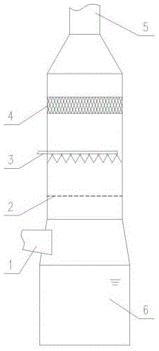
Figure 202010219032

The invention provides a tray device for a counter-current spray tower and a counter-current spray tower, wherein the tray device for a counter-current spray tower includes at least one perforated plate, characterized in that the perforated plate includes a base and a a convex part on the base part extending along the height direction of the countercurrent spray tower; a through hole is arranged on the base part; the interior of the convex part is a concave cavity, and a cavity matching with the concave cavity is arranged in the concave cavity the support structure for fixing the perforated plate. The tray device and the supporting structure have the characteristics of matching the concavity and convexity, which can minimize the number of fastening connectors of the tray structure, reduce the processing and investment cost of the tray, and ensure the safe and stable operation of the harmful gas purification system. At the same time, a countercurrent spray tower using the tray device is provided.

Figure 202010219032

Description

Tray device for countercurrent spray tower and countercurrent spray tower
Technical Field
The invention belongs to the field of air pollution prevention and control, and particularly relates to a tray device for a countercurrent spray tower and the countercurrent spray tower.
Background
With the release and execution of the "emission standard of atmospheric pollutants for thermal power plants" (GB13223-2011) and the requirements of the coal-electricity energy-saving emission-reduction upgrading and reconstruction action plan (2014-2020),: the emission concentration of the atmospheric pollutants of the newly-built coal-fired power generating unit basically reaches the emission limit value of the gas turbine unit (namely under the condition that the reference oxygen content is 6 percent, the emission concentrations of smoke dust, sulfur dioxide and nitrogen oxides are respectively not higher than 10 mg/cubic meter, 35 mg/cubic meter and 50 mg/cubic meter). In order to adapt to increasingly strict emission standards of sulfur dioxide in flue gas in China, a plurality of effect-improving measures are developed for a wet desulphurization system.
At present when utilizing desulfurization equipment such as adverse current spray column to carry out desulfurization treatment to flue gas, generally install the trompil tray in the absorption tower that sprays against the current, thereby the flue gas upwards passes the tray trompil and contacts with the spun thick liquid of layer that sprays, and the thick liquid is after fully contact reaction with the flue gas, gets rid of the sulfur dioxide in the flue gas after, passes the tray trompil downwards, flows into the thick liquid pond that is located desulfurization absorption tower bottom. Meanwhile, the tray can rectify the flue gas, the uniformity of the distribution of the flue gas is improved, and a liquid holding layer with a certain thickness can be formed on the tray, so that the gas-liquid contact reaction time is prolonged, and the desulfurization efficiency can be effectively improved. China Hua electric science corporation limited has studied a fixing device (CN 209646213U) of tray structure, but this fixing device accessory is many, and whole absorption tower assembly quantity is many, and is easy not hard up in the operation in-process and drops, and small-size part gets into the circulating pump body along with the thick liquid to greatly increased the risk of destroying the circulating pump, increased desulfurization system operation and maintained the input. The Tang environmental industry group company Limited researches the shape of the opening of the tray (CN 206198999U), but the non-circular special-shaped holes increase the machining difficulty and improve the cost of the tray; and the supporting structure of the tray device is not considered in the research, so that the engineering applicability of the tray device is influenced.
Therefore, in view of the current situation, a tray device capable of effectively improving the operation efficiency and stability of the countercurrent spray absorption tower is urgently needed to be developed, and the requirements of practical use are met while the safe operation of a desulfurization system is ensured.
Disclosure of Invention
Aiming at the defects of the tray device for the existing countercurrent spray tower, the invention aims to provide the tray device for the countercurrent spray tower and the countercurrent spray tower applying the tray device, which can effectively improve the desulfurization efficiency and ensure the safe and stable operation of a desulfurization system.
In order to achieve the purpose, the invention adopts the specific technical scheme that:
a tray device for a countercurrent spray tower comprises at least one porous plate, and is characterized in that the porous plate comprises a base and a convex part which is arranged on the base and extends along the height direction of the countercurrent spray tower; a through hole is arranged on the base; and a concave cavity is arranged in the convex part, and a supporting structure which is matched with the concave cavity and used for fixing the porous plate is arranged in the concave cavity.
The convex parts are distributed on the base part in a strip shape, and the distance between the convex parts is selected from 300-2500 mm.
The supporting structure is rectangular section steel.
The base and the projection are of an integral structure.
The diameter of the opening of the through hole on the base is selected from 20-70 mm. The diameter in each through hole is uniform.
A counter-flow spray tower comprising, arranged in series along a flow path of a noxious gas: a gas inlet and at least one spray level, wherein a tray device for a counter-current spray tower according to any one of claims 1 to 6 is arranged between the gas inlet and the spray level and/or each spray level. Furthermore, the countercurrent spray tower discharges harmful gas from bottom to top, and in the process of rising the harmful gas, the absorbent is sprayed out through the spray layer nozzles and is discharged after contacting and reacting with the harmful gas from top to bottom.
Furthermore, the countercurrent spray tower with the tray device also comprises a supporting structure arranged below the tray body along the inner wall of the countercurrent spray tower.
Furthermore, the supporting structure below the tray and the tray structure have the characteristic of concave-convex matching.
Further, the distance between the supporting structures below the tray is selected from 300-2500 mm.
Through the technical scheme, harmful gas flows in from the inlet of the countercurrent spray tower, sequentially flows upwards through the tray device, the spray layer and the demisting layer, and finally flows out from the outlet of the countercurrent spray tower. Harmful gas absorbent liquid in the countercurrent spray tower is sprayed out through the spray layer, flows through the tray device, falls into the collection pool and is finally discharged. Through adopting and having unsmooth assorted bearing structure with the tray structure, reach the tray device of circular multiple-pass pore structure, carry out the modularization equipment back, guarantee the spray column steady operation against current.
Drawings
Fig. 1 is a schematic structural diagram of a counter-flow spray tower according to an embodiment of the present invention.
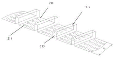
FIG. 2 is a schematic diagram of a three-dimensional structure of a multi-well plate with a single sheet width M according to an embodiment of the present invention.
Fig. 3 is a side view of a partial structure of a tray device according to an embodiment of the invention.
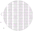
Fig. 4 is a schematic top view of a portion of a tray apparatus according to an embodiment of the invention.
Description of reference numerals: 1-a gas inlet; 2-a tray device; 21-a perforated plate; 211. a base; 212. a convex portion; 213. a concave cavity; 214. a through hole; 22. a support structure; 3-spraying layer; 4-a demister; 5-a gas outlet; 6-collecting pool.
Detailed Description
The technical solution in the embodiments of the present invention will be clearly and completely described below with reference to the accompanying drawings in the embodiments of the present invention.
As shown in fig. 1, in one embodiment, there is provided a counter-flow spray tower comprising, arranged in sequence along a harmful gas flow path: the gas inlet 1, the tray device 2, the spraying layer 3, the demister 4 and the gas outlet 5, and the collecting tank 6 is arranged at the lower part in the countercurrent spraying tower. Wherein, tray device 2 includes a perforated plate 21 and with the unsmooth assorted bearing structure 22 of tray structure, its interval of this bearing structure is selected from between 300~2500mm, welded fastening between bearing structure 22 and the tower body, perforated plate 21 places on bearing structure.
The porous plate 21 includes a base 211 and a convex portion 212 provided on the base and extending in the height direction of the counter current spray tower; the base 211 and the protrusion 212 may be integrally formed by bending. The convex portion has a concave cavity 213 therein. The perforated plate 21 is provided with a plurality of circular through holes 214, and the diameter of the holes is selected from 20-70 mm;
the aperture ratio of the through holes on the porous plate is selected from 0.2-0.5. Within the range, the slurry descending effect can be effectively kept, and the tray is prevented from flooding.
As shown in fig. 2 and 4, the tray device is formed by splicing a plurality of perforated plates. The width M of the porous plate is selected from 200-2000 mm.
The porous plate is made of alloy steel or non-metal wear-resistant material. The material is alloy steel, for example, stainless steel, and can be processed by punching or drilling when processing a through hole. The material is a non-metal wear-resistant material, such as a glass fiber reinforced plastic composite material, and the through holes can be integrally formed through a die pressing process or drilled after machining.
The counter-current spray tower and the tray device applied to the counter-current spray tower described in the above embodiments can be used in a wet desulphurization system which is used in large quantities in China, and the performance of the counter-current spray tower is improved. The porous tray adopts the design of circular through-hole, can furthest reduce the tray processing and the construction process degree of difficulty, adopts unsmooth assorted tray structure with bearing structure, can reduce the fastening connection spare of tray structure, guarantees the operation of system safety and stability.
As shown in fig. 3, the supporting structure under the tray has the concave-convex matching characteristic with the tray structure.
In addition, the distance between the supporting structures below the tray is selected from 300-2500 mm.
The supporting structure below the tray generally adopts rectangular section steel as a supporting beam, and if other shape section steel is adopted, the tray structure is adjusted correspondingly to the supporting structure, so that the characteristics of concave-convex matching between the tray structure and the supporting structure are ensured.
In addition, as shown in FIG. 3, the height N of the rectangular section steel of the supporting structure is selected from 150 to 500 mm.
In addition, the tray device of the countercurrent spray tower and the supporting structure adopt the concave-convex matching characteristic, and the bottom surface of the supporting structure and the perforated area of the tray device are kept on the same horizontal plane.
In order to ensure the enough strength of the bearing area of the tray, the area of the convex area of the tray device matched with the supporting beam is not drilled.
This kind of structural design can form when a large amount of thick liquids flow through the tray and keep better thick liquids descending effect, forms the liquid layer of holding of certain thickness that supplies flue gas and thick liquids abundant contact reaction, under the dual function of holding liquid layer weight and tray device dead weight, can with a supporting beam phase-match, reduces the use of fastener. Aiming at different desulfurization system designs, the height of the liquid holding layer can be adjusted by changing the height N of the supporting beam, so that the applicability of the invention is improved.
The size of tray trompil and the form of arranging on the tray can be according to different desulfurization system designs, also can confirm to arrange the position according to the concrete structure of spray column against the current, make it carry out the rectification to the flue gas and make the flue gas equipartition, realize better equipartition effect, improve the homogeneity that sprays layer lower part flue gas in the spray column against the current, improve purifying effect. The invention can flexibly design the scheme according to the requirement of environmental protection technical indexes.
In conclusion, the tray device of the countercurrent spray tower and the countercurrent spray tower applying the tray device can improve the circulation effect of the flue gas in the tray area, the tray device is convenient to process, the uniform distribution of the flue gas is improved, the use number of fasteners is reduced, and the working reliability of the countercurrent spray tower is improved. The number of the trays, the size of the holes of the trays and the height of the liquid holding layer are designed according to the requirements of a desulfurization system, so that the arrangement requirements of different types of countercurrent spray towers can be met, and the applicability of the invention is improved.
It is to be understood that the described embodiments are merely exemplary of the invention, and not restrictive of the full scope of the invention. The present invention is also susceptible to various changes and modifications based on the embodiments of the present invention without departing from the spirit and scope of the present invention. Such variations and modifications are intended to be within the scope of the invention as claimed. The scope of the invention is defined by the appended claims and equivalents thereof.

Claims (7)

1. A tray device for a countercurrent spray tower comprises at least one porous plate, and is characterized in that the porous plate comprises a base and a convex part which is arranged on the base and extends along the height direction of the countercurrent spray tower; a through hole is arranged on the base; and a concave cavity is arranged in the convex part, and a supporting structure which is matched with the concave cavity and used for fixing the porous plate is arranged in the concave cavity.
2. The tray apparatus for a counter-current spray tower as claimed in claim 1, wherein said projections are arranged in stripes on said base, and the spacing between the projections is selected from the range of 300 to 2500 mm.
3. The tray apparatus for a counter-current spray tower as claimed in claim 2, wherein said support structure is a rectangular steel section.
4. A tray apparatus for a counter current spray tower as claimed in any one of claims 1 to 3, wherein said base and said projection are of one-piece construction.
5. A tray assembly for a counter-current spray tower according to any one of claims 1 to 3 wherein the through holes have an opening diameter at the base selected from the range of 20 to 70 mm.
6. The tray apparatus for a counter-current spray tower as claimed in claim 5, wherein the diameter in each through hole is uniform.
7. A counter-flow spray tower comprising, arranged in series along a flow path of a noxious gas: a gas inlet and at least one spray level, wherein a tray device for a counter-current spray tower according to any one of claims 1 to 6 is arranged between the gas inlet and the spray level and/or each spray level.
CN202010219032.6A 2020-03-25 2020-03-25 Tray device for countercurrent spray tower and countercurrent spray tower Active CN111135699B (en)

Priority Applications (1)

Application Number Priority Date Filing Date Title
CN202010219032.6A CN111135699B (en) 2020-03-25 2020-03-25 Tray device for countercurrent spray tower and countercurrent spray tower

Applications Claiming Priority (1)

Application Number Priority Date Filing Date Title
CN202010219032.6A CN111135699B (en) 2020-03-25 2020-03-25 Tray device for countercurrent spray tower and countercurrent spray tower

Publications (2)

Publication Number Publication Date
CN111135699A true CN111135699A (en) 2020-05-12
CN111135699B CN111135699B (en) 2025-05-16

Family

ID=70528711

Family Applications (1)

Application Number Title Priority Date Filing Date
CN202010219032.6A Active CN111135699B (en) 2020-03-25 2020-03-25 Tray device for countercurrent spray tower and countercurrent spray tower

Country Status (1)

Country Link
CN (1) CN111135699B (en)

Cited By (4)

* Cited by examiner, † Cited by third party
Publication number Priority date Publication date Assignee Title
CN111701435A (en) * 2020-07-28 2020-09-25 中国华电科工集团有限公司 A new type of assembled high-strength pallet
CN111729501A (en) * 2020-07-28 2020-10-02 中国华电科工集团有限公司 A new type of high-strength tray and desulfurization tower
CN111729500A (en) * 2020-07-28 2020-10-02 中国华电科工集团有限公司 Novel tray of assembled anticreep high strength
CN111729499A (en) * 2020-07-28 2020-10-02 中国华电科工集团有限公司 A high-strength airflow uniform distribution plate and desulfurization tower

Citations (8)

* Cited by examiner, † Cited by third party
Publication number Priority date Publication date Assignee Title
EP0257152A1 (en) * 1986-08-22 1988-03-02 Norton Company Support device for a packed column
CN1681569A (en) * 2002-09-19 2005-10-12 巴斯福股份公司 Hydraulically sealed crossflow mass transfer tray
CN206295799U (en) * 2016-12-07 2017-07-04 武汉中电楚能环保工程有限公司 A kind of wet desulphurization device with Wave screen plate
CN107051181A (en) * 2017-06-13 2017-08-18 武汉立为工程技术有限公司 A kind of corrugated sheet and its airflow distribution device for wet desulfuration tower
CN206566916U (en) * 2017-03-03 2017-10-20 浙江北高峰环境工程有限公司 A kind of ultra-clean discharge porous tower tray of tower of boiler smoke
CN207119341U (en) * 2017-08-28 2018-03-20 上品兴业氟塑料(嘉兴)有限公司 A kind of hump supporting construction of plate column
CN209576275U (en) * 2018-12-25 2019-11-05 焦作煤业(集团)有限责任公司电冶分公司 A kind of flue gas desulfurization and denitrification absorption tower sieve-board type pallet
CN211987991U (en) * 2020-03-25 2020-11-24 中建中环工程有限公司 Tray device for countercurrent spray tower and countercurrent spray tower

Patent Citations (8)

* Cited by examiner, † Cited by third party
Publication number Priority date Publication date Assignee Title
EP0257152A1 (en) * 1986-08-22 1988-03-02 Norton Company Support device for a packed column
CN1681569A (en) * 2002-09-19 2005-10-12 巴斯福股份公司 Hydraulically sealed crossflow mass transfer tray
CN206295799U (en) * 2016-12-07 2017-07-04 武汉中电楚能环保工程有限公司 A kind of wet desulphurization device with Wave screen plate
CN206566916U (en) * 2017-03-03 2017-10-20 浙江北高峰环境工程有限公司 A kind of ultra-clean discharge porous tower tray of tower of boiler smoke
CN107051181A (en) * 2017-06-13 2017-08-18 武汉立为工程技术有限公司 A kind of corrugated sheet and its airflow distribution device for wet desulfuration tower
CN207119341U (en) * 2017-08-28 2018-03-20 上品兴业氟塑料(嘉兴)有限公司 A kind of hump supporting construction of plate column
CN209576275U (en) * 2018-12-25 2019-11-05 焦作煤业(集团)有限责任公司电冶分公司 A kind of flue gas desulfurization and denitrification absorption tower sieve-board type pallet
CN211987991U (en) * 2020-03-25 2020-11-24 中建中环工程有限公司 Tray device for countercurrent spray tower and countercurrent spray tower

Cited By (6)

* Cited by examiner, † Cited by third party
Publication number Priority date Publication date Assignee Title
CN111701435A (en) * 2020-07-28 2020-09-25 中国华电科工集团有限公司 A new type of assembled high-strength pallet
CN111729501A (en) * 2020-07-28 2020-10-02 中国华电科工集团有限公司 A new type of high-strength tray and desulfurization tower
CN111729500A (en) * 2020-07-28 2020-10-02 中国华电科工集团有限公司 Novel tray of assembled anticreep high strength
CN111729499A (en) * 2020-07-28 2020-10-02 中国华电科工集团有限公司 A high-strength airflow uniform distribution plate and desulfurization tower
CN111729500B (en) * 2020-07-28 2024-06-25 中国华电科工集团有限公司 Assembled anti-drop high strength tray
CN111701435B (en) * 2020-07-28 2025-01-21 中国华电科工集团有限公司 An assembled high-strength pallet

Also Published As

Publication number Publication date
CN111135699B (en) 2025-05-16

Similar Documents

Publication Publication Date Title
CN111135699B (en) Tray device for countercurrent spray tower and countercurrent spray tower
KR102302849B1 (en) Method for controlling aerosol production during absorption in ammonia desulfurization
KR102012733B1 (en) Ammonia-based Desulfurization Process and Apparatus through Ammonia-Adding in Different Chambers
CN202823151U (en) Multistage spray efficient wet process of flue gas desulfurization and synergistic mercury removal integrated device
CN108970367A (en) A kind of flue gas multiple pollutant cooperative control system and its receive hydraulic art
HU226494B1 (en) Instalation and process for purification of gases
CN201618489U (en) Chemical waste gas spraying swirl combined purification device
CN201208544Y (en) Desulfuration absorbing tower with dual-tower structure
CN106955574A (en) A kind of flue gas ammonia method desulfurizing multi-region oxidation technology and device
CN104043325A (en) Method for purifying flue gas through activating persulfate by ozone, and apparatus thereof
CN1496753A (en) Flue-gas desulfurization system with stepped tray
CN106166434A (en) A kind of ozone oxidation double tower ammonia process of desulfurization denitrating technique and system thereof
CN211987991U (en) Tray device for countercurrent spray tower and countercurrent spray tower
CN102764583A (en) Dual-circulation single-tower desulfurization systems and process thereof
KR20150070110A (en) A flue gas purification device
CN202161915U (en) Venturi rod layer
CN104801162A (en) Near-zero emission combined technology of smoke desulfuration and denitration
CN206295799U (en) A kind of wet desulphurization device with Wave screen plate
CA1091144A (en) Wet gas scrubber for micron and sub-micron particulates
CN215996186U (en) Desulfurization dust removal absorption tower with porous current equalizer
CN214020021U (en) Plate-type absorption tower and waste gas treatment device
CN103157357A (en) Novel desulfurization-denitrification integrated device
CN1259122C (en) Ammonia-acid method SO2 tail gas adsorption process using dynamic wave washer
CN102671501A (en) Method for solving ammonia desulphurization tail gas smoke zone
CN201823468U (en) Twin tower ammonia desulfurization device

Legal Events

Date Code Title Description
PB01 Publication
PB01 Publication
SE01 Entry into force of request for substantive examination
CB02 Change of applicant information

Country or region after: China

Address after: 9/F, Building B, No. 23 Andemen Street, Yuhuatai District, Nanjing City, Jiangsu Province, 210000

Applicant after: CSCEC Central New Energy Co.,Ltd.

Address before: 210000 No. 87, Dongcun Road, Jiangning Development Zone, Nanjing, Jiangsu

Applicant before: CHINA CONSTRUCTION POWER AND ENVIRONMENT ENGINEERING CO.,LTD.

Country or region before: China

CB03 Change of inventor or designer information

Inventor after: You Jiangying

Inventor after: Peng Feirong

Inventor after: Wang Ye

Inventor after: Ge Chaohui

Inventor after: Zheng Fei

Inventor before: You Jiangying

Inventor before: Peng Feirong

Inventor before: Ge Chaohui

Inventor before: Zheng Fei

GR01 Patent grant
GR01 Patent grant