Terminal protection device, corrugated pipe assembly and threading method
Technical Field
The invention relates to the technical field of line protection devices, in particular to a wiring terminal protection device, a corrugated pipe assembly and a threading method.
Background
In order to make it easy to distinguish between the various lines, prevent the various lines from crossing and being damaged, the lines belonging to the same function are usually threaded through the same protection tube, and the corrugated tube is usually used as the protection tube of the lines because the corrugated tube is easy to run. After the circuit passes through the protection tube, the end of the circuit is connected with the wiring terminal, the wiring terminal is installed on the needle seat, and the needle seat is used for being connected with other corresponding needle seats, so that the wiring is clear, the connection of the circuit is convenient, and the circuit is protected.
Although the protection tube can protect the circuit well, the wiring terminal connected with the end of the circuit needs to be connected with the needle seat, so that the part of the circuit between the needle seat and the end of the corrugated tube is exposed and cannot be protected, generally, faults such as skin breaking, breaking and the like easily occur on the exposed part, the normal electrifying and communication functions are influenced, the communication and electrifying circuits are generally positioned in the equipment shell, and the number of the circuits is large, so that the faults are difficult to inquire and maintain.
Chinese patent publication No. CN209217316U discloses a wire harness having a waterproof and dustproof structure at the tail, in which the corrugated pipes in the sheath of the wire harness are not tightly connected, and when the wire harness radially shakes, the tail clip of the sheath is easily forced to be separated from the sheath. Chinese patent publication No. CN207173500U describes a heat-resistant steam flush-proof sealing connector sheath for a steering shaft bundle of an automobile, which is integrally formed with a corrugated tube, and thus is inconvenient for installation of a line and later maintenance.
Disclosure of Invention
The invention aims to provide a wiring terminal protection device, a corrugated pipe assembly and a threading method, and solves the technical problem that a wiring terminal in the prior art is lack of effective protection.
To solve the above technical problem, a first aspect of the present invention is:
the protection device for the wiring terminal comprises a needle seat for inserting the wiring terminal and a sheath, wherein the sheath is provided with a corrugated pipe interface and a needle seat accommodating cavity corresponding to the needle seat, one side of the needle seat accommodating cavity is provided with an opening for installing the needle seat, and the corrugated pipe interface is communicated with the needle seat accommodating cavity; the corrugated pipe joint is provided with a semi-surrounding pipe clamp, the inner wall surface of the semi-surrounding pipe clamp is provided with arc-shaped ribs corresponding to outer annular grooves of a corrugated pipe connected with the corrugated pipe joint, the corrugated pipe joint is provided with grooves extending inwards from the end surface and corresponding to the semi-surrounding pipe clamp, and the semi-surrounding pipe clamp can be tightly installed in the grooves.
Preferably, the outer wall surface of the semi-surrounding pipe clamp is provided with a clamping protrusion, and the wall surface of the groove is correspondingly provided with a clamping hole.
Preferably, the inner wall surface of the groove is provided with a guide groove for guiding the clamping protrusion to the clamping hole, and the outermost end of the guide groove is provided with a guide slope.
Preferably, one side of the clamping protrusion facing the corrugated pipe interface is provided with a gentle slope part.
Preferably, the number of the clamping protrusions is two, and the two clamping protrusions are respectively positioned on the upper side and the lower side of the semi-surrounding pipe clamp; two clamping holes are formed in the clamping groove; the sheath and the semi-surrounding pipe clamp are both made of nylon.
Preferably, the semi-surrounding pipe clamp is arc-shaped on the whole, and when the semi-surrounding pipe clamp is installed in the groove, the corrugated pipe interface is in a circular hole shape corresponding to the connected corrugated pipe.
Preferably, the corrugated pipe interface and the needle seat accommodating cavity are communicated in a linear communication mode, an L-shaped communication mode or a T-shaped communication mode; when the corrugated pipe interfaces are communicated with the needle seat accommodating cavity in a T shape, two corrugated pipe interfaces are arranged and are respectively positioned at the left side and the right side of one end of the needle seat accommodating cavity.
Preferably, be equipped with the joint strip on the outer wall of needle file, the needle file holds and corresponds on the wall in chamber and is equipped with the joint mouth, the inboard lower limb of joint mouth is equipped with the guide slope.
The second aspect of the present invention is:
a bellows assembly is provided comprising a bellows having at least one end provided with a terminal protection device according to any one of the first aspect of the invention.
The third aspect of the present invention is:
a threading method is designed, and the corrugated pipe assembly adopting the second aspect of the invention comprises the following steps:
(1) the exposed end of each line in the corrugated pipe penetrates through the corrugated pipe interface of the sheath and penetrates out of the opening of the needle seat accommodating cavity;
(2) correspondingly arranging the contact pin at the end part of each line in the needle seat, then installing the needle seat into the needle seat accommodating cavity from the opening, and straightening each line;
(3) and correspondingly sleeving the semi-surrounding pipe clamp at one end, close to the sheath, of the outer wall surface of the corrugated pipe, and then inserting the semi-surrounding pipe clamp and the end of the corrugated pipe into the corrugated pipe interface to connect the end of the corrugated pipe and the sheath together.
The invention has the beneficial technical effects that:
1. the wiring terminal protection device provided by the invention has the advantages that the circuit is arranged in the corrugated pipe in a penetrating mode, the part of the circuit between the corrugated pipe and the needle seat and the whole needle seat are arranged in the sheath, the installation is firm, and a good protection effect is formed on the circuit and a connector at the front end of the circuit.
2. The wiring terminal protection device provided by the invention has the advantages of ingenious structural design, few components, easiness in installation and use, convenience in disassembly and assembly among the sheath, the semi-surrounding pipe clamp and the needle seat, and convenience in later-stage circuit maintenance.
3. The sheath in the wiring terminal protection device provided by the invention is provided with the guide groove, the guide groove is internally provided with the guide slope, the clamping bulge on the semi-surrounding pipe clamp is also provided with the gentle slope part, and the clamping interface of the sheath is also provided with the guide slope, so that the semi-surrounding pipe clamp and the needle seat can be conveniently disassembled and assembled.
4. The threading method can lead the line to be neatly threaded in the corrugated pipe and the sheath, can prevent the line from knotting in the sheath, and can prevent the local damage of the line.
Drawings
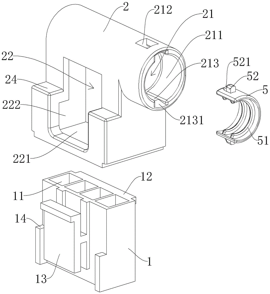
Fig. 1 is an exploded view of an embodiment of the terminal protection device of the present invention.
Fig. 2 is an installation diagram of an embodiment of the terminal protection device of the present invention.
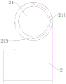
Fig. 3 is a right side view of a sheath in an embodiment of the terminal protection device of the present invention.
Fig. 4 is a schematic structural view of a half-surrounded tube clamped on a corrugated tube in an embodiment of the terminal protection device of the present invention.
Fig. 5 is a fragmentary view of the sheath with the needle mount installed in an embodiment of the terminal protection device of the present invention.
Fig. 6 is a schematic view of the mounting of the needle holder and the sheath in one embodiment of the terminal protection device of the present invention.
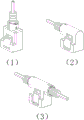
Fig. 7 is a schematic diagram of several different types of terminal protectors in accordance with the present invention.
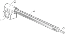
FIG. 8 is a schematic view of a threaded bellows assembly according to an embodiment of the present invention.
Fig. 9 is a flowchart of a threading method according to an embodiment of the present invention.
Fig. 10 is a threading schematic diagram of an embodiment of the threading method of the present invention.
In the drawings, each reference numeral means: the connector comprises a needle seat 1, a jack 11, a clamping strip 12, a side plate 13, a limiting table 14, a sheath 2, a corrugated pipe interface 21, a groove 211, a clamping hole 212, a guide groove 213, a guide slope 2131, a needle seat accommodating cavity 22, an opening 221, a side opening 222, a clamping interface 23, a guide slope 231, a step part 24, a circuit 3, a wiring terminal 31, a corrugated pipe 4, an outer annular groove 41, a semi-surrounding pipe clamp 5, an arc rib 51, a clamping protrusion 52 and a gentle slope 521.
Detailed Description
The following examples are intended to illustrate the present invention in detail and should not be construed as limiting the scope of the present invention in any way.
In the description of the present invention, it is to be understood that the terms "upper", "lower", "front", "rear", "left", "right", "top", "bottom", "inner", "outer", and the like, indicate orientations or positional relationships based on the orientations or positional relationships shown in the drawings, are merely for convenience in describing the present invention and simplifying the description, and do not indicate or imply that the device or element being referred to must have a particular orientation, be constructed and operated in a particular orientation, and thus, should not be construed as limiting the present invention.
Example 1:
a terminal protection device, please refer to fig. 1 to 7.
As shown in fig. 1, the terminal protection device provided by the embodiment of the present invention includes a pin base 1 for inserting a terminal, the pin base 1 is mainly used for installing the terminal, and the terminal is various conductive terminals such as a pin and a wire nose used in a wiring circuit, so that the terminal is fixed in the pin base 1 and arranged according to a certain rule. During actual wiring, the needle base 1 is inserted with another corresponding needle base, so that the wiring terminals in the two needle bases are correspondingly connected to realize power connection.
In the embodiment, the hub 1 is provided with four insertion holes 11 for inserting the connection terminals, one connection terminal is inserted into each insertion hole 11, the connection terminals in the four insertion holes 11 are arranged in a row, in other embodiments, the hub may have a shape, a structure and a size different from those of the hub in the embodiment, and the connection terminals in the hub may be arranged in other shapes.
The wiring terminal protection device also comprises a sheath 2, the sheath 2 is provided with a corrugated pipe interface 21 and a needle seat accommodating cavity 22 corresponding to the needle seat 1, the bottom of the needle seat accommodating cavity 22 is provided with an opening 221 for installing the needle seat 1, the needle seat 1 can be installed into the needle seat accommodating cavity 22 from the opening 221, the corrugated pipe interface 21 is communicated with the needle seat accommodating cavity 22, and the corrugated pipe interface 21 is used for connecting the end part of a corrugated pipe.
The bellows interface 21 in this embodiment is cylindrical in exterior, and the shape of the hub accommodating cavity 22 matches the shape of the hub 1, but in other embodiments, the outer shape of the bellows interface may be other shapes such as square, as long as the inner hole of the bellows interface is the shape corresponding to the bellows, and the shape of the hub accommodating cavity in other embodiments also matches the shape of the corresponding hub.
In use, as shown in fig. 2, a connection terminal is connected to the end of the line 3 for power connection, the line 3 is inserted into the bellows 4 (the line 3 and the bellows 4 in fig. 2 only have schematic effects, and do not represent actual length), the connection terminal connected to the front end of the line 3 extends out of the bellows 4, the connection terminal penetrates through the bellows interface 21 and can be mounted on the needle holder 1 after penetrating out of the opening 221, the needle holder 1 is then mounted in the needle holder accommodating cavity 22, and the front end of the bellows 4 is mounted in the bellows interface 21, so that the part of the line 3 located at the connection position of the bellows 4 and the needle holder 1 is not exposed, and the whole line 3 and the connection terminal are protected.
As shown in fig. 1, a semi-surrounding pipe clamp 5 is provided at the bellows joint 21, an inner wall surface of the semi-surrounding pipe clamp 5 is provided with arc ribs 51 corresponding to the outer annular groove 41 of the bellows 4 connected to the bellows joint 21, two arc ribs 51 are provided in the present embodiment, the distance between the two arc ribs 51 is the same as the distance between the outer annular grooves 41, and in other embodiments, a single arc rib or more than two arc ribs may be provided.
Accordingly, as shown in fig. 3, a groove 211 extending inward from the end surface and matching with the semi-surrounding pipe clamp 5 is provided in the bellows joint 21, the semi-surrounding pipe clamp 5 in this embodiment is arc-shaped as a whole, and the groove 211 is also arc-shaped, so that when the semi-surrounding pipe clamp 5 is installed in the groove 211, the bellows joint 21 is in a circular hole shape corresponding to the end of the connected bellows 4, thereby properly accommodating the end of the lower bellows 4.
As shown in fig. 4, when the corrugated pipe 4 needs to be connected to the corrugated pipe interface 21, the half-surrounded pipe clamp 5 is sleeved on the outer wall surface of the corrugated pipe 4, the arc-shaped ribs 51 on the inner wall surface of the half-surrounded pipe clamp 5 are correspondingly clamped in the outer annular grooves 41 on the outer wall surface of the corrugated pipe 4, then the end of the corrugated pipe 4 is inserted into the corrugated pipe interface 21 together with the half-surrounded pipe clamp 5, and the half-surrounded pipe clamp 5 can be tightly installed in the groove 211, so that the end of the corrugated pipe 4 can be tightly connected to the corrugated pipe interface 21.
In this embodiment, be equipped with the joint arch 52 on half 5 outer wall faces of surrounding pipe strap, it is equipped with joint hole 212 to correspond on the wall of recess 211, joint arch 52 has two, be located half 5 upper and lower both sides of surrounding pipe strap respectively, joint hole 212 corresponds there are two, be located the upper and lower both ends of recess 211 respectively, fall into corresponding joint hole 212 simultaneously when two joint arch 52, half 5 installing in recess 211 that can fasten of surrounding pipe strap, and the end card of bellows 4 is in half 5 of surrounding pipe strap, therefore, bellows 4 can not break away from sheath 2.
Furthermore, a guide groove 213 for guiding the clamping protrusion 52 to the clamping hole 212 is formed in the inner wall surface of the groove 211, a guide slope 2131 is formed at the outermost end of the guide groove 213, a gentle slope 521 is formed on one side, facing the corrugated pipe interface 21, of the clamping protrusion 52, when the semi-enclosed pipe clamp 5 is pushed into the groove 211 along the end of the groove 211, the clamping protrusion 52 can just reach the clamping hole 212 along the guide groove 213, and meanwhile, the gentle slope 521 and the guide slope 2131 are favorable for the clamping protrusion 52 to smoothly enter the guide groove 213.
The sheath 2 and the semi-surrounding pipe clamp 5 in the embodiment are both made of nylon, and can adapt to the environment from 110 ℃ to minus 60 ℃, so that the damage and deformation are avoided in severe environment.
Further, as shown in fig. 5 and fig. 6, in this embodiment, the outer wall surface of the needle base 1 is provided with the clamping strip 12, the needle base is correspondingly provided with the clamping interface 23 on the wall surface of the accommodating cavity 22, the lower edge of the inner side of the clamping interface 23 is provided with the guiding slope 231, when the needle base 1 is pushed in along the opening 221 of the bottom of the accommodating cavity 22 of the needle base, the clamping strip 12 can be clamped into the clamping interface 23 along the guiding slope 231, so that the needle base 1 can be tightly installed in the accommodating cavity 22 of the needle base.
As shown in fig. 1, the side surface of the needle holder 1 is provided with the side plate 13, the side surface of the sheath 2 is correspondingly provided with the side opening 222, and the side plate 13 is exposed from the side opening 222, so that the needle holder 1 can be conveniently moved out of the needle holder accommodating cavity 22 by pushing the side plate 13 at a later stage. Still be equipped with spacing platform 14 in the left side of needle file 1, the left side correspondence of sheath 2 is equipped with step portion 24, and spacing platform 14 card is in step portion 24, realizes the location of needle file 1 through joint strip 12 and spacing platform 14, prevents that needle file 1 from taking place to rock in needle file holds chamber 22.
Fig. 7 shows several terminal protection devices of different configurations in the present application, wherein this embodiment 1 is the terminal protection device shown in the (2) th sub-figure, and the corrugated tube interface of the terminal protection device is in L-shaped communication with the receiving cavity of the header, that is, the line penetrating through the corrugated tube is bent to connect with other corresponding headers. In other embodiments, the connection between the bellows connector and the needle seat accommodating cavity may be a straight connection in the drawing (1), i.e. the connection between the lines penetrating through the bellows and the needle seats is directly forward connected to the other corresponding needle seats; or the T-shaped communication mode in the drawing (3), when the corrugated pipe interfaces are in T-shaped communication with the needle seat accommodating cavity, two corrugated pipe interfaces are arranged and are respectively positioned at the left side and the right side of one end of the needle seat accommodating cavity, and the T-shaped communication mode enables lines penetrating through the corrugated pipes in two opposite directions to be gathered in the sheath for connecting other corresponding needle seats.
Example 2:
a bellows assembly, please refer to fig. 8.
The wiring terminal protection device provided by the embodiment of the invention comprises a corrugated pipe 4, the wiring terminal protection device in the embodiment 1 of the invention is arranged at the front end of the corrugated pipe 4, and the rear end of a circuit 3 can be connected with the power connection pins of other electrical components after extending out of the corrugated pipe 4. The circuit 3 is protected in bellows 4, and the part that lies in between bellows 4 and needle file 1 on the circuit 3 is protected in sheath 2, and the circuit 3 is very regular, is convenient for the arrangement of power consumption circuit in equipment such as various vehicles, various household electrical appliances, various machine tools, and the end of a thread can obtain good protection.
In other embodiments, the terminal protection devices in embodiment 1 may also be disposed at both ends of the corrugated tube, and the terminal protection devices at the front and rear ends of the corrugated tube are used to connect with corresponding needle seats respectively.
Example 3:
a threading method, please refer to fig. 9 and fig. 10.
As shown in fig. 9, the threading method provided by the embodiment of the present invention uses the bellows assembly of embodiment 2, and includes the following steps:
s100, the exposed end of each line in the corrugated pipe penetrates through the corrugated pipe interface of the sheath and penetrates out of the opening of the needle seat accommodating cavity.
Referring to fig. 10, before the step starts, the line 3 is inserted into the corrugated tube 4, so that the front end of the line 3 penetrates through the front port of the corrugated tube 4, the line 3 in this embodiment includes four electric wires, and the front end of each electric wire is connected to a connection terminal 31. This step is to insert the end of the line 3 exposed at the front end of the bellows 4 through the bellows joint 21 of the sheath 2 and out through the opening 221 of the hub accommodating chamber 22.
S200, correspondingly arranging the contact pins at the end parts of the lines in the needle base, then installing the needle base into the needle base accommodating cavity from the opening, and straightening the lines.
Referring to fig. 10, in this step, the four pins 31 at the front end of the line 3 are correspondingly disposed in the four insertion holes 11 of the hub 1, then the hub 1 is installed into the hub accommodating cavity 22 from the opening 221, and the line 3 is straightened and straightened, and when straightened and straightened, the line 3 is pulled backwards from the bellows joint 21, so as to prevent the front portion of the line 3 from being pushed into the sheath 2.
S300, correspondingly sleeving the semi-surrounding pipe clamp on one end, close to the sheath, of the outer wall surface of the corrugated pipe, and then inserting the semi-surrounding pipe clamp and the end of the corrugated pipe into a corrugated pipe interface to enable the end of the corrugated pipe to be connected with the sheath.
Referring to fig. 10, in this step, the half-surrounded pipe clamp 5 is sleeved on the outer wall surface of the front end of the corrugated pipe 4, and then the half-surrounded pipe clamp 5 and the front end of the corrugated pipe 4 are inserted into the corrugated pipe interface 21, when the half-surrounded pipe clamp 5 is inserted, the half-surrounded pipe clamp 5 is pushed inwards along the end of the groove 211, so that the front end of the corrugated pipe 4 is connected with the sheath 2, and since the half-surrounded pipe clamp 5 is clamped in the sheath 2 and the front end of the corrugated pipe 4 is clamped in the half-surrounded pipe clamp 5, the front end of the corrugated pipe 4 can be tightly connected in the sheath 2.
The threading method can lead the line 3 to be neatly arranged in the corrugated pipe 4 and the sheath 2, can prevent the line 3 from knotting in the sheath 2, and can prevent the local part of the line 3 from being damaged; meanwhile, by arranging the line in the corrugated tube 4 in a penetrating manner, a good protection effect is formed on the line 3 and the joint at the front end thereof by arranging the part of the line 3 between the corrugated tube 4 and the needle holder 1 and the whole needle holder 1 in the sheath 2.
While the present invention has been described in detail with reference to the drawings and the embodiments, those skilled in the art will understand that various specific parameters in the above embodiments can be changed without departing from the spirit of the present invention, and a plurality of specific embodiments are formed, which are common variation ranges of the present invention, and will not be described in detail herein.