CN111113974A - Safety supporting device of oil press - Google Patents

Safety supporting device of oil press Download PDF

Info

Publication number
CN111113974A
CN111113974A CN202010039193.7A CN202010039193A CN111113974A CN 111113974 A CN111113974 A CN 111113974A CN 202010039193 A CN202010039193 A CN 202010039193A CN 111113974 A CN111113974 A CN 111113974A
Authority
CN
China
Prior art keywords
connecting rod
sides
rod
box
threaded
Prior art date
Legal status (The legal status is an assumption and is not a legal conclusion. Google has not performed a legal analysis and makes no representation as to the accuracy of the status listed.)
Pending
Application number
CN202010039193.7A
Other languages
Chinese (zh)
Inventor
姜智勤
Current Assignee (The listed assignees may be inaccurate. Google has not performed a legal analysis and makes no representation or warranty as to the accuracy of the list.)
Xin Jieshun Hardware & Electromechanical Co ltd
Original Assignee
Xin Jieshun Hardware & Electromechanical Co ltd
Priority date (The priority date is an assumption and is not a legal conclusion. Google has not performed a legal analysis and makes no representation as to the accuracy of the date listed.)
Filing date
Publication date
Application filed by Xin Jieshun Hardware & Electromechanical Co ltd filed Critical Xin Jieshun Hardware & Electromechanical Co ltd
Priority to CN202010039193.7A priority Critical patent/CN111113974A/en
Publication of CN111113974A publication Critical patent/CN111113974A/en
Pending legal-status Critical Current

Links

Images

Classifications

    • B—PERFORMING OPERATIONS; TRANSPORTING
    • B30—PRESSES
    • B30B—PRESSES IN GENERAL
    • B30B1/00—Presses, using a press ram, characterised by the features of the drive therefor, pressure being transmitted directly, or through simple thrust or tension members only, to the press ram or platen
    • B30B1/32—Presses, using a press ram, characterised by the features of the drive therefor, pressure being transmitted directly, or through simple thrust or tension members only, to the press ram or platen by plungers under fluid pressure
    • B—PERFORMING OPERATIONS; TRANSPORTING
    • B30—PRESSES
    • B30B—PRESSES IN GENERAL
    • B30B15/00—Details of, or accessories for, presses; Auxiliary measures in connection with pressing
    • B—PERFORMING OPERATIONS; TRANSPORTING
    • B30—PRESSES
    • B30B—PRESSES IN GENERAL
    • B30B15/00—Details of, or accessories for, presses; Auxiliary measures in connection with pressing
    • B30B15/0076—Noise or vibration isolation means
    • B—PERFORMING OPERATIONS; TRANSPORTING
    • B30—PRESSES
    • B30B—PRESSES IN GENERAL
    • B30B15/00—Details of, or accessories for, presses; Auxiliary measures in connection with pressing
    • B30B15/28—Arrangements for preventing distortion of, or damage to, presses or parts thereof
    • F—MECHANICAL ENGINEERING; LIGHTING; HEATING; WEAPONS; BLASTING
    • F16—ENGINEERING ELEMENTS AND UNITS; GENERAL MEASURES FOR PRODUCING AND MAINTAINING EFFECTIVE FUNCTIONING OF MACHINES OR INSTALLATIONS; THERMAL INSULATION IN GENERAL
    • F16F—SPRINGS; SHOCK-ABSORBERS; MEANS FOR DAMPING VIBRATION
    • F16F15/00—Suppression of vibrations in systems; Means or arrangements for avoiding or reducing out-of-balance forces, e.g. due to motion
    • F16F15/02—Suppression of vibrations of non-rotating, e.g. reciprocating systems; Suppression of vibrations of rotating systems by use of members not moving with the rotating systems
    • F16F15/04—Suppression of vibrations of non-rotating, e.g. reciprocating systems; Suppression of vibrations of rotating systems by use of members not moving with the rotating systems using elastic means
    • F16F15/06—Suppression of vibrations of non-rotating, e.g. reciprocating systems; Suppression of vibrations of rotating systems by use of members not moving with the rotating systems using elastic means with metal springs
    • F16F15/067—Suppression of vibrations of non-rotating, e.g. reciprocating systems; Suppression of vibrations of rotating systems by use of members not moving with the rotating systems using elastic means with metal springs using only wound springs

Landscapes

  • Engineering & Computer Science (AREA)
  • Mechanical Engineering (AREA)
  • Physics & Mathematics (AREA)
  • General Engineering & Computer Science (AREA)
  • Acoustics & Sound (AREA)
  • Aviation & Aerospace Engineering (AREA)
  • Fluid Mechanics (AREA)
  • Presses And Accessory Devices Thereof (AREA)

Abstract

本发明公开了一种油压机的安全支撑装置,包括底板、调节箱和第一导杆,所述调节箱一侧的两端皆均匀设置有固定块,且固定块的顶端均设置有螺纹支架,所述调节箱底端的两侧均匀设置有固定支架,且固定支架的底端均延伸至底板的内部,所述放置箱的两侧内壁之间安装有缓冲板,且缓冲板两侧的底端均延伸至限位槽的内部。本发明通过在调节箱的一侧中间位置处安装有摇把,且摇把一侧调节箱的两侧内壁之间安装有螺纹杆,调节箱内部螺纹杆外壁的两侧均安装有螺纹滑块,且螺纹滑块的顶端均安装有第一导杆,该结构可以将油压机进行紧固夹持,有利于保证油压机的正常工作。

Figure 202010039193

The invention discloses a safety support device for a hydraulic press, comprising a bottom plate, an adjustment box and a first guide rod. Both ends of one side of the adjustment box are evenly provided with fixed blocks, and the top of the fixed blocks are provided with threaded brackets. Both sides of the bottom end of the adjustment box are evenly provided with fixed brackets, and the bottom ends of the fixed brackets extend to the interior of the bottom plate, and a buffer plate is installed between the inner walls of the two sides of the placing box, and the bottom ends on both sides of the buffer plate are extends to the inside of the limit slot. In the present invention, a crank handle is installed at the middle position of one side of the adjustment box, and a threaded rod is installed between the two inner walls of the adjustment box on one side of the crank handle, and threaded sliders are installed on both sides of the outer wall of the threaded rod inside the adjustment box. , and a first guide rod is installed on the top of the threaded slide block, and this structure can fasten and clamp the hydraulic press, which is beneficial to ensure the normal operation of the hydraulic press.

Figure 202010039193

Description

Safety supporting device of oil press
Technical Field
The invention relates to the technical field of supporting equipment, in particular to a safe supporting device of an oil press.
Background
The oil press is a machine which uses a one-way valve to make hydraulic oil circulate in an oil tank to make an oil cylinder/piston circularly do work so as to complete a certain mechanical action as productivity, and is a hydraulic press. The hydraulic press uses special hydraulic oil as working medium, uses hydraulic pump as power source, uses the pump force to make the hydraulic oil enter into the cylinder/piston through hydraulic pipeline, then there are several groups of mutually matched sealing elements in the cylinder/piston, the sealing of different positions are different, but all play the role of sealing, make the hydraulic oil can not reveal, and the existing supporting device has many disadvantages.
First, traditional strutting arrangement does not have the function of height control, and the hydraulic press is when using, according to the height that needs adjustment hydraulic press.
Secondly, the conventional supporting device does not have a damping function, and when the oil press is used, the force of the oil pressure is large, and if the damping function is not provided, the device is easily damaged.
Third, the conventional supporting device does not have a good fixing structure, and when supporting the oil press, it is necessary to ensure that the oil press is tightly mounted on the device, otherwise the oil press is easily separated from the device during operation, resulting in damage.
Disclosure of Invention
The present invention is directed to a safety supporting device for a hydraulic press, which solves the problems of the prior art that the hydraulic press does not have a height adjusting function and the height of the hydraulic press needs to be adjusted according to different requirements when the hydraulic press is used.
In order to achieve the purpose, the invention provides the following technical scheme: a safety supporting device of an oil press comprises a bottom plate, an adjusting box and a first guide rod, wherein both ends of one side of the adjusting box are uniformly provided with fixed blocks, the top ends of the fixed blocks are provided with threaded brackets, the two sides of the bottom end of the adjusting box are uniformly provided with fixed brackets, the bottom ends of the fixed brackets extend into the bottom plate, the top ends of the first guide rods extend to the upper part of the adjusting box, one side of each first guide rod is provided with a second guide rod, the other side of the second guide rod extends to the other side of the first guide rod, the other side of the second guide rod is provided with a clamping block, the middle position of the top end of the adjusting box is provided with a placing box, and the inner parts of the two sides of the placing box are respectively provided with a limiting groove, a buffer plate is arranged between the inner walls of the two sides of the placing box, and the bottom of buffer board both sides all extends to the inside of spacing groove, place the both sides of incasement portion bottom and all install the second spring.
Preferably, the top of threaded support all welds the rotary disk, and the bottom of threaded support all extends to the below of fixed block.
Preferably, the intermediate position department of regulating box bottom evenly installs the third connecting rod through the articulated elements, and the bottom of third connecting rod all installs solid fixed sliding block through the articulated elements, the motor is installed to one side of solid fixed sliding block, and the inside of motor one side solid fixed sliding block is provided with the lead screw, one side of lead screw extends to solid fixed sliding block's opposite side, and solid fixed sliding block's bottom all is provided with the second connecting rod through the articulated elements to the bottom of second connecting rod is passed through the articulated elements and is installed the bottom plate.
Preferably, the crank is installed to one side intermediate position department of regulating box, and installs the threaded rod between the both sides inner wall of crank one side regulating box, the screw slider is all installed to the both sides of the inside threaded rod outer wall of regulating box, and the top of screw slider all installs first guide arm.
Preferably, the bottom of the second guide rod on one side of the first guide rod is provided with a first connection rod, first springs are uniformly arranged between one sides of the first guide rods on one side of the first connection rod, and the inside of the top end of the adjusting box at the bottom end of the first connection rod is provided with a movable sliding block.
Preferably, place incasement portion's bottom intermediate position department and install the fifth connecting rod, and the outer wall intermediate position department of fifth connecting rod installs the third spring, the fourth connecting rod is all installed through the articulated elements in the top of third spring both sides fifth connecting rod, and the top of fourth connecting rod all passes through articulated elements fixed connection in the bottom of buffer board.
Compared with the prior art, the invention has the beneficial effects that:
(1) the oil press is placed in the placing box through the placing box, the crank is shaken, the threaded rod rotates to be matched with the internal thread of the threaded slider, the threaded slider can move to drive the first guide rod and the second guide rod to move simultaneously, the oil press is clamped, the second guide rod moves and is matched with the moving slider simultaneously, the first connection rod can move, when the oil press is clamped, the first guide rod extrudes the first spring to deform, the buffering can be reduced, the damage to the oil press is prevented, and the oil press can be clamped conveniently by the structure;
(2) the motor can be opened to work as required by installing the motor, the screw rod, the bottom plate, the fixed sliding block, the second connecting rod and the third connecting rod, the screw rod rotates and is matched with the internal thread of the fixed sliding block, so that the second connecting rod and the third connecting rod can be displaced on the screw rod, the device can be supported by the bottom plate to adjust the height of the device, then the threaded support rotates when the rotating disk rotates and is matched with the internal thread of the fixed block, so that the threaded support is supported on the ground, the device is assisted to be fixed, and the structure is convenient for adjusting the height of the device;
(3) through installing buffer board, spacing groove, second spring, fourth connecting rod and fifth connecting rod, the hydraulic press during operation can produce pressure, and pressure passes to the buffer board, and buffer board cooperation spacing groove takes place to remove, when the deformation takes place for the extrusion second spring, and the third spring that the fourth connecting rod can extrude on the fifth connecting rod takes place to deform, slows down pressure, reaches absorbing effect, and this structure is favorable to increaseing the shock attenuation effect of device.
Drawings
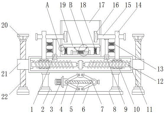
FIG. 1 is a schematic cross-sectional view of the apparatus of the present invention;
FIG. 2 is a schematic top view of the apparatus of the present invention;
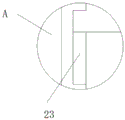
FIG. 3 is an enlarged schematic view of the apparatus of the present invention at position A;
FIG. 4 is an enlarged view of the apparatus B of the present invention;
in the figure: 1. a first link; 2. fixing a bracket; 3. a motor; 4. fixing the sliding block; 5. a screw rod; 6. a second link; 7. a third link; 8. a base plate; 9. moving the slide block; 10. a threaded slider; 11. an adjusting box; 12. a threaded rod; 13. a first spring; 14. a first guide bar; 15. a second guide bar; 16. a clamping block; 17. placing a box; 18. a second spring; 19. a buffer plate; 20. rotating the disc; 21. a fixed block; 22. a threaded support; 23. a limiting groove; 24. a fourth link; 25. a fifth link; 26. a third spring; 27. a crank handle.
Detailed Description
The technical solutions in the embodiments of the present invention will be clearly and completely described below with reference to the drawings in the embodiments of the present invention, and it is obvious that the described embodiments are only a part of the embodiments of the present invention, and not all of the embodiments. All other embodiments, which can be derived by a person skilled in the art from the embodiments given herein without making any creative effort, shall fall within the protection scope of the present invention.
Referring to fig. 1-4, an embodiment of the present invention is shown: a safety supporting device of an oil press comprises a bottom plate 8, an adjusting box 11 and a first guide rod 14, wherein both ends of one side of the adjusting box 11 are uniformly provided with fixing blocks 21, and the top ends of the fixing blocks 21 are provided with threaded brackets 22;
the rotating discs 20 are welded at the top ends of the threaded supports 22, and the bottom ends of the threaded supports 22 extend to the lower portions of the fixed blocks 21;
the rotating disc 20 is rotated, the threaded support 22 rotates to match the internal thread of the fixed block 21, and the threaded support 22 is supported on the ground;
the middle position of the bottom end of the adjusting box 11 is uniformly provided with third connecting rods 7 through hinges, the bottom ends of the third connecting rods 7 are respectively provided with a fixed sliding block 4 through the hinges, one side of each fixed sliding block 4 is provided with a motor 3, the type of the motor 3 can be Y160M1-2, a lead screw 5 is arranged inside the fixed sliding block 4 on one side of the motor 3, one side of the lead screw 5 extends to the other side of the fixed sliding block 4, the bottom ends of the fixed sliding blocks 4 are respectively provided with a second connecting rod 6 through the hinges, and the bottom end of the second connecting rod 6 is provided with a bottom plate 8 through the hinges;
the motor 3 is started to work, the screw rod 5 rotates, and the second connecting rod 6 and the third connecting rod 7 can be enabled to move on the screw rod 5 by matching with the internal thread of the fixed sliding block 4, so that the device can be supported by the bottom plate 8 to adjust the height of the device;
the two sides of the bottom end of the adjusting box 11 are uniformly provided with the fixed supports 2, and the bottom ends of the fixed supports 2 extend into the bottom plate 8;
a crank 27 is arranged in the middle of one side of the adjusting box 11, a threaded rod 12 is arranged between the inner walls of the two sides of the adjusting box 11 on one side of the crank 27, threaded sliders 10 are arranged on two sides of the outer wall of the threaded rod 12 in the adjusting box 11, and first guide rods 14 are arranged at the top ends of the threaded sliders 10;
the crank 27 is shaken, the threaded rod 12 rotates, the threaded slider 10 can move by matching with the internal thread of the threaded slider 10, and the first guide rod 14 and the second guide rod 15 are driven to move simultaneously, so that the oil press is clamped by the clamping block 16;
the top ends of the first guide rods 14 extend to the upper part of the adjusting box 11, one sides of the first guide rods 14 are provided with second guide rods 15, the other sides of the second guide rods 15 extend to the other sides of the first guide rods 14, and the other sides of the second guide rods 15 are provided with clamping blocks 16;
the bottom ends of the second guide rods 15 on one side of the first guide rod 14 are respectively provided with a first connecting rod 1, first springs 13 are uniformly arranged between the first guide rods 14 on one side of the first connecting rod 1, and the inside of the top end of the regulating box 11 at the bottom end of the first connecting rod 1 is respectively provided with a movable sliding block 9;
the second guide rod 15 moves and is matched with the moving slide block 9, so that the first connecting rod 1 can move, when the oil press is clamped, the first guide rod 14 extrudes the first spring 13 to deform, the buffering is less, and the damage to the oil press is prevented;
a placing box 17 is installed in the middle of the top end of the adjusting box 11, limiting grooves 23 are formed in the inner portions of two sides of the placing box 17, a buffer plate 19 is installed between the inner walls of two sides of the placing box 17, the bottom ends of two sides of the buffer plate 19 extend into the limiting grooves 23, and second springs 18 are installed on two sides of the bottom end of the inner portion of the placing box 17;
a fifth connecting rod 25 is arranged in the middle of the bottom end in the placing box 17, a third spring 26 is arranged in the middle of the outer wall of the fifth connecting rod 25, fourth connecting rods 24 are arranged at the top ends of the fifth connecting rods 25 on the two sides of the third spring 26 through hinge parts, and the top ends of the fourth connecting rods 24 are fixedly connected to the bottom end of the buffer plate 19 through the hinge parts;
when the oil press is started to work, pressure is generated during work and is transmitted to the buffer plate 19, the buffer plate 19 is matched with the limiting groove 23 to move, the second spring 18 is extruded to deform, and meanwhile, the fourth connecting rod 24 can extrude the third spring 26 on the fifth connecting rod 25 to deform, so that the pressure is reduced, and the damping effect is achieved.
The working principle is as follows: when the hydraulic press is used, the hydraulic press is placed in the placing box 17, then the crank 27 is shaken, the threaded rod 12 rotates to be matched with the internal thread of the threaded slider 10, the threaded slider 10 can move to drive the first guide rod 14 and the second guide rod 15 to move simultaneously, so that the oil press is clamped by the clamping block 16, the first connecting rod 1 can move by being matched with the moving slider 9 while the second guide rod 15 moves, when the oil press is clamped, the first guide rod 14 extrudes the first spring 13 to deform, less buffering can be realized, the damage to the oil press is prevented, the height of the oil press is adjusted according to needs, the motor 3 is started to work, the screw rod 5 rotates to be matched with the internal thread of the fixed slider 4, the second connecting rod 6 and the third connecting rod 7 can displace on the screw rod 5, so that the device can be supported by the bottom plate 8 to adjust the height of the device, then the rotating disc 20 is rotated, and the threaded bracket 22 rotates, the internal thread of cooperation fixed block 21 for screw thread support 22 supports on ground, and supplementary fixing device, the regulation finishes, opens the hydraulic press during operation, and the during operation can produce pressure, and pressure passes to buffer board 19, and buffer board 19 cooperation spacing groove 23 takes place to remove, and when extrusion second spring 18 took place deformation, fourth connecting rod 24 can extrude the third spring 26 on the fifth connecting rod 25 and take place deformation, slows down pressure, reaches absorbing effect.
It will be evident to those skilled in the art that the invention is not limited to the details of the foregoing illustrative embodiments, and that the present invention may be embodied in other specific forms without departing from the spirit or essential attributes thereof. The present embodiments are therefore to be considered in all respects as illustrative and not restrictive, the scope of the invention being indicated by the appended claims rather than by the foregoing description, and all changes which come within the meaning and range of equivalency of the claims are therefore intended to be embraced therein. Any reference sign in a claim should not be construed as limiting the claim concerned.

Claims (6)

1. The utility model provides a safe strutting arrangement of hydraulic press, includes bottom plate (8), regulating box (11) and first guide arm (14), its characterized in that: the two ends of one side of the adjusting box (11) are uniformly provided with fixing blocks (21), the top ends of the fixing blocks (21) are respectively provided with a threaded support (22), the two sides of the bottom end of the adjusting box (11) are respectively provided with a fixing support (2), the bottom end of each fixing support (2) extends into the bottom plate (8), the top end of each first guide rod (14) extends to the upper side of the adjusting box (11), one side of each first guide rod (14) is provided with a second guide rod (15), the other side of each second guide rod (15) extends to the other side of each first guide rod (14), the other side of each second guide rod (15) is provided with a clamping block (16), the middle position of the top end of the adjusting box (11) is provided with a placing box (17), the inner parts of the two sides of the placing box (17) are respectively provided with a limiting groove (23), and a buffer plate (19) is arranged between the inner walls of the two sides of the placing box, and the bottom of buffer board (19) both sides all extends to the inside of spacing groove (23), place the both sides of the inside bottom of case (17) and all install second spring (18).
2. The safety support device for oil press as claimed in claim 1, wherein: the top of screw thread support (22) all welds rotary disk (20), and the bottom of screw thread support (22) all extends to the below of fixed block (21).
3. The safety support device for oil press as claimed in claim 1, wherein: the utility model discloses a motor, including regulating box (11), motor (3) and the inside of motor (3) one side fixed sliding block (4) is provided with lead screw (5), one side of lead screw (5) extends to the opposite side of fixed sliding block (4), and the bottom of fixed sliding block (4) all is provided with second connecting rod (6) through the articulated elements to bottom through the articulated elements of second connecting rod (6) installs bottom plate (8) in the intermediate position department of regulating box (11) bottom.
4. The safety support device for oil press as claimed in claim 1, wherein: crank (27) are installed to one side intermediate position department of regulating box (11), and install threaded rod (12) between the both sides inner wall of crank (27) one side regulating box (11), threaded slider (10) are all installed to the both sides of regulating box (11) inside threaded rod (12) outer wall, and first guide arm (14) are all installed on the top of threaded slider (10).
5. The safety support device for oil press as claimed in claim 1, wherein: first connecting rod (1) is all installed to the bottom of first guide arm (14) one side second guide arm (15), and all evenly installs first spring (13) between one side of first connecting rod (1) one side first guide arm (14) to the inside on first connecting rod (1) bottom regulating box (11) top all installs and removes slider (9).
6. The safety support device for oil press as claimed in claim 1, wherein: place the bottom intermediate position department of case (17) inside and install fifth connecting rod (25), and the outer wall intermediate position department of fifth connecting rod (25) installs third spring (26), fourth connecting rod (24) are all installed through the articulated elements to the top of third spring (26) both sides fifth connecting rod (25), and the top of fourth connecting rod (24) all passes through articulated elements fixed connection in the bottom of buffer board (19).
CN202010039193.7A 2020-01-14 2020-01-14 Safety supporting device of oil press Pending CN111113974A (en)

Priority Applications (1)

Application Number Priority Date Filing Date Title
CN202010039193.7A CN111113974A (en) 2020-01-14 2020-01-14 Safety supporting device of oil press

Applications Claiming Priority (1)

Application Number Priority Date Filing Date Title
CN202010039193.7A CN111113974A (en) 2020-01-14 2020-01-14 Safety supporting device of oil press

Publications (1)

Publication Number Publication Date
CN111113974A true CN111113974A (en) 2020-05-08

Family

ID=70490504

Family Applications (1)

Application Number Title Priority Date Filing Date
CN202010039193.7A Pending CN111113974A (en) 2020-01-14 2020-01-14 Safety supporting device of oil press

Country Status (1)

Country Link
CN (1) CN111113974A (en)

Cited By (2)

* Cited by examiner, † Cited by third party
Publication number Priority date Publication date Assignee Title
CN111706571A (en) * 2020-06-27 2020-09-25 孙钟 Oil cylinder piston with high strength and good sealing performance for trailer pump air extraction unit
CN112879748A (en) * 2020-10-21 2021-06-01 潘倩倩 An anti-shake human kinect catcher

Citations (10)

* Cited by examiner, † Cited by third party
Publication number Priority date Publication date Assignee Title
KR20130120294A (en) * 2012-04-25 2013-11-04 삼성중공업 주식회사 Supporting apparatus and moving carrier moving the same
CN204981004U (en) * 2015-07-31 2016-01-20 上海鼎凡电工机械股份有限公司 Push away ascending device of material
CN207124545U (en) * 2017-06-23 2018-03-20 国网河南省电力公司郑州供电公司 A kind of voltage plastic package motor rotor enters axle and moves back axle dual-purpose apparatus
CN207416672U (en) * 2017-11-24 2018-05-29 安徽智锐汽车有限公司 A kind of automobile-used compressor mounting bracket of refrigeration
CN207416074U (en) * 2017-08-16 2018-05-29 苏州胜铭龙油压设备有限公司 One kind is new to be easily installed oil pressure machine support
CN208057360U (en) * 2018-03-31 2018-11-06 胡乐顺 A kind of operation of air conditioning systems compression mechanism
CN208052671U (en) * 2018-03-28 2018-11-06 泉州山水源泉机械科技有限公司 A kind of safety supporting device of hydraulic press
CN109317873A (en) * 2018-12-01 2019-02-12 郑州日产汽车有限公司 Welding robot for picking-up vehicle side bottom beam
CN209083500U (en) * 2018-11-29 2019-07-09 天津富瑞滋制冷科技有限公司 A kind of refrigeration compressor with shock-absorbing function
CN211683618U (en) * 2020-01-14 2020-10-16 苏州鑫捷顺五金机电有限公司 Safety supporting device of oil press

Patent Citations (10)

* Cited by examiner, † Cited by third party
Publication number Priority date Publication date Assignee Title
KR20130120294A (en) * 2012-04-25 2013-11-04 삼성중공업 주식회사 Supporting apparatus and moving carrier moving the same
CN204981004U (en) * 2015-07-31 2016-01-20 上海鼎凡电工机械股份有限公司 Push away ascending device of material
CN207124545U (en) * 2017-06-23 2018-03-20 国网河南省电力公司郑州供电公司 A kind of voltage plastic package motor rotor enters axle and moves back axle dual-purpose apparatus
CN207416074U (en) * 2017-08-16 2018-05-29 苏州胜铭龙油压设备有限公司 One kind is new to be easily installed oil pressure machine support
CN207416672U (en) * 2017-11-24 2018-05-29 安徽智锐汽车有限公司 A kind of automobile-used compressor mounting bracket of refrigeration
CN208052671U (en) * 2018-03-28 2018-11-06 泉州山水源泉机械科技有限公司 A kind of safety supporting device of hydraulic press
CN208057360U (en) * 2018-03-31 2018-11-06 胡乐顺 A kind of operation of air conditioning systems compression mechanism
CN209083500U (en) * 2018-11-29 2019-07-09 天津富瑞滋制冷科技有限公司 A kind of refrigeration compressor with shock-absorbing function
CN109317873A (en) * 2018-12-01 2019-02-12 郑州日产汽车有限公司 Welding robot for picking-up vehicle side bottom beam
CN211683618U (en) * 2020-01-14 2020-10-16 苏州鑫捷顺五金机电有限公司 Safety supporting device of oil press

Cited By (2)

* Cited by examiner, † Cited by third party
Publication number Priority date Publication date Assignee Title
CN111706571A (en) * 2020-06-27 2020-09-25 孙钟 Oil cylinder piston with high strength and good sealing performance for trailer pump air extraction unit
CN112879748A (en) * 2020-10-21 2021-06-01 潘倩倩 An anti-shake human kinect catcher

Similar Documents

Publication Publication Date Title
CN211683618U (en) Safety supporting device of oil press
CN220625970U (en) Bending test machine for equalizing ring production detection
CN207656192U (en) A kind of clamping device for automotive automation production line
CN211649568U (en) A gas cabinet installation structure for upgrading old equipment
CN108637628B (en) Piston ring and device for piston assembly
CN105666081A (en) Anti-twisting assembly tool of vehicle front lower swing arm back hydraulic bushing
CN218964724U (en) Clamp for processing end cover connecting hole on window surface of half axle shell
CN218946428U (en) A metal pipe drilling support device
CN217700937U (en) Hydraulic punching machine with shockproof structure
CN213337937U (en) Novel energy-conserving motor laboratory bench that protection nature is high
CN211450224U (en) Projection equipment convenient to installation for multimedia interaction
CN106914832B (en) A kind of quick support compression mechanism of automobile product part
CN211714990U (en) Door and window wool top grabbing mechanism and automatic wool top penetrating machine
CN219426157U (en) metal cutting device
CN210587267U (en) Drilling device for machining electromagnetic clutch hub of automobile air conditioner
CN208801000U (en) A kind of oxygen supply valve mounting arrangement
CN216208081U (en) Fatigue tension and compression test device under high and low temperature environment
CN206316627U (en) The plug transposer of magnetic valve core assembly assembly machine
CN221569986U (en) Hydraulic cylinder reinforcing bracket
CN210549126U (en) Distortion device is prevented in welding of air conditioner radiator core
CN219881745U (en) Hydraulic adjusting device for cantilever control box
CN221549985U (en) End automatic clamping device for oil pressure shock absorber test robot
CN222652560U (en) Automatic gap adjusting arm static torsion experimental machine
CN224178413U (en) Actuator convenient to installation
CN220234094U (en) Adjustable aluminum alloy cable bridge

Legal Events

Date Code Title Description
PB01 Publication
PB01 Publication
SE01 Entry into force of request for substantive examination
CB02 Change of applicant information

Address after: 215000 No.78, Tinghe Road, Suzhou Industrial Park, Jiangsu Province

Applicant after: Suzhou xinjieshun Precision Technology Co.,Ltd.

Address before: No.78 Tinghe Road, Suzhou Industrial Park, Suzhou, Jiangsu Province, 215000

Applicant before: XIN JIESHUN HARDWARE & ELECTROMECHANICAL Co.,Ltd.

CB02 Change of applicant information
RJ01 Rejection of invention patent application after publication

Application publication date: 20200508

RJ01 Rejection of invention patent application after publication