CN111112478A - Replaceable automatic stamping die - Google Patents
Replaceable automatic stamping die Download PDFInfo
- Publication number
- CN111112478A CN111112478A CN202010080130.6A CN202010080130A CN111112478A CN 111112478 A CN111112478 A CN 111112478A CN 202010080130 A CN202010080130 A CN 202010080130A CN 111112478 A CN111112478 A CN 111112478A
- Authority
- CN
- China
- Prior art keywords
- cavity
- sliding
- movable
- fixedly connected
- end wall
- Prior art date
- Legal status (The legal status is an assumption and is not a legal conclusion. Google has not performed a legal analysis and makes no representation as to the accuracy of the status listed.)
- Withdrawn
Links
Images


Classifications
-
- B—PERFORMING OPERATIONS; TRANSPORTING
- B21—MECHANICAL METAL-WORKING WITHOUT ESSENTIALLY REMOVING MATERIAL; PUNCHING METAL
- B21D—WORKING OR PROCESSING OF SHEET METAL OR METAL TUBES, RODS OR PROFILES WITHOUT ESSENTIALLY REMOVING MATERIAL; PUNCHING METAL
- B21D37/00—Tools as parts of machines covered by this subclass
- B21D37/14—Particular arrangements for handling and holding in place complete dies
-
- B—PERFORMING OPERATIONS; TRANSPORTING
- B21—MECHANICAL METAL-WORKING WITHOUT ESSENTIALLY REMOVING MATERIAL; PUNCHING METAL
- B21D—WORKING OR PROCESSING OF SHEET METAL OR METAL TUBES, RODS OR PROFILES WITHOUT ESSENTIALLY REMOVING MATERIAL; PUNCHING METAL
- B21D37/00—Tools as parts of machines covered by this subclass
- B21D37/10—Die sets; Pillar guides
Abstract
The replaceable automatic stamping die comprises a box body, wherein a cavity with a leftward opening is formed in the box body, a first rotating shaft is rotatably connected to the lower end wall of the cavity, a circular rotating disc is slidably connected to the upper end of the first rotating shaft through a connecting device, 3 die grooves are uniformly distributed in the upper end wall of the circular rotating disc, a rectangular clamping groove is formed in the center of the circular rotating disc, second sliding grooves are symmetrically formed in the left side and the right side of the first rotating shaft on the lower end wall of the cavity, a jacking block is slidably matched in the second sliding grooves, a first spring fixedly connected with the jacking block is mounted on the bottom wall of the second sliding groove, a first movable cavity is formed in the lower end wall of the cavity, the lower end of the first rotating shaft extends into the first movable cavity to be rotatably connected with the lower end wall of the first movable cavity, and a transmission device is arranged in.
Description
Technical Field
The invention relates to the technical field of dies, in particular to a replaceable automatic stamping die.
Background
At present, various electrical appliances are in use, and the demand for circuit boards is increasing rapidly. A certain amount of circuit boards in electronic products are flexible circuit boards, and because the fixed positions of the flexible circuit boards cannot be seriously deformed, a reinforcing sheet needs to be installed to fix the flexible circuit boards, the reinforcing sheet is generally directly added in the production process, and most manufacturers at the present stage arrange a large amount of manual work to install the flexible circuit boards. On one hand, the manual efficiency is low, and the labor consumption is long when large-batch products are produced, so that the benefit is influenced; on the other hand, each person has his own mounting technique or habit, and the product is prone to deviation and poor in stability.
Disclosure of Invention
Aiming at the technical defects, the invention provides a replaceable automatic stamping die which can overcome the defects.
The invention relates to a replaceable automatic stamping die, which comprises a box body, wherein a cavity with a leftward opening is arranged in the box body, a first rotating shaft is rotatably connected to the lower end wall of the cavity, the upper end of the first rotating shaft is slidably connected with a circular rotating disc through a connecting device, three die grooves are uniformly distributed on the upper end wall of the circular rotating disc, a rectangular clamping groove is formed in the center of the circular rotating disc, second sliding grooves are symmetrically formed in the left side and the right side of the first rotating shaft on the lower end wall of the cavity, a jacking block is slidably matched in the second sliding grooves, a first spring fixedly connected with the jacking block is mounted on the bottom wall of the second sliding groove, a first movable cavity is arranged on the lower end wall of the cavity, the lower end of the first rotating shaft extends into the first movable cavity to be rotatably connected with the lower end wall of the first movable cavity, a transmission device is arranged in the first movable cavity, the upper end wall of the transmission cavity is fixedly connected with a third motor, the third motor is in power connection with a second screw, the lower end of the second screw is in rotating connection with the lower end wall of the transmission cavity, the second screw is in threaded connection with a second movable block in sliding fit with the transmission cavity, the second movable block is in rotating connection with a third rotating shaft, the third rotating shaft is in sliding fit with a wall body between the cavity and the transmission cavity and is fixedly connected with a rectangular fixture block in the cavity, the upper end of the transmission cavity is provided with a first sliding cavity, the upper end of the first sliding cavity is provided with a third movable cavity, the upper end wall of the third movable cavity is fixedly connected with a second motor, the second motor is in power connection with a first transmission shaft, the lower end of the first transmission shaft is in rotating connection with the wall body between the third movable cavity and the first sliding cavity and is fixedly connected with a half gear in the first sliding cavity, the first sliding cavity is internally provided with a clamping device, the first transmission shaft is fixedly connected with a first belt pulley in the third movable cavity, the first belt pulley is connected with a second belt pulley through a first transmission belt, the right end of the third movable cavity is connected with a fourth movable cavity, the second belt pulley is fixedly connected with a second transmission shaft in the fourth movable cavity, the second transmission shaft is rotatably connected with the upper end wall of the fourth movable cavity, the second transmission shaft is provided with a third trapezoidal block, the third trapezoidal block is slidably connected with a sixth helical gear, the left side of the sixth helical gear is meshed with a fifth helical gear, the fifth helical gear is fixedly connected with a crank rocker, the crank rocker is connected with a stamping device, the lower end of the sixth holding wheel is provided with a second T-shaped annular groove, the second T-shaped annular groove is slidably connected with a second connecting rod, and the lower end of the fourth movable cavity is provided with a fifth movable cavity, and an auxiliary connecting device is arranged in the fifth movable cavity.
Preferably, connecting device is including being located the spread groove of circular carousel diapire, spread groove sliding fit first pivot, spread groove left and right sides end wall symmetry is equipped with the second sliding tray, first pivot upper end is equipped with first sliding tray, the first electro-magnet of fixedly connected with in the first sliding tray, the left and right ends sliding fit of first spout has the slider that has the inclined plane, the slider passes through third spring coupling first electro-magnet.
Preferably, the transmission device comprises a worm rotatably connected in the left end wall of the first movable cavity, a hydraulic cavity is arranged at the lower side of the first movable cavity, a first piston plate is arranged at the upper end of the side of the hydraulic cavity, a first ejector rod is fixedly connected to the upper end of the first piston plate, the upper end of the first ejector rod penetrates through the upper end wall of the hydraulic cavity and extends into the first chute, a second piston plate is arranged at the upper end of the right side of the hydraulic cavity, a second ejector rod is fixedly connected to the upper end of the second piston plate, the upper end of the second ejector rod penetrates through the upper end wall of the hydraulic cavity and extends into the first movable cavity, a first trapezoidal block is fixedly connected to the first movable cavity through the first rotating shaft, a turbine is in sliding fit with the first trapezoidal block, the rear end of the turbine is engaged with the worm, a first T-shaped annular groove is arranged at the lower end of the turbine, and the lower end of the first T, the first movable cavity right-hand member is equipped with the second activity chamber, the worm right-hand member stretch into the second activity chamber and with first activity chamber with wall body rotation connection between the second activity chamber, the worm in the second rotates the intracavity fixedly connected with first helical gear, second transmission shaft lower extreme stretch into the second activity chamber and with the second activity chamber with wall body rotation connection between the fourth activity chamber, second transmission shaft lower extreme in the second activity intracavity fixedly connected with second trapezoidal piece, second trapezoidal piece sliding fit has the second helical gear, second helical gear upper end is equipped with third T shape annular.
Preferably, the clamping device comprises an annular rack in sliding fit with the first sliding cavity, the clamping device realizes a feeding function at the front end of the annular rack, the clamping device realizes a discharging function at the rear end of the annular rack, the inner side of the annular rack is meshed with the half gear, a second sliding cavity is arranged at the lower end of the first sliding cavity, a first chute is arranged at the lower end of the second sliding cavity, the front end and the rear end of the annular rack are symmetrically and fixedly connected with a first fixed block, the lower end wall of the first fixed block is rotatably connected with a first screw rod, the first screw rod extends into the second sliding cavity, a second fixed block is in sliding fit with the second sliding cavity, a first motor is fixedly connected with the upper end wall of the second fixed block, the first motor is in power connection with the first screw rod, a first movable block is in threaded fit with the first screw rod, and a first connecting rod is movably and fixedly connected with the first connecting rod, and the lower end of the first connecting rod is fixedly connected with a second electromagnet.
Preferably, a second rotating cavity is formed in the left side of the fourth movable cavity, the stamping device comprises a rocker rotatably connected to the crank rocker, the lower end of the rocker is rotatably connected to a fourth connecting rod, the lower end of the fourth connecting rod is slidably connected to a wall body between the second rotating cavity and the cavity, and the lower end of the fourth connecting rod is fixedly connected to a stamping head in the cavity.
Preferably, a rotating groove is arranged on the right end wall of the cavity, the auxiliary transmission device comprises a fourth rotating shaft which is rotatably connected with the lower end wall of the rotating groove, the fourth rotating shaft is fixedly connected with a roller in the rotating groove, the roller is connected with the circular turntable in a rolling way, the fourth rotating shaft extends into the fifth movable cavity and is rotatably connected with the upper end wall of the fifth movable cavity, the fourth rotating shaft is connected with a spline sleeve in the fifth movable cavity through a spline, the spline sleeve is fixedly connected with the first movable plate, the first movable plate is in sliding fit with the fifth movable cavity, the upper end wall of the first movable plate is connected with the U-shaped rack through a second spring, the upper end of the first movable plate is fixedly connected with the second connecting rod, the lower broken wall of the first movable plate is fixedly connected with a third connecting rod, and the lower end of the third connecting rod extends into the second movable cavity and is connected with the third annular groove in a sliding mode.
Preferably, the elasticity of the first spring is greater than the gravity of the ejector block, and the discharging clamp and the receiving clamp work simultaneously.
The beneficial effects are that: this device simple structure, convenient operation controls going on of die work through the carousel, goes up unloading and goes on simultaneously, has guaranteed work efficiency's improvement, fixes the fixed of mould carousel through the rectangle fixture block, has guaranteed again that it is more convenient to change the mould.
Drawings
In order to more clearly illustrate the embodiments of the invention or the technical solutions in the prior art, the drawings used in the description of the embodiments or the prior art will be briefly described below, and it is obvious that the drawings in the following description are only some embodiments of the invention, and it is obvious for those skilled in the art that other drawings can be obtained based on these drawings without creative efforts.
FIG. 1 is a schematic view of a replaceable automatic stamping die according to the present invention;
FIG. 2 is a schematic cross-sectional view taken along line A-A of FIG. 1;
FIG. 3 is an enlarged view of the structure at B in FIG. 1;
FIG. 4 is an enlarged view of the structure at C in FIG. 1;
fig. 5 is a top view of the annular rack of fig. 2.
Detailed Description
All of the features disclosed in this specification, or all of the steps in any method or process so disclosed, may be combined in any combination, except combinations of features and/or steps that are mutually exclusive.
The invention will now be described in detail with reference to fig. 1-4, for convenience of description, the following orientations will now be defined: the up, down, left, right, and front-back directions described below correspond to the up, down, left, right, and front-back directions in the projection relationship of fig. 1 itself.
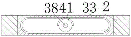
The invention relates to a replaceable automatic stamping die, which comprises a box body 1, wherein a cavity 12 with a leftward opening is arranged in the box body 1, the lower end wall of the cavity 12 is rotatably connected with a first rotating shaft 25, the upper end of the first rotating shaft 25 is slidably connected with a circular rotating disc 14 through a connecting device, 3 die slots 13 are uniformly distributed on the upper end wall of the circular rotating disc 14, a rectangular clamping slot 75 is arranged at the center of the circular rotating disc 14, second sliding slots 18 are symmetrically arranged on the left side and the right side of the first rotating shaft 25 on the lower end wall of the cavity 12, a top block 15 is in sliding fit with the second sliding slots 18, a first spring 17 fixedly connected with the top block 15 is arranged on the bottom wall of the second sliding slots 18, a first movable cavity 22 is arranged on the lower end wall of the cavity 12, the lower end of the first rotating shaft 25 extends into the first movable cavity 22 to be rotatably connected with the lower end wall of the first movable cavity 22, and a, be equipped with transmission chamber 65 in the cavity 12 upper end wall, transmission chamber 65 upper end wall fixedly connected with third motor 56, third motor 56 power connection second screw rod 58, second screw rod 58 lower extreme rotates to be connected transmission chamber 65 lower end wall, on the second screw rod 58 threaded connection with transmission chamber 65 sliding fit's second movable block 57, second movable block 57 rotates and is connected with third pivot 59, third pivot 59 sliding fit with cavity 12 with wall body between the transmission chamber 65 and in fixedly connected with rectangle fixture block 60 in the cavity 12, transmission chamber 65 upper end is equipped with first slip chamber 3, first slip chamber 3 upper end is equipped with third activity chamber 36, third activity chamber 36 upper end wall fixedly connected with second motor 34, second motor 34 power connection has first transmission shaft 38, first transmission shaft 38 lower extreme rotate connect in third activity chamber 36 with wall body between the first slip chamber 3 A half gear 41 is fixedly connected in the first sliding cavity 3, a clamping device is arranged in the first sliding cavity 3, the first transmission shaft 38 is fixedly connected in the third movable cavity 36 with a first belt wheel 40, the first belt wheel 40 is connected with a second belt wheel 44 through a first transmission belt 42, the right end of the third movable cavity 36 is connected with a fourth movable cavity 46, the second belt wheel 44 is fixedly connected in the fourth movable cavity 46 with a second transmission shaft 45, the second transmission shaft 45 is rotatably connected with the upper end wall of the fourth movable cavity 46, a third trapezoidal block 47 is arranged on the second transmission shaft 45, the third trapezoidal block 47 is slidably connected with a sixth helical gear 48, the left side of the sixth helical gear 48 is engaged with a fifth helical gear 43, the fifth helical gear 43 is fixedly connected with a crank rocker 66, the crank rocker 66 is connected with a stamping device, a second T-shaped ring groove 49 is arranged at the lower end of the sixth clamping wheel 48, the second T-shaped ring groove 49 is slidably connected with the second connecting rod 50, a fifth movable cavity 68 is arranged at the lower end of the fourth movable cavity 46, and an auxiliary connecting device is arranged in the fifth movable cavity 68.
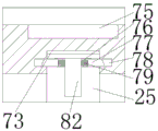
Advantageously, the connecting device comprises a connecting groove 73 located on the bottom wall of the circular rotating disk 14, the connecting groove 73 is slidably engaged with the first rotating shaft 25, the left and right end walls of the connecting groove 73 are symmetrically provided with second sliding grooves 78, the upper end of the first rotating shaft 25 is provided with a first sliding groove 76, a first electromagnet 82 is fixedly connected in the first sliding groove 76, the left and right ends of the first sliding groove 76 are slidably engaged with a sliding block 77 with inclined planes, and the sliding block 77 is connected with the first electromagnet 82 through a third spring 77.
Beneficially, the transmission device includes a worm 30 rotatably connected in the left end wall of the first movable chamber 22, a hydraulic chamber 21 is arranged at the lower side of the first movable chamber 22, a first piston plate 20 is arranged at the upper end of the hydraulic chamber 21, a first ram 19 is fixedly connected to the upper end of the first piston plate 20, the upper end of the first ram 19 passes through the upper end wall of the hydraulic chamber 21 and extends into the first sliding groove 18, a second piston plate 23 is arranged at the upper end of the right side of the hydraulic chamber 21, a second ram 24 is fixedly connected to the upper end of the second piston plate 23, the upper end of the second ram 24 passes through the upper end wall of the hydraulic chamber 21 and extends into the first movable chamber 22, a first trapezoidal block 26 is fixedly connected in the first movable chamber 22 by the first rotating shaft 25, a turbine 28 is slidably fitted in the first trapezoidal block 26, the rear end of the turbine 28 engages with the worm 30, a first T-shaped ring 27 is arranged at the lower end of the turbine 28, the lower end of the first T-shaped ring groove 27 is slidably connected with the second ejector rod 24, the right end of the first movable cavity 22 is provided with a second movable cavity 32, the right end of the worm 30 extends into the second movable cavity 32 and is rotatably connected with a wall body between the first movable cavity 22 and the second movable cavity 32, the worm 30 is fixedly connected with a first helical gear 29 in the second movable cavity 32, the lower end of the second transmission shaft 45 extends into the second movable cavity 32 and is rotatably connected with a wall body between the second movable cavity 32 and the fourth movable cavity 46, the lower end of the second transmission shaft 45 is fixedly connected with a second trapezoidal block 31 in the second movable cavity 32, the second trapezoidal block 31 is slidably matched with a second helical gear 55, and the upper end of the second helical gear 55 is provided with a third T-shaped ring groove 54.
Beneficially, the clamping device comprises an annular rack 33 in sliding fit with the first sliding cavity 3, the clamping device realizes a feeding function at the front end of the annular rack 33, the clamping device realizes a discharging function at the rear end of the annular rack 33, the inner side of the annular rack 33 is engaged with the half gear 41, a second sliding cavity 6 is arranged at the lower end of the first sliding cavity 3, a first chute 9 is arranged at the lower end of the second sliding cavity 6, a first fixed block 2 is symmetrically and fixedly connected with the front end and the rear end of the annular rack 33, a first screw 5 is rotatably connected with the lower end wall of the first fixed block 2, the first screw 5 extends into the second sliding cavity 6, a second fixed block 8 is in sliding fit with the second sliding cavity 6, a first motor 7 is fixedly connected with the upper end wall of the second fixed block 8, and the first motor 7 is in power connection with the first screw 5, the first screw rod 5 is provided with a first movable block 4 in a threaded fit mode, the first movable block 4 is fixedly connected with a first connecting rod 10, and the lower end of the first connecting rod 10 is fixedly connected with a second electromagnet 11.
Advantageously, the second rotary chamber 35 is provided on the left side of the fourth movable chamber 46, the punching device comprises a rocker 62 rotatably connected to the crank rocker 66, the lower end of the rocker 63 is rotatably connected to a fourth connecting rod 71, the lower end of the fourth connecting rod 71 is slidably connected to the wall between the second rotary chamber 35 and the cavity 12, and the lower end of the fourth connecting rod 71 is fixedly connected to a punching head 72 in the cavity 12.
Advantageously, a rotating groove 51 is formed on the right end wall of the cavity 12, the secondary transmission device includes a fourth rotating shaft 74 rotatably connected to the lower end wall of the rotating groove 51, the fourth rotating shaft 74 is fixedly connected to the roller 52 in the rotating groove 51, the roller 52 is in rolling connection with the circular turntable 14, the fourth rotating shaft 74 extends into the fifth movable cavity 68 and is rotatably connected to the upper end wall of the fifth movable cavity 68, the fourth rotating shaft 74 is in spline connection with a spline sleeve 70 in the fifth movable cavity 68, the spline sleeve 70 is fixedly connected to a first movable plate 69, the first movable plate 69 is in sliding fit with the fifth movable cavity 68, the upper end wall of the first movable plate 69 is connected to the U-shaped rack 67 through a second spring 63, the upper end of the first movable plate 69 is fixedly connected to the second connecting rod 50, the lower broken wall of the first movable plate 69 is fixedly connected to a third connecting rod 53, the lower end of the third connecting rod 53 extends into the second movable cavity 32 and is connected with the third annular groove 54 in a sliding manner.
Advantageously, the elastic force of the first spring 17 is greater than the gravity of the top block 15, and the discharging clamp and the receiving clamp work simultaneously.
In the initial state, the first motor 7, the second motor 34 and the third motor 56 stop rotating, the first movable plate 69 is located at the bottom 68 of the fifth movable cavity, the first trapezoidal block 26 is in contact with the turbine 28, and the second trapezoidal block 31 is in contact with the second bevel gear 55;
when the work is started, the first motor 7 is started, the first screw 5 rotates to drive the first connecting rod 10 to move downwards through the first movable block 4, the first connecting rod 10 drives the first electromagnet 11 to move downwards to adsorb a workpiece, the first motor 7 rotates reversely to drive the workpiece to move upwards, the second motor 34 is started, the first transmission shaft 28 drives the first belt pulley 40 and the half gear 41 to rotate, the half gear 41 drives the first fixed block 2 to reciprocate in the horizontal direction through the annular rack 33, the discharging clamp places the workpiece into the die slot 13, the receiving clamp takes the workpiece out of the die slot 13, the first belt pulley 40 drives the second belt pulley 44 to rotate through the first transmission belt 42, the second belt pulley 44 drives the second helical gear 55 to rotate through the second transmission shaft 45, the second bevel gear 55 drives the worm gear 30 to rotate through the first bevel gear 29, the worm gear 30 drives the worm wheel 28 to rotate, the worm wheel 28 drives the circular turntable 14 to rotate through the first rotating shaft 25, the first electromagnet 11 places a workpiece in the mold cavity 13, the first electromagnet 11 and the circular turntable 14 drive the roller 52 to rotate, the roller 52 drives the first movable plate 69 to move upwards through the fourth rotating shaft 74 and the spline sleeve 70, the first movable plate 69 drives the U-shaped rack 67, the second connecting rod 50 and the third connecting rod 53 to move upwards, the U-shaped rack 67 engages with the second half gear 64, the third connecting rod 53 drives the second bevel gear 55 to move upwards, the circular turntable 14 stops rotating, and the second connecting rod 50 drives the sixth bevel gear 48 to move upwards, said sixth helical gear 48 and said fifth helical gear 43 mesh, said sixth helical gear 48 and said third trapezoidal block 47 cooperate, the second transmission shaft 45 drives the crank rocker 66 to rotate through the sixth bevel gear 48 and the fifth bevel gear 45, the crank rocker 66 drives the punch 72 to perform punching operation through the rocker 62 and the fourth connecting rod 71, the crank rocker 66 drives the U-shaped rack 67 to move upwards and then return to move downwards through the half gear 64, when the U-shaped rack moves downwards, the first movable plate 69 is driven to move downwards, the first movable plate 69 drives the second connecting rod 50 and the third connecting rod 53 to move, the sixth bevel gear 48 and the fifth bevel gear 45 are separated, the second bevel gear 55 and the first bevel gear 29 are engaged, and the circular turntable 14 continues to rotate.
When the mold needs to be replaced, the third motor 56 is started, the second screw 58 rotates to drive the second movable block 57 to move upwards, the second movable block 57 drives the rectangular fixture block 60 to move upwards through the third rotating shaft 69 to leave the rectangular fixture groove 75, the third click 56 stops rotating, the second electromagnet 82 is started, the slider 77 is adsorbed to leave the second sliding groove 78, the first spring 17 drives the circular turntable 14 to move upwards by pushing the top block 15, the first rotating shaft 25 leaves the connecting groove 73, the second electromagnet 82 stops working, a worker takes down the circular turntable 14 and puts the circular turntable into a new turntable, the third motor 56 is started in the reverse direction, the third rotating shaft 69 drives the rectangular fixture block 60 to move downwards to drive the circular turntable 14 to move downwards, and the first rotating shaft 25 extends into the connecting groove 73, the slider 77 is moved rightward into the second slide groove 78 by the third spring 79.
The above description is only an embodiment of the invention, but the scope of the invention is not limited thereto, and any changes or substitutions that are not thought of through the inventive work should be included in the scope of the invention. Therefore, the protection scope of the invention should be subject to the protection scope defined by the claims.
Claims (7)
1. A replaceable automatic stamping die comprises a box body, wherein a cavity with a left opening is formed in the box body, a first rotating shaft is rotatably connected to the lower end wall of the cavity, a circular rotating disc is slidably connected to the upper end of the first rotating shaft through a connecting device, three die grooves are uniformly formed in the upper end wall of the circular rotating disc, a rectangular clamping groove is formed in the center of the circular rotating disc, second sliding grooves are symmetrically formed in the left side and the right side of the first rotating shaft on the lower end wall of the cavity, a jacking block is slidably matched in the second sliding grooves, a first spring fixedly connected with the jacking block is mounted on the bottom wall of the second sliding grooves, a first movable cavity is formed in the lower end wall of the cavity, the lower end of the first rotating shaft extends into the first movable cavity to be rotatably connected with the lower end wall of the first movable cavity, a transmission device is arranged in the first movable cavity, a transmission cavity is formed in the upper end wall of the cavity, the third motor is in power connection with a second screw rod, the lower end of the second screw rod is in rotating connection with the lower end wall of the transmission cavity, a second movable block in sliding fit with the transmission cavity is in threaded connection with the second screw rod, the second movable block is in rotating connection with a third rotating shaft, the third rotating shaft is in sliding fit with a wall body between the cavity and the transmission cavity, a rectangular clamping block is fixedly connected in the cavity, a first sliding cavity is arranged at the upper end of the transmission cavity, a third movable cavity is arranged at the upper end of the first sliding cavity, a second motor is fixedly connected with the upper end wall of the third movable cavity, the second motor is in power connection with a first transmission shaft, the lower end of the first transmission shaft is in rotating connection with the wall body between the third movable cavity and the first sliding cavity, a half gear is fixedly connected in the first sliding cavity, and a clamping device is arranged in the first sliding cavity, the first transmission shaft is fixedly connected with a first belt wheel in the third movable cavity, the first belt wheel is connected with a second belt wheel through a first conveyor belt, the right end of the third movable cavity is connected with a fourth movable cavity, the second belt wheel is fixedly connected with a second transmission shaft in the fourth movable cavity, the second transmission shaft is rotatably connected with the upper end wall of the fourth movable cavity, a third trapezoidal block is arranged on the second transmission shaft, the third trapezoidal block is connected with a sixth bevel gear in a sliding way, the left side of the sixth bevel gear is meshed with a fifth bevel gear, the fifth bevel gear is fixedly connected with a crank rocker, the crank rocker is connected with a stamping device, the lower end of the sixth clamping wheel is provided with a second T-shaped annular groove, the second T-shaped ring groove is connected with a second connecting rod in a sliding mode, a fifth movable cavity is arranged at the lower end of the fourth movable cavity, and an auxiliary connecting device is arranged in the fifth movable cavity.
2. The replaceable automatic stamping die of claim 1, wherein: connecting device is including being located the spread groove of circular carousel diapire, spread groove sliding fit first pivot, the spread groove left and right sides end wall symmetry is equipped with the second sliding tray, first pivot upper end is equipped with first sliding tray, the first electro-magnet of fixedly connected with in the first sliding tray, the left and right ends sliding fit of first spout has the slider that has the inclined plane, the slider passes through third spring coupling first electro-magnet.
3. The replaceable automatic stamping die of claim 1, wherein: the transmission device comprises a worm rotatably connected in the left end wall of the first movable cavity, a hydraulic cavity is arranged at the lower side of the first movable cavity, a first piston plate is arranged at the upper end of the side of the hydraulic cavity, a first ejector rod is fixedly connected to the upper end of the first piston plate, the upper end of the first ejector rod penetrates through the upper end wall of the hydraulic cavity and extends into the first chute, a second piston plate is arranged at the upper end of the right side of the hydraulic cavity, a second ejector rod is fixedly connected to the upper end of the second piston plate, the upper end of the second ejector rod penetrates through the upper end wall of the hydraulic cavity and extends into the first movable cavity, a first trapezoidal block is fixedly connected to the first movable cavity through the first rotating shaft, a turbine is in sliding fit with the first trapezoidal block, the rear end of the turbine is meshed with the worm, a first T-shaped annular groove is arranged at the lower end of the turbine, and is in sliding connection with the, the first movable cavity right-hand member is equipped with the second activity chamber, the worm right-hand member stretch into the second activity chamber and with first activity chamber with wall body rotation connection between the second activity chamber, the worm in the second rotates the intracavity fixedly connected with first helical gear, second transmission shaft lower extreme stretch into the second activity chamber and with the second activity chamber with wall body rotation connection between the fourth activity chamber, second transmission shaft lower extreme in the second activity intracavity fixedly connected with second trapezoidal piece, second trapezoidal piece sliding fit has the second helical gear, second helical gear upper end is equipped with third T shape annular.
4. The replaceable automatic stamping die of claim 1, wherein: the clamping device comprises an annular rack in sliding fit with the first sliding cavity, the clamping device realizes a feeding function at the front end of the annular rack, the clamping device realizes a discharging function at the rear end of the annular rack, the inner side of the annular rack is meshed with the half gear, a second sliding cavity is arranged at the lower end of the first sliding cavity, a first sliding chute is arranged at the lower end of the second sliding cavity, the front end and the rear end of the annular rack are symmetrically and fixedly connected with a first fixed block, the lower end wall of the first fixed block is rotationally connected with a first screw rod, the first screw rod extends into the second sliding cavity, a second fixed block is in sliding fit with the second sliding cavity, a first motor is fixedly connected with the upper end wall of the second fixed block, the first motor is in power connection with the first screw rod, a first movable block is in threaded fit with the first screw rod, and a first connecting rod is movably and fixedly connected with the first connecting rod, and the lower end of the first connecting rod is fixedly connected with a second electromagnet.
5. The replaceable automatic stamping die of claim 1, wherein: the stamping device comprises a crank rocker, a first connecting rod, a second connecting rod, a wall body, a stamping head and a stamping device, wherein the first connecting rod is connected with the cavity, the stamping device is connected with the wall body, the second connecting rod is connected with the cavity, the stamping device comprises a rocker which is rotatably connected with the crank rocker, the lower end of the rocker is rotatably connected with the fourth connecting rod, the lower end of the fourth connecting rod is slidably connected with the wall body between the first rotating cavity and the cavity, and the.
6. The replaceable automatic stamping die of claim 1, wherein: a rotating groove is arranged on the right end wall of the cavity, the auxiliary transmission device comprises a fourth rotating shaft which is rotatably connected with the lower end wall of the rotating groove, the fourth rotating shaft is fixedly connected with a roller in the rotating groove, the roller is connected with the circular turntable in a rolling way, the fourth rotating shaft extends into the fifth movable cavity and is rotatably connected with the upper end wall of the fifth movable cavity, the fourth rotating shaft is connected with a spline sleeve in the fifth movable cavity through a spline, the spline sleeve is fixedly connected with the first movable plate, the first movable plate is in sliding fit with the fifth movable cavity, the upper end wall of the first movable plate is connected with the U-shaped rack through a second spring, the upper end of the first movable plate is fixedly connected with the second connecting rod, the lower broken wall of the first movable plate is fixedly connected with a third connecting rod, and the lower end of the third connecting rod extends into the second movable cavity and is connected with the third annular groove in a sliding mode.
7. The replaceable automatic stamping die of claim 1, wherein: the elasticity of the first spring is greater than the gravity of the ejector block, and the discharging clamp and the receiving clamp work simultaneously.
Priority Applications (1)
| Application Number | Priority Date | Filing Date | Title |
|---|---|---|---|
| CN202010080130.6A CN111112478A (en) | 2020-02-04 | 2020-02-04 | Replaceable automatic stamping die |
Applications Claiming Priority (1)
| Application Number | Priority Date | Filing Date | Title |
|---|---|---|---|
| CN202010080130.6A CN111112478A (en) | 2020-02-04 | 2020-02-04 | Replaceable automatic stamping die |
Publications (1)
| Publication Number | Publication Date |
|---|---|
| CN111112478A true CN111112478A (en) | 2020-05-08 |
Family
ID=70492814
Family Applications (1)
| Application Number | Title | Priority Date | Filing Date |
|---|---|---|---|
| CN202010080130.6A Withdrawn CN111112478A (en) | 2020-02-04 | 2020-02-04 | Replaceable automatic stamping die |
Country Status (1)
| Country | Link |
|---|---|
| CN (1) | CN111112478A (en) |
Cited By (2)
| Publication number | Priority date | Publication date | Assignee | Title |
|---|---|---|---|---|
| CN112165230A (en) * | 2020-09-30 | 2021-01-01 | 台州市金维达电机有限公司 | Motor assembling machine |
| CN114232816A (en) * | 2021-12-28 | 2022-03-25 | 江苏诚意住宅工业科技发展有限公司 | Novel prefabricated frame structure and assembling method thereof |
-
2020
- 2020-02-04 CN CN202010080130.6A patent/CN111112478A/en not_active Withdrawn
Cited By (3)
| Publication number | Priority date | Publication date | Assignee | Title |
|---|---|---|---|---|
| CN112165230A (en) * | 2020-09-30 | 2021-01-01 | 台州市金维达电机有限公司 | Motor assembling machine |
| CN114232816A (en) * | 2021-12-28 | 2022-03-25 | 江苏诚意住宅工业科技发展有限公司 | Novel prefabricated frame structure and assembling method thereof |
| CN114232816B (en) * | 2021-12-28 | 2023-11-10 | 江苏诚意住宅工业科技发展有限公司 | Prefabricated assembled frame structure and assembling method thereof |
Similar Documents
| Publication | Publication Date | Title |
|---|---|---|
| CN211027822U (en) | Automatic stamping equipment for sheet stamping | |
| CN111112478A (en) | Replaceable automatic stamping die | |
| CN110202465B (en) | Stamping die surface finish device | |
| CN207839871U (en) | Feed mechanism in a kind of double-station die | |
| CN216937890U (en) | Indentation device of automobile punching part | |
| CN116274518A (en) | One-step forming equipment for bending and corner cutting of signal disc frame and forming method thereof | |
| CN110744308A (en) | Metal pipeline bending cutting machine | |
| CN212552677U (en) | Double-hole outgoing line type coil shell machining equipment | |
| CN211218218U (en) | Open type press | |
| CN212469812U (en) | Drilling device for machining non-standard parts of mechanical equipment | |
| CN219274261U (en) | Stamping device | |
| CN218656319U (en) | Punch press with guide structure | |
| CN218574709U (en) | Stamping die convenient to location | |
| CN116851580A (en) | Punching machine for machining and manufacturing | |
| CN116237408A (en) | Machining machine for mechanical forming manufacturing | |
| CN111906638B (en) | Tapping processing equipment of die-casting power pack | |
| CN111975063B (en) | Numerical control double-table-changing precision plane milling machine capable of automatically sensing and clamping workpieces | |
| CN108480483A (en) | A kind of punching die device | |
| CN212264217U (en) | Automatic shaping device for metal corrugated pipe | |
| CN208825745U (en) | A kind of Semi-automatic arc cutter device | |
| CN114905269A (en) | Screw assembly machine for electric appliance assembly | |
| CN112191733A (en) | Sheet metal part blanking die | |
| CN113909553A (en) | High-strength cold-rolled sheet processing equipment for automobile | |
| CN111844227A (en) | Automatic feeding auxiliary device for punching building energy-saving plate | |
| CN111633118A (en) | Stamping equipment for socket insertion sheet |
Legal Events
| Date | Code | Title | Description |
|---|---|---|---|
| PB01 | Publication | ||
| PB01 | Publication | ||
| SE01 | Entry into force of request for substantive examination | ||
| SE01 | Entry into force of request for substantive examination | ||
| WW01 | Invention patent application withdrawn after publication |
Application publication date: 20200508 |
|
| WW01 | Invention patent application withdrawn after publication |