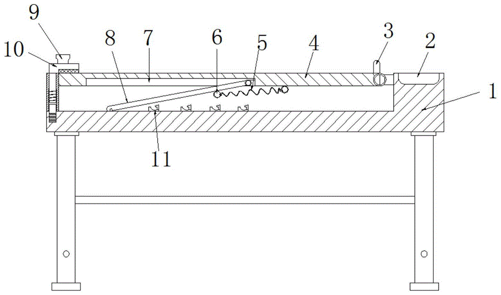
Drawing table for interior decoration design
Technical Field
The invention relates to the technical field of drawing tables, in particular to a drawing table for interior decoration design.
Background
Indoor design refers to the preparation of a particular material for technical, economic, etc. limited feasibility, to meet certain building objectives (including human requirements for its intended function, visual perception). Requires knowledge in engineering and also artistic theory and skills.
People generally use drawing workbenches when performing indoor design work. If need carry out angle modulation work with the drawing board when using manual drawing, convenient drawing, current drawing workstation has some not enough in the use, and inconvenient fixes a position the fixed work to the drawing board after accomodating.
Disclosure of Invention
The invention aims to solve the defects in the prior art and provides a drawing table for interior decoration design.
In order to achieve the purpose, the invention adopts the following technical scheme:
the utility model provides a drawing bench for interior decoration design, includes the base station, base station top outer wall is opened has the groove of accomodating, and accomodate groove one side inner wall and rotate and install the drawing board, and drawing board bottom outer wall is opened there is the mounting groove, and the mounting groove internal rotation installs the bracing piece, accomodates the bottom of the groove inner wall and is fixed with a plurality ofly and forms joint complex locating piece with the bracing piece bottom, the left side outer wall of drawing board is fixed with the curb plate, and curb plate bottom outer wall is opened there is the guide way, and the activity is pegged graft in the guide way has the round pin axle, and the round pin axle top is passed curb plate top outer wall and is fixed with the grip block, sell epaxial being fixed with the spacing ring of guide way inner wall laminating, and being fixed with reset spring on the spacing ring, reset spring cup joints at the round pin epaxially, round pin axle circumference.
Furthermore, a handle strip is fixed at the top of the clamping plate, and a protective pad is bonded on the clamping surface of the clamping plate.
Furthermore, a supporting mechanism is fixed on the outer wall of the bottom of the base station.
Furthermore, a barrier strip is fixed on the right side of the outer wall of the top of the drawing board.
Furthermore, a storage groove is formed in the right side of the outer wall of the top of the base station.
Furthermore, all be fixed with solid fixed ring on bracing piece and the drawing board, be fixed with same connecting spring on two solid fixed rings.
Further, the positioning blocks are deleted, the inner wall of the bottom of the accommodating groove is further fixedly provided with a motor, a screw rod is fixedly arranged on an output shaft of the motor, a sliding block is sleeved on the screw rod in a threaded manner, and the top of the sliding block and the bottom end of the supporting rod are rotatably installed.
The invention has the beneficial effects that:
1. set up through the grip block can be in pulling upward movement when handle strip, and then drive the round pin axle and take out in the constant head tank, the spacing ring compresses reset spring, place drawing paper edge and loosen behind the grip block below, reset spring drives the grip block and carries out the centre gripping fixed action to drawing paper, take out the round pin axle after the connecting spring shrink drive bracing piece anticlockwise rotation, make the drawing board left end perk, avoid the round pin axle to insert inside the constant head tank again, the rotation support pole makes its angle location work of pegging graft and carrying out the drawing board in the constant head tank, facilitate the use, the round pin axle is pegged graft in the constant head tank when the drawing board is in the horizontal state of accomodating, the rubber circle can increase the frictional resistance of round pin axle and constant head tank in addition, avoid the round pin axle to break.
2. Through the setting of slider can be under the drive of motor and screw rod lateral motion, the slider and then drives bracing piece bottom lateral motion for the bracing piece carries out the regulation of drawing angle, convenient and fast to the drawing board.
Drawings
Fig. 1 is a schematic cross-sectional structural view of an embodiment 1 of a drawing table for interior decoration design according to the present invention;
FIG. 2 is a schematic view of a pin shaft of a drawing table for interior decoration design according to the present invention;
fig. 3 is a schematic perspective view of a pin shaft of a drawing table for interior decoration design according to the present invention;
fig. 4 is a schematic cross-sectional structure diagram of an embodiment 2 of a drawing table for interior decoration design according to the present invention.
In the figure: 1 base station, 2 put the thing groove, 3 blend stops, 4 drawing boards, 5 connecting spring, 6 solid fixed ring, 7 mounting grooves, 8 bracing pieces, 9 handle strips, 10 grip blocks, 11 locating pieces, 12 curb plates, 13 round pin axles, 14 reset spring, 15 spacing rings, 16 guide ways, 17 rubber rings, 18 constant head tank, 19 sliders, 20 screw rods, 21 motors.
Detailed Description
The technical solutions in the embodiments of the present invention will be clearly and completely described below with reference to the drawings in the embodiments of the present invention, and it is obvious that the described embodiments are only a part of the embodiments of the present invention, and not all of the embodiments.
Examples of which are illustrated in the accompanying drawings, wherein like reference numerals refer to the same or similar elements or elements having the same or similar function throughout. The embodiments described below with reference to the drawings are exemplary only for the purpose of explaining the present patent and are not to be construed as limiting the present patent.
Example 1
Referring to fig. 1-3, a drawing table for interior decoration design comprises a base table 1, a receiving groove is formed on the outer wall of the top of the base table 1, and the inner wall of one side of the containing groove is rotatably provided with a drawing board 4, the outer wall of the bottom of the drawing board 4 is provided with an installing groove 7, a supporting rod 8 is rotatably arranged in the mounting groove 7, a plurality of positioning blocks 11 which are in clamping fit with the bottom end of the supporting rod 8 are fixed on the inner wall of the bottom of the accommodating groove, a side plate 12 is fixed on the outer wall of the left side of the drawing board 4, a guide groove 16 is arranged on the outer wall of the bottom of the side plate 12, a pin shaft 13 is movably inserted in the guide groove 16, a clamping plate 10 is fixed at the top end of the pin shaft 13 which penetrates through the outer wall of the top of the side plate 12, a limiting ring 15 which is attached to the inner wall, a return spring 14 is fixed on the limit ring 15, the return spring 14 is sleeved on the pin shaft 13, a plurality of rubber rings 17 are fixed at the bottom end of the circumferential outer wall of the pin shaft 13, and the left side of the outer wall of the bottom of the accommodating groove is provided with a positioning groove 18 which is in insertion fit with the pin shaft 13.
The top of grip block 10 is fixed with handle strip 9, and the clamping face of grip block 10 bonds and has the protection pad, and 1 bottom outer wall of base station is fixed with supporting mechanism, and 4 top outer wall right sides of drawing board are fixed with blend stop 3, and 1 top outer wall right sides of base station are opened and are put thing groove 2 bracing piece 8 and drawing board 4 and all be fixed with solid fixed ring 6, are fixed with same coupling spring 5 on two solid fixed ring 6.
The working principle of the embodiment is as follows: grip block 10 can be in pulling handle strip 9 time upward movement, and then drive round pin axle 13 and take out from constant head tank 18, spacing ring 15 compresses reset spring 14, place drawing paper edge and loosen behind grip block 10 below, reset spring 14 drives grip block 10 and carries out centre gripping fixed action to drawing paper, take out round pin axle 13 back coupling spring 5 shrink and drive 8 anticlockwise rotations of bracing piece, make 4 left ends perk of drawing board, avoid round pin axle 13 to insert inside constant head tank 18 again, rotation support rod 8 makes its angle location work of pegging graft and carrying out drawing board 4 in locating piece 11, facilitate the use, round pin axle 13 pegs graft in constant head tank 18 when drawing board 4 is the level and accomodates the state, rubber ring 17 can increase the frictional resistance of round pin axle 13 and constant head tank 18 in addition, avoid round pin axle 13 to break away from constant head tank 18, improve the stability of accomodating work.
Example 2
Referring to fig. 4, a drawing table for interior decoration design, the difference between this embodiment and embodiment 1 is that the positioning block 11 is removed, the inner wall of the bottom of the accommodating groove is further fixed with a motor 21, the output shaft of the motor 21 is fixed with a screw rod 20, the screw rod 20 is in threaded sleeve connection with a slide block 19, and the top of the slide block 19 is rotatably installed with the bottom end of the support rod 8.
The working principle of the embodiment is as follows: slider 19 can be at motor 21 and screw rod 20's drive lateral motion down, and slider 19 and then drives 8 bottom lateral motion of bracing pieces for bracing piece 8 carries out the regulation of drawing angle, convenient and fast to drawing board 4.
In the description of this patent, it is to be understood that the terms "coaxial," "bottom," "one end," "top," "middle," "other end," "upper," "one side," "top," "inner," "front," "center," "two ends," and the like are used in the orientations and positional relationships indicated in the drawings for convenience in describing the patent and for simplicity in description, and are not intended to indicate or imply that the referenced device or element must have a particular orientation, be constructed and operated in a particular orientation, and are not to be considered limiting of the patent.
In this patent, unless expressly stated or limited otherwise, the terms "mounted," "disposed," "connected," "secured," "screwed" and the like are to be construed broadly and can, for example, be fixedly connected, detachably connected, or integrally formed; can be mechanically or electrically connected; they may be directly connected or indirectly connected through an intermediate, or they may be connected internally or in an interactive relationship with each other, and unless otherwise specifically limited, the specific meaning of the above terms in this patent will be understood by those skilled in the art according to the specific circumstances.
The above description is only for the preferred embodiment of the present invention, but the scope of the present invention is not limited thereto, and any person skilled in the art should be considered to be within the technical scope of the present invention, and the technical solutions and the inventive concepts thereof according to the present invention should be equivalent or changed within the scope of the present invention.