CN110979035A - A trolley that can walk on the variable diameter arc surface of cement rotary kiln - Google Patents

A trolley that can walk on the variable diameter arc surface of cement rotary kiln Download PDF

Info

Publication number
CN110979035A
CN110979035A CN201911385055.8A CN201911385055A CN110979035A CN 110979035 A CN110979035 A CN 110979035A CN 201911385055 A CN201911385055 A CN 201911385055A CN 110979035 A CN110979035 A CN 110979035A
Authority
CN
China
Prior art keywords
wheel
trolley
body frame
kiln
diameter
Prior art date
Legal status (The legal status is an assumption and is not a legal conclusion. Google has not performed a legal analysis and makes no representation as to the accuracy of the status listed.)
Pending
Application number
CN201911385055.8A
Other languages
Chinese (zh)
Inventor
杨志凯
汪步云
许德章
邓启超
李公文
Current Assignee (The listed assignees may be inaccurate. Google has not performed a legal analysis and makes no representation or warranty as to the accuracy of the list.)
Anhui Polytechnic University
Wuhu Anpu Robot Industry Technology Research Institute Co Ltd
Original Assignee
Anhui Polytechnic University
Wuhu Anpu Robot Industry Technology Research Institute Co Ltd
Priority date (The priority date is an assumption and is not a legal conclusion. Google has not performed a legal analysis and makes no representation as to the accuracy of the date listed.)
Filing date
Publication date
Application filed by Anhui Polytechnic University, Wuhu Anpu Robot Industry Technology Research Institute Co Ltd filed Critical Anhui Polytechnic University
Priority to CN201911385055.8A priority Critical patent/CN110979035A/en
Publication of CN110979035A publication Critical patent/CN110979035A/en
Pending legal-status Critical Current

Links

Images

Classifications

    • B—PERFORMING OPERATIONS; TRANSPORTING
    • B60—VEHICLES IN GENERAL
    • B60L—PROPULSION OF ELECTRICALLY-PROPELLED VEHICLES; SUPPLYING ELECTRIC POWER FOR AUXILIARY EQUIPMENT OF ELECTRICALLY-PROPELLED VEHICLES; ELECTRODYNAMIC BRAKE SYSTEMS FOR VEHICLES IN GENERAL; MAGNETIC SUSPENSION OR LEVITATION FOR VEHICLES; MONITORING OPERATING VARIABLES OF ELECTRICALLY-PROPELLED VEHICLES; ELECTRIC SAFETY DEVICES FOR ELECTRICALLY-PROPELLED VEHICLES
    • B60L50/00—Electric propulsion with power supplied within the vehicle
    • B60L50/50—Electric propulsion with power supplied within the vehicle using propulsion power supplied by batteries or fuel cells
    • B60L50/60—Electric propulsion with power supplied within the vehicle using propulsion power supplied by batteries or fuel cells using power supplied by batteries
    • B—PERFORMING OPERATIONS; TRANSPORTING
    • B60—VEHICLES IN GENERAL
    • B60G—VEHICLE SUSPENSION ARRANGEMENTS
    • B60G21/00—Interconnection systems for two or more resiliently-suspended wheels, e.g. for stabilising a vehicle body with respect to acceleration, deceleration or centrifugal forces
    • B60G21/007—Interconnection systems for two or more resiliently-suspended wheels, e.g. for stabilising a vehicle body with respect to acceleration, deceleration or centrifugal forces means for adjusting the wheel inclination
    • B—PERFORMING OPERATIONS; TRANSPORTING
    • B60—VEHICLES IN GENERAL
    • B60G—VEHICLE SUSPENSION ARRANGEMENTS
    • B60G21/00—Interconnection systems for two or more resiliently-suspended wheels, e.g. for stabilising a vehicle body with respect to acceleration, deceleration or centrifugal forces
    • B60G21/02—Interconnection systems for two or more resiliently-suspended wheels, e.g. for stabilising a vehicle body with respect to acceleration, deceleration or centrifugal forces permanently interconnected
    • B60G21/04—Interconnection systems for two or more resiliently-suspended wheels, e.g. for stabilising a vehicle body with respect to acceleration, deceleration or centrifugal forces permanently interconnected mechanically
    • B—PERFORMING OPERATIONS; TRANSPORTING
    • B60—VEHICLES IN GENERAL
    • B60G—VEHICLE SUSPENSION ARRANGEMENTS
    • B60G2200/00—Indexing codes relating to suspension types
    • B60G2200/40—Indexing codes relating to the wheels in the suspensions
    • B60G2200/422—Driving wheels or live axles
    • Y—GENERAL TAGGING OF NEW TECHNOLOGICAL DEVELOPMENTS; GENERAL TAGGING OF CROSS-SECTIONAL TECHNOLOGIES SPANNING OVER SEVERAL SECTIONS OF THE IPC; TECHNICAL SUBJECTS COVERED BY FORMER USPC CROSS-REFERENCE ART COLLECTIONS [XRACs] AND DIGESTS
    • Y02—TECHNOLOGIES OR APPLICATIONS FOR MITIGATION OR ADAPTATION AGAINST CLIMATE CHANGE
    • Y02T—CLIMATE CHANGE MITIGATION TECHNOLOGIES RELATED TO TRANSPORTATION
    • Y02T10/00—Road transport of goods or passengers
    • Y02T10/60—Other road transportation technologies with climate change mitigation effect
    • Y02T10/70—Energy storage systems for electromobility, e.g. batteries

Landscapes

  • Engineering & Computer Science (AREA)
  • Mechanical Engineering (AREA)
  • Life Sciences & Earth Sciences (AREA)
  • Sustainable Development (AREA)
  • Sustainable Energy (AREA)
  • Power Engineering (AREA)
  • Transportation (AREA)
  • Muffle Furnaces And Rotary Kilns (AREA)

Abstract

本发明涉及水泥回转窑变径弧面的行走领域,具体是一种可在水泥回转窑变径弧面行走的小车,包括用于支撑车轮的车身架以及设置在车身架上的控制装置和锂电供电装置,还包括:大型轮毂电机行走装置、车轮调节装置、避障装置,设置在车身架的前端面上,能对前方设定区域的障碍物进行感知识别,当安全距离内出现障碍物时,小车停车报警,保障小车的安全可靠,通过车轮调节装置使得小车能根据窑体直径的变化,自主调节车轮与车身夹角,适应窑体弧度,在窑体内行走时,能最大程度的减小对窑体的损伤,增大小车的承载、运输能力;在通过回转窑变径部分时,小车轮组前后独立调节,能让车轮始终贴合窑体。

Figure 201911385055

The invention relates to the walking field of the variable-diameter cambered surface of a cement rotary kiln, in particular to a trolley that can travel on the variable-diameter cambered surface of the cement rotary kiln, comprising a body frame for supporting wheels, a control device and a lithium battery power supply device arranged on the body frame , also includes: large in-wheel motor running device, wheel adjustment device, obstacle avoidance device, which are arranged on the front end of the body frame, and can sense and identify obstacles in the set area ahead. When obstacles appear within a safe distance, the car The parking alarm ensures the safety and reliability of the trolley. Through the wheel adjustment device, the trolley can independently adjust the angle between the wheel and the body according to the change of the diameter of the kiln body to adapt to the curvature of the kiln body. When walking in the kiln body, it can minimize the impact on the kiln body. The damage of the trolley increases the carrying and transportation capacity of the trolley; when passing through the variable diameter part of the rotary kiln, the trolley wheel group is independently adjusted front and rear, so that the wheels can always fit the kiln body.

Figure 201911385055

Description

Trolley capable of walking on reducing cambered surface of rotary cement kiln
Technical Field
The invention relates to the field of walking of a reducing cambered surface of a rotary cement kiln, in particular to a trolley capable of walking on the reducing cambered surface of the rotary cement kiln.
Background
The traditional rotary cement kiln is paved, detected, maintained and the like by manual work, the required equipment and raw materials are large in size and heavy in weight, and the rotary cement kiln can only be carried by manual work or a small forklift at present, so that the labor intensity is high; the kiln body is extruded by the forklift wheels, the safety of the forklift and the service life of tires are influenced, the kiln body is greatly damaged by reciprocating walking, and the transportation efficiency is limited; the cement clinker dust cleaning machine works in a toxic and harmful closed environment filled with cement clinker dust for a long time, and poses no small threat to the personal safety of workers. The existing of no effective special transport tool exists, and advanced technologies such as modern automatic laying devices for rotary cement kiln refractory bricks cannot be effectively carried out in a kiln body.
Disclosure of Invention
In order to solve the problems, the invention provides a trolley capable of walking on a reducing cambered surface of a rotary cement kiln.
The utility model provides a can be at dolly of rotary cement kiln reducing cambered surface walking, includes the automobile body frame that is used for supporting the wheel and sets up controlling means and the lithium electricity power supply unit on the automobile body frame, still includes:
the large-scale wheel hub motor walking device is arranged on the vehicle body frame, is matched with the wheels and is used for integrating power, transmission and braking into the wheel hubs of the wheels so that each wheel is driven independently;
the wheel adjusting devices are distributed at two ends of the vehicle body frame, and do circular arc motion in a vertical plane where the axis of the wheel is located by taking the connection point of the wheel and the vehicle frame as the center of a circle to adapt to the cambered surface profile of the variable-diameter kiln body part;
the obstacle avoidance device is arranged on the front end face of the vehicle body frame, can sense and identify obstacles in a front set area, and can give an alarm when the obstacles appear in a safe distance, so that the safety and the reliability of the vehicle are guaranteed.
The large-scale in-wheel motor walking device comprises a plurality of groups of driving supports arranged on the lower end face of the vehicle body frame, a hinge mechanism which enables wheels to be connected and matched with the driving supports, and in-wheel motors arranged on the wheels and used for driving the wheels to independently drive.
The wheel adjusting device comprises a servo motor, a double-output-shaft speed reducer which is matched with the servo motor to perform reverse transmission and is used for keeping walking stability, and a connecting rod sliding mechanism which is matched with the double-output-shaft speed reducer and is used for converting linear motion into rotary motion of the wheel shaft.
The servo motor on be provided with miniature revolving stage, miniature revolving stage on install the laser range finder of the circular arc diameter that accessible multiple spot position measurement reachd the walking, laser range finder can measure the diameter of the circular arc that the front and back wheelset belongs to respectively for the front and back wheelset can be according to the independent regulation of place cambered surface diameter and automobile body angle, can adapt to the walking requirement of reducing kiln body part.
The connecting rod sliding mechanism comprises a sliding rail arranged on the vehicle body frame, a sliding block matched with the sliding rail, a worm gear lead screw lifter arranged on the sliding block, and a telescopic coupler arranged on the worm gear lead screw lifter, wherein a wheel shaft is connected with the sliding block.
The double-output-shaft speed reducer and the worm-gear lead screw lifter realize synchronous adjustment of wheels on two sides, can adapt to the walking requirement of the arc surface of the kiln body, and keep the wheels and the tangent plane of the contact kiln body vertical all the time.
The obstacle avoidance device is composed of two laser obstacle avoidance sensors which sense and identify obstacles in a front set area and ensure the safety and reliability of the trolley.
The control device comprises a control mounting plate arranged on the vehicle body frame and an integrated control cabinet which is arranged on the control mounting plate, can complete the receiving and the calculation of signals and sends corresponding motion instructions to a driving and adjusting servo motor.
The lithium battery power supply device comprises a battery mounting frame arranged on the lower end face of the vehicle body frame and batteries which are arranged in the battery mounting frame and can respectively supply power to the large-scale hub motor walking device and the control device.
The invention has the beneficial effects that: the included angle between the wheels and the vehicle body can be automatically adjusted by the trolley through the wheel adjusting device according to the change of the diameter of the kiln body, the radian of the kiln body is adapted, the damage to the kiln body can be reduced to the greatest extent when the trolley travels in the kiln body, and the bearing and transportation capacity of the trolley is improved; when the rotary kiln passes through the variable-diameter part, the small wheel groups are independently adjusted front and back, so that the wheels can be always attached to the kiln body; the height difference generated by adjusting the wheel set can offset the height difference generated by reducing the kiln body, so that the vehicle body can be kept horizontal, modern operation equipment such as an automatic refractory brick laying device of a rotary cement kiln can be carried, and the working efficiency and quality of the rotary cement kiln in laying, detection and maintenance are improved.
Drawings
The invention is further illustrated with reference to the following figures and examples.
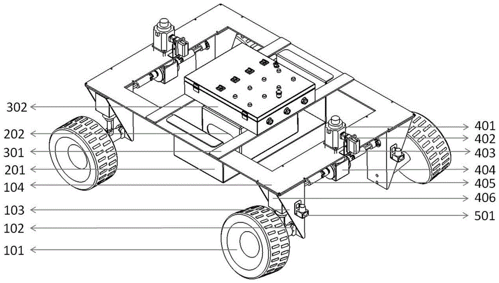
FIG. 1 is a schematic perspective view of the present invention;
FIG. 2 is a schematic side view of the present invention;
FIG. 3 is a schematic diagram of the present invention;
fig. 4 is a schematic top view of the present invention.
Detailed Description
In order to make the technical means, the creation characteristics, the achievement purposes and the effects of the invention easy to understand, the invention is further explained below.
As shown in fig. 1 to 4, a trolley capable of walking on a reducing arc surface of a rotary cement kiln comprises a vehicle body frame 104 for supporting wheels, and a control device and a lithium battery power supply device which are arranged on the vehicle body frame 104, and further comprises:
the large-scale wheel hub motor walking device is arranged on the vehicle body frame 104 and matched with the wheels, and is used for integrating power, transmission and braking into the wheel hubs of the wheels so that each wheel can be driven independently;
the wheel adjusting devices are distributed at two ends of the body frame 104, and do circular arc motion in a vertical plane where the axis of the wheel is located by taking the connection point of the wheel and the frame as the center of a circle to adapt to the cambered surface profile of the variable-diameter kiln body part;
the obstacle avoidance device is arranged on the front end face of the vehicle body frame 104 and can sense and identify obstacles in a front set area, and when the obstacles appear in a safe distance, the vehicle stops and gives an alarm, so that the safety and the reliability of the vehicle are guaranteed.
The included angle between the wheels and the vehicle body can be automatically adjusted by the trolley through the wheel adjusting device according to the change of the diameter of the kiln body, the radian of the kiln body is adapted, the damage to the kiln body can be reduced to the greatest extent when the trolley travels in the kiln body, and the bearing and transportation capacity of the trolley is improved; when the rotary kiln passes through the variable-diameter part, the small wheel groups are independently adjusted front and back, so that the wheels can be always attached to the kiln body; the height difference generated by adjusting the wheel set can offset the height difference generated by reducing the kiln body, so that the vehicle body can be kept horizontal, modern operation equipment such as an automatic refractory brick laying device of a rotary cement kiln can be carried, and the working efficiency and quality of the rotary cement kiln in laying, detection and maintenance are improved.
The large-scale in-wheel motor walking device comprises a plurality of groups of driving supports 103 arranged on the lower end face of a vehicle body frame 104, a hinge mechanism 102 enabling wheels to be connected and matched with the driving supports 103, and in-wheel motors 101 arranged on the wheels and used for driving the wheels to independently drive.
And scanning the kiln body through a 3D recognition camera, and calculating refractory bricks and stacking positions required by the cambered surface through a stacking algorithm.
The wheel adjusting device comprises a servo motor 401, a double-output-shaft speed reducer 404 which is matched with the servo motor 401 to perform reverse transmission and is used for keeping walking stability, and a connecting rod sliding mechanism which is matched with the double-output-shaft speed reducer 404 and is used for converting linear motion into rotary motion of a wheel shaft.
Servo motor 401 on be provided with miniature revolving stage 402, miniature revolving stage 402 on install the laser range finder 403 that accessible multiple spot position measurement reachd the circular arc diameter of walking, laser range finder 403 can measure the diameter of the circular arc that front and back wheelset belongs to respectively for front and back wheelset can be according to the independent regulation of cambered surface diameter of place and automobile body angle, can adapt to the walking requirement of reducing kiln body part.
The connecting rod sliding mechanism comprises a sliding rail 408 arranged on the vehicle body frame 104, a sliding block 407 matched with the sliding rail 408, a worm screw elevator 406 arranged on the sliding block 407, and a telescopic coupler 405 arranged on the worm screw elevator 406, wherein a wheel shaft is connected with the sliding block 407.
The double-output-shaft speed reducer 404 and the worm-gear lead screw lifter 406 realize synchronous adjustment of wheels on two sides, can adapt to the walking requirement of the arc surface of the kiln body, and keep the wheels and the tangent plane of the contact kiln body vertical all the time.
The obstacle avoidance device is composed of two laser obstacle avoidance sensors 501 for sensing and identifying obstacles in a front set area and ensuring safety and reliability of the trolley.
The control device comprises a control mounting plate 301 arranged on the automobile body frame 104 and an integrated control cabinet 302 which is arranged on the control mounting plate 301, can receive and calculate signals and sends corresponding motion instructions to a driving and adjusting servo motor 401.
The lithium battery power supply device comprises a battery mounting frame 201 arranged on the lower end face of the vehicle body frame 104 and batteries 202 which are arranged in the battery mounting frame 201 and can respectively supply power to the large-scale in-wheel motor walking device and the control device.
The use method of the invention comprises the following steps: before the trolley enters the rotary cement kiln to work, the trolley is in an initial state, the wheel shaft is parallel to the ground, the wheels are vertical to the ground, the trolley can conveniently transport and walk on the flat ground, when the trolley starts to run into the kiln body, the laser distance measuring instrument 403 of the wheel group in front of the trolley starts to detect data, the micro rotary table 402 starts to rotate to each set position to start laser distance measurement, and the diameter of the kiln body is obtained through measurement and calculation;
after the servo motor 401 is decelerated and boosted by the double-output-shaft speed reducer 404, the worm screw lifter 406 is driven to do corresponding telescopic motion through the telescopic coupling 405, the worm screw lifter 406 drives the left wheel and the right wheel to synchronously rotate for a certain angle through the connecting rod sliding mechanism so as to adapt to the radian of a kiln body, at the moment, the rear wheel set of the trolley does not enter the kiln body, the laser ranging of the rear wheel set is performed, the laser ranging 403 of the rear wheel set does not detect data, the tire is still vertical to the ground, when the laser ranging 403 of the rear wheel set detects the data of the kiln body, the action of adapting to the cambered surface is performed according to the same principle as that of the front wheel set, and the trolley normally runs after the;
when the trolley passes through the diameter-variable part of the kiln body, the laser range finder 403 of the wheel set in front of the trolley detects data change, the micro rotating table 402 starts to rotate to each set position to start laser range finding, and the diameter of the kiln body where the micro rotating table is located is obtained through measurement and calculation; the servo motor 401 drives the worm screw lifter 406 to do corresponding telescopic motion through the double-output-shaft speed reducer 404, and drives wheels to rotate to adapt to the radian of the kiln body, so that the left wheel and the right wheel of the front wheel set are synchronously adjusted;
if the diameter of the kiln body through which the front wheel set passes is smaller, the angle between the front wheel set and the horizontal vehicle body after adjustment is smaller, the front wheel set correspondingly becomes lower relative to the rear wheel set, the level of the vehicle body is kept, and vice versa, the diameter-changing walking adjustment process of the wheel set at the rear of the trolley is the same as the principle of the front wheel set, and independent walking adjustment is carried out according to the data change detected by the laser ranging 403 in front of the wheel set;
the whole walking process is that the trolley wheels are always perpendicular to the kiln body, the kiln body cannot be extruded, deformation and abrasion of the kiln body are reduced, equipment and materials carried by the trolley bear load, the load is uniformly distributed on the front side of the wheels, damage to the car body structure and the wheels cannot be caused, safety and service life of the trolley are improved, the trolley can still keep the car body level in the diameter-variable part, the borne equipment can continuously and accurately work in the diameter-variable part, and the materials can also stably not slide off.
The foregoing shows and describes the general principles, essential features, and advantages of the invention. It will be understood by those skilled in the art that the present invention is not limited to the embodiments described above, which are merely illustrative of the principles of the invention, but that various changes and modifications may be made without departing from the spirit and scope of the invention, which fall within the scope of the invention as claimed. The scope of the invention is defined by the appended claims and equivalents thereof.

Claims (9)

1.一种可在水泥回转窑变径弧面行走的小车,包括用于支撑车轮的车身架(104)以及设置在车身架(104)上的控制装置和锂电供电装置,其特征在于:还包括:1. a trolley that can walk on the cambered surface of the cement rotary kiln, comprising a body frame (104) for supporting wheels and a control device and a lithium battery power supply device that are arranged on the body frame (104), it is characterized in that: also include : 大型轮毂电机行走装置,设置在车身架(104)且与车轮配合,用于将动力、传动和制动都整合到车轮的轮毂内,使得各个车轮独立驱动;A large in-wheel motor running device, which is arranged on the body frame (104) and cooperates with the wheels, and is used to integrate power, transmission and braking into the wheel hubs of the wheels, so that each wheel can be driven independently; 车轮调节装置,在车身架(104)的两端均有分布,以车轮与车架连接点为圆心,在该车轮的轴线所在的竖直面内做圆弧运动,适应变径窑体部分的弧面轮廓;The wheel adjustment device is distributed at both ends of the body frame (104), and takes the connection point between the wheel and the frame as the center of the circle, and performs circular arc movement in the vertical plane where the axis of the wheel is located, so as to adapt to the diameter of the reducing kiln body part. camber profile; 避障装置,设置在车身架(104)的前端面上,能对前方设定区域的障碍物进行感知识别,当安全距离内出现障碍物时,小车停车报警,保障小车的安全可靠。The obstacle avoidance device is arranged on the front end surface of the body frame (104), and can perceive and identify obstacles in the front set area. When an obstacle appears within a safe distance, the car stops and gives an alarm to ensure the safety and reliability of the car. 2.根据权利要求1所述的一种可在水泥回转窑变径弧面行走的小车,其特征在于:所述的大型轮毂电机行走装置包括设置在车身架(104)下端面上的若干组驱动支架(103)、使得车轮与驱动支架(103)连接配合的铰接机构(102)、设置在车轮上用于驱动各个车轮独立驱动的轮毂电机(101)。2. The trolley that can travel on the variable diameter camber surface of the cement rotary kiln according to claim 1, wherein the large in-wheel motor running device comprises several groups of drives arranged on the lower end surface of the body frame (104). A bracket (103), a hinge mechanism (102) for connecting and matching the wheel with the driving bracket (103), and an in-wheel motor (101) arranged on the wheel for driving each wheel independently. 3.根据权利要求1所述的一种可在水泥回转窑变径弧面行走的小车,其特征在于:所述的车轮调节装置包括伺服电机(401)、与伺服电机(401)配合进行反向传动用于保持行走的稳定性的双出轴减速机(404)、与双出轴减速机(404)配合用于将直线运动转化为车轮轴的旋转运动的连杆滑移机构。3. The trolley that can walk on the variable diameter camber surface of the cement rotary kiln according to claim 1, wherein the wheel adjusting device comprises a servo motor (401), which cooperates with the servo motor (401) to reverse the direction A double-shaft reducer (404) for driving stability of walking, and a link sliding mechanism for converting linear motion into rotational motion of the wheel shaft in cooperation with the double-shaft reducer (404). 4.根据权利要求3所述的一种可在水泥回转窑变径弧面行走的小车,其特征在于:所述的伺服电机(401)上设置有微型旋转台(402),所述的微型旋转台(402)上安装有可通过多点位置测量得出行走的圆弧直径的激光测距仪(403),所述的激光测距仪(403)能分别测量前后轮组所在圆弧的直径,使得前后轮组可以根据所在弧面直径独立调节与车身角度,可以适应变径窑体部分的行走要求。4. The trolley that can walk on the variable diameter camber surface of the cement rotary kiln according to claim 3, wherein the servo motor (401) is provided with a miniature rotary table (402), and the miniature rotary The stage (402) is provided with a laser range finder (403) capable of obtaining the diameter of a walking arc through multi-point position measurement, and the laser range finder (403) can respectively measure the diameter of the circular arc where the front and rear wheel sets are located , so that the front and rear wheel sets can be independently adjusted to the angle of the body according to the diameter of the arc surface, which can adapt to the walking requirements of the variable diameter kiln body. 5.根据权利要求3所述的一种可在水泥回转窑变径弧面行走的小车,其特征在于:所述的连杆滑移机构包括设置在车身架(104)上的滑轨(408)、与滑轨(408)配合的滑块(407)、设置在滑块(407)上的蜗轮丝杠升降机(406)、设置在蜗轮丝杠升降机(406)上的可伸缩联轴器(405),车轮轴与滑块(407)连接。5. The trolley that can travel on the cambered surface of the cement rotary kiln according to claim 3, wherein the connecting rod sliding mechanism comprises a sliding rail (408) arranged on the body frame (104) , a sliding block (407) matched with the sliding rail (408), a worm gear screw lift (406) arranged on the sliding block (407), a retractable coupling (405) arranged on the worm gear screw lift (406) ), the wheel axle is connected with the slider (407). 6.根据权利要求5所述的一种可在水泥回转窑变径弧面行走的小车,其特征在于:所述的双出轴减速机(404)和蜗轮丝杆升降机(406)实现对两侧车轮的同步调节,可以适应窑体弧面的行走要求,保持车轮与接触窑体切面始终垂直。6. The trolley that can walk on the variable diameter camber surface of the cement rotary kiln according to claim 5, characterized in that: the double output shaft reducer (404) and the worm gear screw lifter (406) realize the opposite The synchronous adjustment of the wheels can adapt to the walking requirements of the kiln body camber surface, and keep the wheels and the contact surface of the kiln body always vertical. 7.根据权利要求1所述的一种可在水泥回转窑变径弧面行走的小车,其特征在于:所述的避障装置为两台对前方设定区域的障碍物进行感知识别,保障小车的安全可靠的激光避障传感器(501)组成。7. A kind of trolley that can walk on the variable diameter camber surface of cement rotary kiln according to claim 1, it is characterized in that: described obstacle avoidance device is two sets to carry out perception and identification of obstacles in the front set area to ensure the trolley It is composed of a safe and reliable laser obstacle avoidance sensor (501). 8.根据权利要求3所述的一种可在水泥回转窑变径弧面行走的小车,其特征在于:所述的控制装置包括设置在车身架(104)上的控制安装板(301)、设置在控制安装板(301)上能完成信号的接受和计算,对驱动和调节伺服电机(401)发出相应的运动指令的集成控制柜(302)。8 . The trolley according to claim 3 , characterized in that: the control device comprises a control mounting plate ( 301 ) arranged on the body frame ( 104 ), a control installation plate ( 301 ), a The integrated control cabinet (302) can complete signal reception and calculation on the control installation board (301), and issue corresponding motion commands to the driving and adjusting servo motors (401). 9.根据权利要求1所述的一种可在水泥回转窑变径弧面行走的小车,其特征在于:所述的锂电供电装置包括设置在车身架(104)下端面上的电池安装架(201)、设置在电池安装架(201)内部能完成大型轮毂电机行走装置和控制装置的分别供电的电池(202)。9 . The trolley according to claim 1 , characterized in that: the lithium battery power supply device comprises a battery mounting frame (201) arranged on the lower end face of the body frame (104). ), a battery (202) arranged inside the battery mounting frame (201) and capable of supplying power to the large in-wheel motor traveling device and the control device respectively.
CN201911385055.8A 2019-12-28 2019-12-28 A trolley that can walk on the variable diameter arc surface of cement rotary kiln Pending CN110979035A (en)

Priority Applications (1)

Application Number Priority Date Filing Date Title
CN201911385055.8A CN110979035A (en) 2019-12-28 2019-12-28 A trolley that can walk on the variable diameter arc surface of cement rotary kiln

Applications Claiming Priority (1)

Application Number Priority Date Filing Date Title
CN201911385055.8A CN110979035A (en) 2019-12-28 2019-12-28 A trolley that can walk on the variable diameter arc surface of cement rotary kiln

Publications (1)

Publication Number Publication Date
CN110979035A true CN110979035A (en) 2020-04-10

Family

ID=70076688

Family Applications (1)

Application Number Title Priority Date Filing Date
CN201911385055.8A Pending CN110979035A (en) 2019-12-28 2019-12-28 A trolley that can walk on the variable diameter arc surface of cement rotary kiln

Country Status (1)

Country Link
CN (1) CN110979035A (en)

Cited By (3)

* Cited by examiner, † Cited by third party
Publication number Priority date Publication date Assignee Title
CN111660747A (en) * 2020-06-17 2020-09-15 北京洺楠汇科技有限公司 Vehicle body stability regulating and controlling device
CN111946031A (en) * 2020-08-11 2020-11-17 台州八鑫工贸股份有限公司 Walking trolley of automatic seam beautifying machine
CN120364003A (en) * 2025-06-25 2025-07-25 暗剑智航科技(大连)有限公司 Transportation device for road disease detection equipment

Citations (4)

* Cited by examiner, † Cited by third party
Publication number Priority date Publication date Assignee Title
CN102202921A (en) * 2008-06-19 2011-09-28 吉布斯技术有限公司 Improvements in or relating to amphibians
WO2015030425A1 (en) * 2013-08-29 2015-03-05 Kim Sung Jin System for controlling rolling of vehicle and method therefor
CN110561996A (en) * 2019-08-20 2019-12-13 孝感航科机电科技有限公司 multifunctional bidirectional driving transport vehicle
CN212022348U (en) * 2019-12-28 2020-11-27 芜湖安普机器人产业技术研究院有限公司 Trolley capable of walking on reducing cambered surface of rotary cement kiln

Patent Citations (4)

* Cited by examiner, † Cited by third party
Publication number Priority date Publication date Assignee Title
CN102202921A (en) * 2008-06-19 2011-09-28 吉布斯技术有限公司 Improvements in or relating to amphibians
WO2015030425A1 (en) * 2013-08-29 2015-03-05 Kim Sung Jin System for controlling rolling of vehicle and method therefor
CN110561996A (en) * 2019-08-20 2019-12-13 孝感航科机电科技有限公司 multifunctional bidirectional driving transport vehicle
CN212022348U (en) * 2019-12-28 2020-11-27 芜湖安普机器人产业技术研究院有限公司 Trolley capable of walking on reducing cambered surface of rotary cement kiln

Cited By (5)

* Cited by examiner, † Cited by third party
Publication number Priority date Publication date Assignee Title
CN111660747A (en) * 2020-06-17 2020-09-15 北京洺楠汇科技有限公司 Vehicle body stability regulating and controlling device
CN111946031A (en) * 2020-08-11 2020-11-17 台州八鑫工贸股份有限公司 Walking trolley of automatic seam beautifying machine
CN111946031B (en) * 2020-08-11 2022-03-01 台州八鑫工贸股份有限公司 Walking trolley of automatic seam beautifying machine
CN120364003A (en) * 2025-06-25 2025-07-25 暗剑智航科技(大连)有限公司 Transportation device for road disease detection equipment
CN120364003B (en) * 2025-06-25 2025-08-22 暗剑智航科技(大连)有限公司 Transportation device for road disease detection equipment

Similar Documents

Publication Publication Date Title
CN105000001A (en) Battery replacing system for chassis of power-driven passenger car and battery replacing method
CN104709196A (en) Electric lifting chassis for field operation robot
CN110182511A (en) A kind of the steering deceleration device and turning retarding method of intelligent storage vehicle
CN114394125B (en) Automatic equipment of patrolling and examining of urban rail transit
CN211442464U (en) Steering differential driving device
CN110655015A (en) A trackless self-propelled platform vehicle for subway tunnel maintenance
CN105501863A (en) Monorail logistics trolley based on greenhouse interior accurate positioning and control method thereof
CN206188308U (en) Formula AGV lifts
CN112596541B (en) Self-moving type jig frame mechanism control system and method
CN105499771B (en) Welding tractor and its control method with intelligent steering device
CN116161583A (en) Crawler-type unmanned cross-country stacking forklift
CN207106517U (en) It is a kind of High Precision Automatic to rail traverse table
CN212022348U (en) Trolley capable of walking on reducing cambered surface of rotary cement kiln
CN203742219U (en) Forward-moving rotary vehicle carrying plate
CN110057272B (en) Railway platform measuring robot
WO2019154002A1 (en) Railway intelligent multifunctional travel platform
CN103482483B (en) Electro-hydraulic rubber tyred gantry crane
CN216139996U (en) Rail corrugation detection device with adjustable vertical position of sensor
CN103482482B (en) Wireless remote control full-hydraulic drive tyre type gantry crane
CN209958860U (en) Split Adaptive Floating Car Carrier
CN211969432U (en) Self-moving type rail transit inspection vehicle
CN220596940U (en) Crawler-type unmanned cross-country stacking forklift
CN113776598A (en) Bridge and tunnel state detection maintenance vehicle
CN103482481B (en) Wireless remote control electricity liquid driving wheel tire formula gauntry crane
CN101221092A (en) Rail measuring vehicle of bridge-type crane

Legal Events

Date Code Title Description
PB01 Publication
PB01 Publication
SE01 Entry into force of request for substantive examination
RJ01 Rejection of invention patent application after publication

Application publication date: 20200410

RJ01 Rejection of invention patent application after publication