Disclosure of Invention
The invention aims to provide an electronic product packaging box, and aims to solve the problem that an existing packaging box is inconvenient to take and place accessories.
The invention discloses an electronic product packaging box which comprises a box body and an upper cover rotatably connected to the side edge of an upper port of the box body, wherein a window is arranged on the side wall of the box body, which is positioned at least one side of the side part of the upper cover, a side plate is rotatably connected to the side edge of the window, and an accessory bag is arranged on one side of the side plate, which is close to the window; the box body is characterized by further comprising a linkage mechanism arranged on the inner side wall of one box body between the two box body side walls, a driven pull belt arranged between the linkage mechanism and the side plates, a driving pull belt arranged between the linkage mechanism and the upper cover and an elastic stretching piece arranged on one side, far away from the driving pull belt, of the linkage mechanism, wherein a pull belt steering structure is arranged in the box body between the linkage mechanism and the upper cover; when the upper cover is closed, the side plate is covered on the window through the elastic stretching piece, the linkage mechanism and the driven pull belt, when the upper cover is opened, the driving pull belt pulls the linkage mechanism to act and pulls the elastic stretching piece, and the side plate is outwards opened from the window.
As an improvement, the linkage mechanism comprises a driven slider which is slidably mounted on the inner side wall of the box body along the vertical direction of the window, and a driving slider which is arranged on one side of the driven slider far away from the side plate and is slidably mounted on the inner side wall of the box body along the vertical direction of the sliding direction of the driven slider, a sliding connection structure is arranged between the driven slider and the corresponding side of the driving slider, and an included angle is formed between the arrangement direction of the sliding connection structure and the sliding direction of the driving slider; the driven stretching strap is connected the driven slider with between the curb plate, the drive stretching strap is connected the drive slider with between the upper cover, the elastic stretching piece is connected the drive slider is kept away from drive stretching strap one side and this that corresponds the side between the box body inside wall.
As an improvement, the distance between one end of the sliding connection structure close to the side plate and the sliding direction of the driving slider is greater than the distance between one end of the sliding connection structure far away from the side plate and the sliding direction of the driving slider.
As an improvement, the curb plate rotates to be connected the lower side department of window, link gear sets up on the lateral wall at the bottom of the box body link gear keeps away from one side of lateral wall is equipped with the apron at the bottom of the box body the apron is close to the connection the position department of the box body back side wall of upper cover is equipped with and turns to the hole, the drive stretching strap passes turn to the hole and be connected to on the upper cover, turn to the hole and form the stretching strap turns to the structure.
As an improvement be equipped with the slide at the bottom of the box body lateral wall, the slaving slider the drive slider all sets up in the slide, the width of slaving slider with the width looks adaptation of slide, the drive slider can slide between two slide lateral walls of slide correspond on the slide lateral wall of slide both sides the drive slider punishment do not is equipped with the breach, the drive stretching strap the punishment of elastic tension spare do not passes and corresponds the side behind the breach with drive slider fixed connection.
As an improvement, a pull rope is arranged between the upper side of the accessory bag and the upper side edge of the window on the corresponding side; the side, far away from the upper cover, of the upper cover, which is connected with the box body, is provided with a baffle plate, and an elastic fixing band is arranged between the upper cover and the adjacent side of the baffle plate.
As an improvement, the sliding connection structure comprises a guide groove arranged on the driving sliding block and a sliding plate connected to the driven sliding block and clamped in the guide groove, an included angle is formed between the setting direction of the guide groove and the sliding direction of the driving sliding block, the distance between one end, close to the corresponding side, of the side plate and the sliding direction of the driving sliding block is larger than the distance between one end, far away from the corresponding side, of the side plate and the sliding direction of the driving sliding block.
As an improvement, the arrangement direction of the side edge of the driving slider close to the driven slider is the same as the arrangement direction of the guide groove, and the arrangement direction of the side edge of the driven slider close to the driving slider is the same as the arrangement direction of the side edge of the corresponding side of the driving slider.
As an improvement, the driven stretching strap includes rectangular board portion that has the rigidity and connects the connection board portion on the tip of rectangular board portion, the connection board portion with rectangular board portion can follow the junction relative rotation, the connection board portion with curb plate fixed connection, rectangular board portion with driven slider fixed connection.
As an improvement, the side walls of the box body at two sides are respectively provided with the window, and the side plates are respectively connected with the side edges of the two windows at the same side in a rotating manner; the linkage mechanism comprises two driven sliding blocks which are arranged on two sides of the driving sliding block respectively, sliding connection structures are arranged between the two driven sliding blocks and the corresponding sides of the driving sliding block respectively, and driven pull belts are connected between the two driven sliding blocks and the side plates on the corresponding sides respectively.
Due to the adoption of the technical scheme, the electronic product packaging box comprises a box body and an upper cover which is rotatably connected to the side edge of the upper port of the box body, wherein the side wall of the box body, which is positioned at least one side of the side part of the upper cover, is provided with a window, the side edges of the two windows are rotatably connected with side plates, and one side of each side plate, which is close to the window, is provided with an accessory bag; the box body is characterized by also comprising a linkage mechanism arranged on the inner side wall of one box body between the side walls of the two box bodies, a driven pull belt arranged between the linkage mechanism and the side plates, a driving pull belt arranged between the linkage mechanism and the upper cover and an elastic stretching piece arranged on one side of the linkage mechanism far away from the driving pull belt, wherein a pull belt steering structure is arranged at a position between the linkage mechanism and the upper cover in the box body; when the upper cover is closed, the side plate is covered on the window through the elastic stretching piece, the linkage mechanism and the driven pull belt, when the upper cover is opened, the driving pull belt pulls the linkage mechanism to act and pulls the elastic stretching piece, and the side plate is outwards opened from the window.
Because the driving pull belt is arranged between the upper cover and the linkage mechanism, the linkage mechanism can be pulled to act by the driving pull belt when the upper cover is opened, the elastic stretching piece is stretched at the same time, the pulling force of the driven pull belt acting on the side plates disappears, and the side plates can be respectively outwards opened from the windows, so that the accessories can be conveniently taken from and put in the accessory bag; when the upper cover is closed, the linkage mechanism is driven to perform reverse action under the action of the tensile force of the elastic stretching piece, and the side plate is pulled to cover the window on the corresponding side through the driven pull belt, so that the whole electronic product packaging box is closed. The electronic product packaging box solves the problem that the existing packaging box is inconvenient to take and place accessories.
Drawings
Fig. 1 is a schematic perspective view of an electronic product packaging box according to a first embodiment of the present invention;
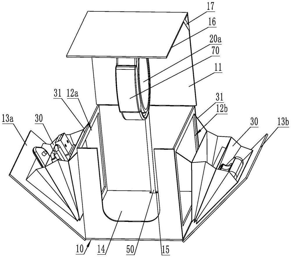
FIG. 2 is a schematic perspective view of an opened electronic product package box according to a first embodiment of the present invention;
FIG. 3 is a schematic perspective view of a linkage mechanism of an electronic product packaging box according to a first embodiment of the present invention;
FIG. 4 is an exploded view of the linkage mechanism of the electronic product packing box according to the first embodiment of the present invention;
FIG. 5 is a schematic drawing showing the stretching principle of the electronic product packing box according to the first embodiment of the present invention;
FIG. 6 is a perspective view of a bracket of the electronic product packing box according to the first embodiment of the present invention;
FIG. 7 is a perspective view of a bracket of an electronic product packing box according to a second embodiment of the present invention;
10, a box body, 11, an upper cover, 12a, a window, 12b, a window, 13a, a side plate, 13b, a side plate, 14, a cover plate, 15, a steering hole, 16, a baffle, 17, a fixing belt, 20a, a support, 20b, a support, 21, a support plate, 22, a ring body, 30, an accessory bag, 31, a pull rope, 41, a slide way, 42a, a driven slide block, 42b, a driven slide block, 43, a driving slide block, 44, a slide plate, 45, a guide groove, 46, an elastic stretching piece, 50, a driving pull belt, 60a, a driven pull belt, 60b, a driven pull belt, 70 and an electronic product.
Detailed Description
In order to make the objects, technical solutions and advantages of the present invention more apparent, the present invention is described in further detail below with reference to the accompanying drawings and embodiments. It should be understood that the specific embodiments described herein are merely illustrative of the invention and are not intended to limit the invention.
Fig. 1 to 7 are schematic structural views of an electronic product packaging box according to an embodiment of the present invention, where fig. 1 illustrates a schematic perspective structural view of the electronic product packaging box according to a first embodiment of the present invention, fig. 2 illustrates a schematic perspective structural view of an opened state of the electronic product packaging box according to the first embodiment of the present invention, fig. 3 illustrates a schematic perspective structural view of a linkage mechanism of the electronic product packaging box according to the first embodiment of the present invention, fig. 4 illustrates an exploded structural view of the linkage mechanism of the electronic product packaging box according to the first embodiment of the present invention, fig. 5 illustrates a schematic drawing principle diagram of the electronic product packaging box according to the first embodiment of the present invention, fig. 6 illustrates a schematic perspective structural view of a bracket of the electronic product packaging box according to the first embodiment of the present invention, and fig. 7 illustrates a schematic perspective structural view of a bracket of the electronic product packaging box according. For the sake of convenience, only the portions related to the embodiments of the present invention are shown in the drawings.
First embodiment
As can be seen from fig. 1 to 6, the electronic product packaging box comprises a box body 10, an upper cover 11 rotatably connected to a side edge of an upper port of the box body 10 for covering the upper port of the box body 10, a window provided on a side wall of the box body 10 at least on one side of a side portion of the upper cover 11, a side plate rotatably connected to the side edge of the window for covering the window, and an accessory bag 30 provided on a side of the side plate close to the window; the box body structure further comprises a linkage mechanism arranged on the inner side wall of one box body 10 between the side walls of the two box bodies 10, a driven pull belt arranged between the linkage mechanism and the side plates, a driving pull belt 50 arranged between the linkage mechanism and the upper cover 11, and an elastic stretching piece 46 arranged on one side of the linkage mechanism far away from the driving pull belt 50, wherein a pull belt steering structure is arranged at a position between the linkage mechanism and the upper cover 11 in the box body 10. Normally, the side walls of the box 10 on both sides are respectively provided with a window 12a and a window 12b, the side edges on the same side of the window 12a and the window 12b are respectively connected with a side plate 13a and a side plate 13b in a rotating manner, the side plates 13a and 13b are respectively provided with an accessory bag 30, a driven pull belt 60a and a driven pull belt 60b are respectively arranged between the linkage mechanism and the side plates 13a and 13b on both sides, and of course, the side walls of the box 10 on only one side can be provided with a window.
Accessories such as a charger, a data line and a specification are respectively placed in the accessory bag 30 on the side plate, and after the electronic product packaging box is closed, the side plate is covered on the window under the pulling of the elastic stretching piece 46, the linkage mechanism and the driven pull belt. Because the driving pull belt 50 is arranged between the upper cover 11 and the linkage mechanism, when the upper cover 11 is opened, the linkage mechanism can be pulled to act through the driving pull belt 50, the elastic stretching piece 46 is stretched at the same time, the pulling force of the driven pull belt on the side plate disappears, and the side plate can be outwards opened from the window, so that the accessories can be conveniently taken from and placed in the accessory bag 30; when the upper cover 11 is closed, the linkage mechanism is driven to perform reverse action under the action of the tensile force of the elastic stretching piece 46, and the side plate is pulled to cover the window through the linkage mechanism and the driven pull belt, so that the whole electronic product packaging box is closed. The electronic product packaging box provided by the embodiment of the invention solves the problem that the existing packaging box is inconvenient to take and place accessories.
In this embodiment, the linkage mechanism includes a driven slider disposed corresponding to the side plate and slidably mounted on the inner side wall of the box 10 along the vertical direction of the window, and a driving slider 43 disposed on a side of the driven slider away from the side plate and slidably mounted on the inner side wall of the box 10 along the vertical direction of the sliding direction of the driven slider, a sliding connection structure is disposed between the driven slider and the corresponding side of the driving slider 43, and an included angle is formed between the arrangement direction of the sliding connection structure and the sliding direction of the driving slider 43; the driven drawstring is connected between the driven slider 42a and the side plate, the driving drawstring 50 is connected between the driving slider 43 and the upper cover 11, and the elastic stretching piece 46 is arranged between one side of the driving slider 43 far away from the driving drawstring 50 and the inner side wall of the box body 10 on the corresponding side.
In the case of providing two windows and two side plates, the linkage mechanism includes a follower slider 42a and a follower slider 42b which are provided corresponding to the side plates 13a and 13b, respectively, and are provided on both sides of the drive slider 43, the follower slider 42a and the follower slider 42b are slidably mounted on the inner side wall of the case 10 in the vertical direction of the window, respectively, a slide coupling structure is provided between the follower slider 42a and 42b and the corresponding side of the drive slider 43, and a follower pull tape 60a and a follower pull tape 60b are connected between the follower slider 42a and 42b and the corresponding side plate 13a and 13b, respectively.
Specifically, the distance between the end of the sliding connection structure close to the side plate and the sliding direction of the driving slider 43 is greater than the distance between the end of the sliding connection structure far from the side plate and the sliding direction of the driving slider 43.
When the upper cover 11 is opened, the upper cover 11 pulls the driving slider 43 to slide through the driving pull belt 50, and simultaneously stretches the elastic stretching piece 46; because the sliding connection structures are respectively arranged between the driven sliding blocks 42a and 42b and the corresponding sides of the driving sliding block 43, and the driven pull belts 60a and 60b are respectively arranged between the driven sliding blocks 42a and 42b and the side plates 13a and 13b on the corresponding sides, when the driving pull belts 50 pull the driving sliding block 43 to slide, the driven sliding blocks 42a and 42b respectively slide towards the direction close to the side plates 13a and 13b under the action of the sliding connection structures, the pulling force acting on the side plates 13a and 13b disappears, and the side plates 13a and 13b can be opened outwards from the windows 12a and 12b on the corresponding sides, so that accessories can be conveniently taken out of and placed in the accessory bag 30; when the upper cover 11 is closed, the driving slider 43 is pulled to slide in the opposite direction under the action of the pulling force of the elastic stretching piece 46, and at the same time, the driven sliders 42a and 42b are driven to slide in the direction away from the side plates 13a and 13b, and the driven pull belts 60a and 60b drive the side plates 13a and 13b to cover the windows 12a and 12b on the corresponding sides, so that the whole electronic product packaging box is closed.
In this embodiment, the side plates 13a and 13b are rotatably connected to the lower side edges of the windows 12a and 12b, respectively, the linkage mechanism is disposed on the bottom side wall of the box 10, the cover plate 14 is disposed on the side of the linkage mechanism away from the bottom side wall of the box 10, a turning hole 15 is disposed at a position of the cover plate 14 close to the rear side wall of the box 10 connected to the upper cover 11, the driving pull belt 50 fixedly connected to the driving slider 43 passes through the turning hole 15 to be connected to the upper cover 11, and the turning hole 15 forms a pull belt turning structure. The linkage mechanism can be hidden in the interlayer formed between the cover plate 14 and the bottom side wall of the box body 10, and the arrangement and the steering of the driving pulling belt 50 are convenient.
In order to facilitate the sliding installation of the driven sliding blocks 42a and 42b, a sliding channel 41 is arranged on the bottom side wall of the box body 10, the driven sliding blocks 42a, 42b and the driving sliding block 43 are all arranged in the sliding channel 41, the widths of the driven sliding blocks 42a and 42b are matched with the width of the sliding channel 41, the driving sliding block 43 can slide between the two sliding channel side walls of the sliding channel 41, notches are respectively arranged on the sliding channel side walls on the two sides of the sliding channel 41 corresponding to the driving sliding block 43, and the driving pull belt 50 and the elastic stretching member 46 respectively penetrate through the notches on the corresponding sides and then are fixedly connected with the driving sliding block 43.
Specifically, the sliding connection structure comprises a guide groove 45 arranged on the driving slider 43 and a sliding plate 44 connected to the driven slider and clamped in the guide groove 45, an included angle is formed between the arrangement direction of the guide groove 45 and the sliding direction of the driving slider 43, and the distance between one end of the guide groove 45 close to the side plate and the sliding direction of the driving slider 43 is larger than the distance between one end of the guide groove 45 far away from the side plate and the sliding direction of the driving slider 43.
In order to reduce the size of the whole linkage mechanism, the side edge setting direction of the driving slider 43 close to the two sides of the driven slider 42a and the driven slider 42b is the same as the setting direction of the corresponding side guide groove 45, and the side edge setting direction of one side of the driven slider 42a and the driven slider 42b close to the driving slider 43 is the same as the side edge setting direction of the corresponding side of the driving slider 43. Thus, the driving slider 43 and the follower slider 42a and the driving slider 43 and the follower slider 42b are in contact with each other at an inclined surface, and the sizes of the driving slider 43, the follower slider 42a, and the follower slider 42b can be reduced.
For ease of understanding, with reference to fig. 5, the distancing of the linkage is illustrated:
in fig. 5, the solid line part indicates the open state of the upper lid 11, and the broken line part indicates the closed state of the upper lid 11; l1 is the distance between the rear side wall of the box body 10 of the upper cover 11 and the turning hole 15 (draw tape turning structure); l2 is the distance between the joint of the driving pulling belt 50 and the upper cover 11 and the joint of the upper cover 11 and the box body 10; x1 is the distance between the turning hole 15 (pull belt turning structure) and the joint of the driving pull belt 50 and the upper cover 11 when the upper cover 11 is in the buckled state; x2 is the distance between the turning hole 15 (pull tape turning structure) and the joint of the driving pull tape 50 and the upper cover 11 when the upper cover 11 is opened. Since X2 is larger than X1, that is, when the upper cover 11 is opened, the upper cover 11 will pull the driving pulling strip 50, so as to pull the driving slider 43 to slide toward one side of the rear side wall of the box body 10 connected to the upper cover 11, and stretch the elastic stretching member 46, since the distance between one end of the sliding connection structure close to the side plate and the sliding direction of the driving slider 43 is larger than the distance between one end of the sliding connection structure far from the side plate and the sliding direction of the driving slider 43, the driven slider 42a and the driven slider 42b respectively slide toward the side plate 13a and the side plate 13b under the action of the sliding connection structure, the pulling force acting on the side plate 13a and the side plate 13b disappears, and the side plate 13a and the side plate 13b will open outwards from the window 12a and the window 12b on the corresponding side.
In order to facilitate the opening of the upper cover 11, the side plates 13a and 13b are opened from the windows 12a and 12b on the corresponding sides, the driven pull tape 60a and 60b include a rigid strip plate portion and a connecting plate portion connected to the end of the strip plate portion, the connecting plate portion and the strip plate portion can rotate relatively along the joint, usually, the driven pull tape 60a and 60b are made of a cardboard or a plastic plate, and the connecting plate portion and the strip plate portion rotate relatively at the joint by providing a crease at a position near the end. Generally, the connecting arm is formed by providing a through hole in the driven slider, and one end of the long plate portion, which is far away from the connecting plate portion, is fixed on the connecting arm, specifically, the end portion of the long plate portion is bent to form a loop on the connecting arm and is bonded by glue, and the connecting plate portion and the side plate are also bonded and fixed.
In this embodiment, a baffle 16 is connected to one side of the upper cover 11 far away from the connection between the upper cover 11 and the box 10, and elastic fixing bands 17 are respectively arranged between the two adjacent sides of the upper cover 11 and the baffle 16, so that after the upper cover 11 is covered on the upper port of the box 10, the fixing bands 17 can block the side plate, and the side plate is ensured to be covered on the window of the corresponding side. When the upper cover 11 and the baffle 16 are in a vertical state, the fixing belt 17 is in a natural state or a stretched state. When the upper cover 11 is closed towards the upper end of the box body 10, the baffle 16 can be rotated towards the outer side, so that the angle between the upper cover 11 and the baffle 16 is larger than 90 degrees, the baffle 16 is prevented from influencing the upper end of the upper cover 11 to close the upper end of the box body 10 due to the angle problem, after the upper cover 11 is closed to the upper end of the box body 10, the baffle 16 can be tightly attached to the side wall of the box body 10 by the fixing band 17, and meanwhile, the baffle can play a role in blocking the side wall, and the accidental opening is prevented.
In this embodiment, a pulling rope 31 is provided between the upper side of the accessory bag 30 and the upper side of the window on the corresponding side, and the pulling rope 31 can play a role of pulling when the side panels 13a and 13b are opened from the window 12a and 12b on the corresponding side.
Specifically, the accessory bag 30 is a foldable bag, and at least two accommodating cavities are formed in the foldable bag, so that accessories can be respectively placed in the accommodating cavities or a plurality of accessories can be respectively placed in one accommodating cavity.
In this embodiment, a bracket 20a for placing an electronic product is fixedly installed on one side of the upper cover 11 near the upper port of the case 10, and the driving pulling tape 50 is fixedly connected to a portion of the upper cover 11 located between the bracket 20a, the connection portion of the upper cover 11 and the case 10. The electronic product is placed on the bracket 20a, and the bracket 20a is fixed on one side of the upper cover 11 close to the upper end of the box 10, so that the bracket 20a can be rotated from the inside of the box 10 to the outside of the box 10 after the upper cover 11 is opened, thereby facilitating the display of the electronic product 70.
Specifically speaking, the support 20a includes the backup pad 21 of being connected with upper cover 11 fixed connection, fixed connection is at the ring body 22 on the backup pad 21, and during the use, directly establish bracelet, intelligent wrist-watch ring cover on the ring body 22 can.
In the present embodiment, the elastic stretching member 46 is a spring, and is disposed between the driving slider 43 and the bottom side wall of the case 10, and usually, a mounting post is disposed on the bottom side wall of the case 10, and an end of the spring is hung on the mounting post.
For the convenience of understanding, the processing and manufacturing of the electronic product packaging box are explained as follows:
generally, the baffle 16 of the electronic product packaging box, the upper cover 11, the rear side wall of the box body 10, the left side wall of the box body 10, the right side wall of the box body 10, and the front side wall of the box body 10 are formed by cutting and folding a piece of paperboard or plastic plate, the side plate 13a, the bottom side wall of the box body 10, and the side plate 13b are also formed by cutting and folding a piece of paperboard or plastic plate, the bottom side wall of the box body 10 and the rear side wall of the box body 10, the left side wall of the box body 10, the right side wall of the box body 10, and the bottom side of the frame enclosed by the front side wall of the box body 10 are bonded or.
Second embodiment
As can be seen from fig. 7, this embodiment is substantially the same as the first embodiment, except that:
support 20b is equipped with including the cover body at the top department of the cover body and places the mouth, can adopt materials such as paper-plastic, plastic uptake to make, with electronic product 70, for example the area body of bracelet, the area body part of intelligent wrist-watch is direct through placing the mouth card in the cavity that the cover body encloses, gets and puts unusual convenience.
The above description is only exemplary of the present invention and should not be taken as limiting the invention, as any modification, equivalent replacement, or improvement made within the spirit and principle of the present invention should be included in the protection scope of the present invention.