CN110948935A - Packaging corrugated carton manufacturing integrated die cutting machine - Google Patents

Packaging corrugated carton manufacturing integrated die cutting machine Download PDF

Info

Publication number
CN110948935A
CN110948935A CN201911345758.8A CN201911345758A CN110948935A CN 110948935 A CN110948935 A CN 110948935A CN 201911345758 A CN201911345758 A CN 201911345758A CN 110948935 A CN110948935 A CN 110948935A
Authority
CN
China
Prior art keywords
die
cutting
indentation
template
bracket
Prior art date
Legal status (The legal status is an assumption and is not a legal conclusion. Google has not performed a legal analysis and makes no representation as to the accuracy of the status listed.)
Granted
Application number
CN201911345758.8A
Other languages
Chinese (zh)
Other versions
CN110948935B (en
Inventor
姚厚君
魏庆
Current Assignee (The listed assignees may be inaccurate. Google has not performed a legal analysis and makes no representation or warranty as to the accuracy of the list.)
Hebei Huazhu Carton Equipment Manufacturing Co ltd
Original Assignee
Individual
Priority date (The priority date is an assumption and is not a legal conclusion. Google has not performed a legal analysis and makes no representation as to the accuracy of the date listed.)
Filing date
Publication date
Application filed by Individual filed Critical Individual
Priority to CN201911345758.8A priority Critical patent/CN110948935B/en
Publication of CN110948935A publication Critical patent/CN110948935A/en
Application granted granted Critical
Publication of CN110948935B publication Critical patent/CN110948935B/en
Active legal-status Critical Current
Anticipated expiration legal-status Critical

Links

Images

Classifications

    • B—PERFORMING OPERATIONS; TRANSPORTING
    • B31—MAKING ARTICLES OF PAPER, CARDBOARD OR MATERIAL WORKED IN A MANNER ANALOGOUS TO PAPER; WORKING PAPER, CARDBOARD OR MATERIAL WORKED IN A MANNER ANALOGOUS TO PAPER
    • B31B—MAKING CONTAINERS OF PAPER, CARDBOARD OR MATERIAL WORKED IN A MANNER ANALOGOUS TO PAPER
    • B31B50/00—Making rigid or semi-rigid containers, e.g. boxes or cartons
    • B31B50/14—Cutting, e.g. perforating, punching, slitting or trimming
    • B31B50/20—Cutting sheets or blanks
    • B—PERFORMING OPERATIONS; TRANSPORTING
    • B31—MAKING ARTICLES OF PAPER, CARDBOARD OR MATERIAL WORKED IN A MANNER ANALOGOUS TO PAPER; WORKING PAPER, CARDBOARD OR MATERIAL WORKED IN A MANNER ANALOGOUS TO PAPER
    • B31B—MAKING CONTAINERS OF PAPER, CARDBOARD OR MATERIAL WORKED IN A MANNER ANALOGOUS TO PAPER
    • B31B50/00—Making rigid or semi-rigid containers, e.g. boxes or cartons
    • B31B50/006—Controlling; Regulating; Measuring; Improving safety
    • B—PERFORMING OPERATIONS; TRANSPORTING
    • B31—MAKING ARTICLES OF PAPER, CARDBOARD OR MATERIAL WORKED IN A MANNER ANALOGOUS TO PAPER; WORKING PAPER, CARDBOARD OR MATERIAL WORKED IN A MANNER ANALOGOUS TO PAPER
    • B31B—MAKING CONTAINERS OF PAPER, CARDBOARD OR MATERIAL WORKED IN A MANNER ANALOGOUS TO PAPER
    • B31B50/00—Making rigid or semi-rigid containers, e.g. boxes or cartons
    • B31B50/25—Surface scoring
    • B31B50/252—Surface scoring using presses or dies
    • B—PERFORMING OPERATIONS; TRANSPORTING
    • B31—MAKING ARTICLES OF PAPER, CARDBOARD OR MATERIAL WORKED IN A MANNER ANALOGOUS TO PAPER; WORKING PAPER, CARDBOARD OR MATERIAL WORKED IN A MANNER ANALOGOUS TO PAPER
    • B31B—MAKING CONTAINERS OF PAPER, CARDBOARD OR MATERIAL WORKED IN A MANNER ANALOGOUS TO PAPER
    • B31B50/00—Making rigid or semi-rigid containers, e.g. boxes or cartons
    • B31B50/74—Auxiliary operations
    • B31B50/92—Delivering
    • B31B50/94—Delivering singly or in succession

Landscapes

  • Making Paper Articles (AREA)

Abstract

本发明涉及一种包装瓦楞纸箱制作整体化模切机械,包括箱体、模床、模切机构、压痕机构与输送机构,箱体底部设置有废料收集箱,箱体中部安装有模床,废料收集箱位于模床正下方,箱体顶端内壁上安装有模切机构和压痕机构,模切机构中间有模切机构,模床位于压痕机构和模切机构正下方,模床前端安装有输送机构。本发明可以解决当下瓦楞纸的加工过程中存在的以下问题:a对瓦楞纸进加工时,对于瓦楞纸模切和压痕两道工序是用模切机器和压痕机器分别进行作业,使得瓦楞纸的加工效率很低;b模床处于模切刀下方,且模切或者压痕好的瓦楞纸需人工将其从模床上取下,这样不仅使得工人存在安全问题,还会增加劳动力。
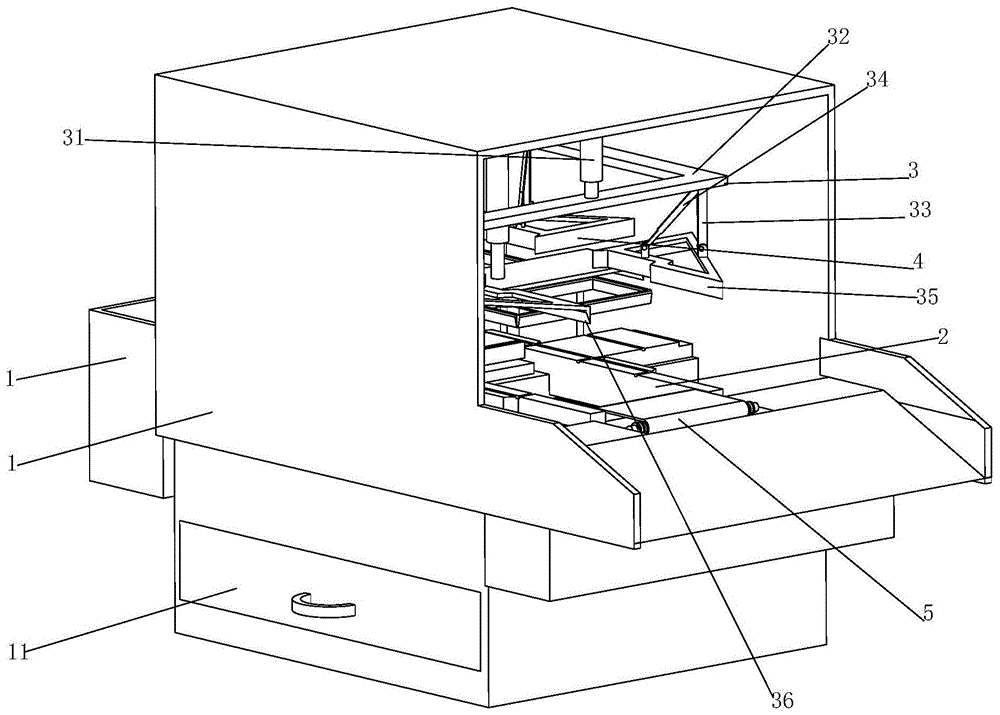
Figure 201911345758

The invention relates to an integrated die-cutting machine for manufacturing corrugated packaging boxes, comprising a box body, a die bed, a die-cutting mechanism, a creasing mechanism and a conveying mechanism. A waste collection box is arranged at the bottom of the box body, and a die bed is arranged in the middle of the box body. The waste collection box is located directly under the die bed. The top inner wall of the box is equipped with a die-cutting mechanism and a creasing mechanism. There is a die-cutting mechanism in the middle of the die-cutting mechanism. The die bed is located directly below the creasing mechanism and the die-cutting mechanism. There is a conveying mechanism. The present invention can solve the following problems existing in the current corrugated paper processing process: a when the corrugated paper is processed, the die-cutting machine and the indentation machine are used for the two processes of corrugated paper die-cutting and indentation, respectively, so that the processing efficiency of the corrugated paper is improved. Very low; the b-die bed is under the die-cutting knife, and the die-cut or indented corrugated paper needs to be manually removed from the die-bed, which not only causes safety problems for workers, but also increases labor.

Figure 201911345758

Description

Packaging corrugated carton manufacturing integrated die cutting machine
Technical Field
The invention relates to the technical field of corrugated paper processing, in particular to an integrated die-cutting machine for manufacturing a packaging corrugated case.
Background
Corrugated paper is a common material for paper packing cases, is lighter than a wood case, has hardness, is easy to cut in size, protects other packaged products from being damaged, is a packaging product with the widest application, and is always the first to use for various packaging products; the corrugated paper board is made into a corrugated paper box through die cutting, indentation, box nailing or box gluing.
The prior corrugated paper processing process also has the following problems: a, when the corrugated paper is processed, a die cutting machine and an indentation machine are respectively used for carrying out operation on the corrugated paper in the two processes of die cutting and indentation, and die cutting is carried out before the die cutting and the indentation or die cutting is carried out after the indentation, so that the processing efficiency of the corrugated paper is very low; b, when the corrugated paper is processed, the corrugated paper needs to be manually placed on a mould bed, the mould bed is just positioned below a mould cutting rule, and the corrugated paper which is subjected to die cutting or has good indentation is manually taken down from the mould bed, so that workers are in danger and the labor force of the workers is increased.
Disclosure of Invention
The invention aims to provide an integrated die-cutting machine for manufacturing a packaging corrugated case, which aims to solve the problems in the background technology.
In order to achieve the purpose, the invention provides the following technical scheme:
an integrated die cutting machine for manufacturing a packaging corrugated carton comprises a box body, a die bed, a die cutting mechanism, an indentation mechanism and a conveying mechanism, wherein a waste collecting box is arranged at the bottom of the box body; wherein:
the die bed comprises a rear seat, a first die plate, a second die plate, a screw rod transmission mechanism and a support frame, wherein the rear seat is installed on the rear side of the box body and connected with the first die plate;
the die cutting mechanism comprises a die cutting cylinder, a rectangular frame, a vertical rod, a hydraulic cylinder, a triangular frame and a die cutting knife, wherein the inner wall of the top of the box body is connected with the bottom end of the die cutting cylinder, the top end of the die cutting cylinder is connected with the upper surface of the rectangular frame, the lower surfaces of four corners of the rectangular frame are connected with the vertical rod and one end of the hydraulic cylinder, the other end of the vertical rod is connected with the middle position of the bevel edge of the triangular frame, the other end of the hydraulic cylinder is connected with the right angle of;
as a further scheme of the invention: the indentation mechanism comprises an indentation cylinder, a rectangular plate, an electric iron and an indentation knife, the inner wall of the top of the box body is connected with the bottom end of the indentation cylinder, the top end of the indentation cylinder is connected with the upper surface of the rectangular plate, the electric iron is uniformly arranged on the lower surface of the rectangular plate, and the indentation knife is arranged below the electric iron;
as a further scheme of the invention: the conveying mechanism comprises a second bracket, a third bracket, a rotating shaft rod, a flywheel, a secondary bevel gear, a front roller, a rear roller and a conveying belt, the second bracket and the third bracket are symmetrically arranged on the left and right of the front end surface of the first template, the second bracket is positioned below the third bracket, the rotating shaft rod is arranged between the second bracket and the third bracket through a bearing, the flywheel is arranged on the middle part of the rotating shaft rod, the secondary bevel gear is arranged on the flywheel and meshed with the primary bevel gear, driving wheels are symmetrically arranged at two ends of the rotating shaft rod, the front roller is arranged between the third bracket, driven wheels are symmetrically arranged at two ends of the front roller, the driving wheels are connected with the driven wheels through belts, the rear roller is arranged on the left and right inner walls at the front end;
as a further scheme of the invention: the screw rod transmission mechanism comprises a motor, a first bracket, a screw rod and a transmission block, the motor is installed at the bottom of the rear seat, the first bracket is respectively installed at the front side and the rear side of the bottom of the first template, the screw rod is installed on the first bracket through a bearing, the output shaft of the motor is connected with one end of the screw rod, the screw rod is connected with the transmission block through thread fit, and a main bevel gear is installed at the other end of the screw rod;
as a further scheme of the invention: the flywheel comprises an inner ring, a shifting sheet, an extension spring and an outer ring, wherein a rotating shaft rod is connected with the inner ring through a bearing, the shifting sheet is arranged on the edge of the inner ring, small holes are formed in the inner ring and the shifting sheet, the extension spring is connected between the small holes, the inner wall of the outer ring is in a sawtooth shape, and the front end of the shifting sheet is clamped between the sawteeth;
as a further scheme of the invention: and the surfaces of the first template and the second template are provided with indentation grooves.
In addition, the invention also provides an integrated die-cutting process for manufacturing the packaging corrugated case, which is mainly completed by matching the integrated die-cutting machine for manufacturing the packaging corrugated case, and comprises the following specific working steps:
manually placing the corrugated paper to be subjected to die cutting and impressing on a rear seat and a second template, starting a motor, and driving a screw rod to rotate by the motor, so that a transmission block drives the second template to move forwards to a proper position and then stop;
secondly, starting a die cutting cylinder to drive a rectangular frame to move downwards, driving a vertical rod to move downwards by the rectangular frame so as to drive a triangular frame to move downwards until a die cutting knife cuts the corrugated paper, then informing the die cutting cylinder, starting a hydraulic cylinder, pushing the right angle of the triangular frame to move downwards, and performing cutting action on the corrugated paper;
thirdly, simultaneously electrifying the electric soldering iron to heat the indentation knife, driving the rectangular plate to move downwards by the indentation cylinder until the corrugated paper is pressed into the indentation groove by the indentation knife, stopping the indentation cylinder, withdrawing the die cutting mechanism and the indentation mechanism after the corrugated paper is subjected to die cutting and indentation, starting the motor to rotate reversely, and recovering the second template;
fourthly, simultaneously, the main bevel gear drives the auxiliary bevel gear to rotate so as to drive the flywheel to rotate, the flywheel drives the rotating shaft rod to rotate, the rotating shaft rod drives the driving wheel to rotate, the driving wheel drives the driven wheel to rotate through a belt, so that the front roller and the rear roller are driven to rotate, and the conveying belt conveys the corrugated paper with the die-cut indentations into the collecting box from the die bed; and finishing the die cutting indentation work of the corrugated paper.
Compared with the prior art, the invention has the following advantages:
the following problems existing in the processing process of corrugated paper can be solved: a, when the corrugated paper is processed, a die cutting machine and an indentation machine are respectively used for carrying out operation on the corrugated paper in the two processes of die cutting and indentation, and die cutting is carried out before the die cutting and the indentation or die cutting is carried out after the indentation, so that the processing efficiency of the corrugated paper is very low; b, when the corrugated paper is processed, the corrugated paper needs to be manually placed on a mould bed, the mould bed is just below a mould cutting rule, and the corrugated paper which is subjected to die cutting or indentation is manually taken down from the mould bed, so that workers are in danger and the labor force of the workers is increased;
when the die cutting mechanism and the indentation mechanism of the device work, the corrugated paper can be simultaneously subjected to die cutting and indentation, so that the die cutting process and the indentation process of the original corrugated paper are combined into one, the working time is saved, and the efficiency of corrugated paper processing is increased; when the device is used for the die bed, the second template can slide on the first template, so that corrugated paper can be placed on the second template only by manpower, the motor can be started to drive the corrugated paper to move to the position below the die cutting mechanism for die cutting, and workers are prevented from being directly positioned below the die cutting mechanism.
Drawings
The invention is further illustrated with reference to the following figures and examples.
FIG. 1 is a schematic perspective view of the present invention;
FIG. 2 is a schematic elevational cross-sectional plan view of the present invention;
FIG. 3 is a side cross-sectional plan view of the present invention;
FIG. 4 is an enlarged plan view of the invention at A in FIG. 2;
FIG. 5 is a schematic cross-sectional plan view of the flywheel of the present invention;
Detailed Description
In order to make the technical means, the creation features, the achievement purposes and the effects of the invention easy to understand, the invention is further explained with reference to fig. 1 to 5.
The utility model provides a packing corrugated box preparation integration cross cutting machinery, includes box 1, mould bed 2, die-cutting mechanism 3, indentation mechanism 4 and conveying mechanism 5, its characterized in that: the waste collecting box 11 is arranged at the bottom of the box body 1, the die bed 2 is arranged in the middle of the box body 1, the waste collecting box 11 is positioned under the die bed 2, the die cutting mechanism 3 and the indentation mechanism 4 are arranged on the inner wall of the top of the box body 1, the die cutting mechanism 3 is arranged in the middle of the die cutting mechanism 3, the die bed 2 is positioned under the indentation mechanism 4 and the die cutting mechanism 3, and the conveying mechanism 5 is arranged at the front end of the die bed 2; wherein:
the die bed 2 comprises a rear seat 21, a first die plate 22, a second die plate 23, a screw rod transmission mechanism 24 and a support frame 25, the rear seat 21 is installed on the rear side of the box body 1, the rear seat 21 is connected with the first die plate 22, a slide way 221 is formed in the first die plate 22 from front to back, a rectangular slide block 222 is installed in the slide way 221 in a sliding mode, a limit groove 223 is formed in the upper surface of the rectangular slide block 222, the bottom of the limit groove 223 is connected with one end of a buffer spring 224, the other end of the buffer spring 224 is connected with the bottom surface of the second die plate 23, a baffle 231 is arranged at the rear end of the second die plate 23, a rectangular hole 225 is formed in the bottom surface of the slide way 221, the screw rod transmission mechanism 24 is installed at the bottom of the first die plate 22;
during specific work, screw drive mechanism 24 drives rectangle slider 222 and removes in slide 221, rectangle slider 222 drives No. two templates 23 to suitable position after, alright carry out the cross cutting indentation to the corrugated paper, during the indentation, indentation mechanism 4 can be pushed down No. two templates 23 to agreeing horizontal position with template 22, buffer spring 224 can slow down the impact force that indentation mechanism 4 brought, can also make indentation mechanism 4 laminate more with template 22 and No. two templates 23, the indentation effect of corrugated paper can be better like this.
The die-cutting mechanism 3 comprises a die-cutting cylinder 31, a rectangular frame 32, a vertical rod 33, a hydraulic cylinder 34, a triangular frame 35 and a die-cutting knife 36, the inner wall of the top of the box body 1 is connected with the bottom end of the die-cutting cylinder 31, the top end of the die-cutting cylinder 31 is connected with the upper surface of the rectangular frame 32, the lower surfaces of four corners of the rectangular frame 32 are connected with the vertical rod 33 and one end of the hydraulic cylinder 34, the other end of the vertical rod 33 is connected with the middle position of the bevel edge of the triangular frame 35, the other end of the hydraulic cylinder 34 is connected with the right angle;
when the corrugated paper cutting machine works specifically, the die cutting cylinder 31 drives the rectangular frame 32 to move downwards, the rectangular frame 32 drives the vertical rod 33 to move downwards so as to drive the triangular frame 35 to move downwards until the die cutting knife 36 cuts the corrugated paper, then the die cutting cylinder 31 is informed, the hydraulic cylinder 34 is started, the right angle of the triangular frame 35 is pushed to move downwards, the corrugated paper is cut, after the corrugated paper is cut, the hydraulic cylinder 34 drives the triangular frame 35 to restore to the horizontal position, then the die cutting cylinder 31 moves upwards to the initial position, and one-time die cutting of the corrugated paper is finished.
The creasing mechanism 4 comprises a creasing cylinder 41, a rectangular plate 42, an electric soldering iron 43 and a creasing knife 44, the inner wall of the top of the box body 1 is connected with the bottom end of the creasing cylinder 41, the top end of the creasing cylinder 41 is connected with the upper surface of the rectangular plate 42, the electric soldering iron 43 is uniformly installed on the lower surface of the rectangular plate 42, the creasing knife 44 is installed below the electric soldering iron 43, during specific work, the electric soldering iron 43 is electrified to heat the creasing knife 44, then the creasing cylinder 41 drives the rectangular plate 42 to move downwards until the creasing knife 44 presses the corrugated paper into a creasing groove 221, then the creasing cylinder 41 is stopped, after the die cutting mechanism 3 completes the die cutting of the corrugated paper, the creasing cylinder 41 is started at the same time, the electric soldering iron 43 is closed, the creasing mechanism 4 is recovered to the initial position, once corrugated paper is finished, the electric soldering iron.
The conveying mechanism 5 comprises a second bracket 51, a third bracket 52, a rotating shaft rod 53, flywheels 54, a secondary bevel gear 55, a front roller 56, a rear roller 57 and a conveying belt 58, the second bracket 51 and the third bracket 52 are symmetrically installed on the left and right of the front end surface of the first template 22, the second bracket 51 is positioned below the third bracket 52, the rotating shaft rod 53 is installed between the second bracket 51 through a bearing, the flywheel 54 is installed on the middle part of the rotating shaft rod 53, the secondary bevel gear 55 is installed on the flywheels 54, the secondary bevel gear 55 is meshed with the primary bevel gear 245, driving wheels 531 are symmetrically installed at two ends of the rotating shaft rod 53, the front roller 56 is installed between the third brackets 52, driven wheels 561 are symmetrically installed at two ends of the front roller 56, the driving wheels 531 are connected with the driven wheels 561 through belts 562, the rear rollers 57 are installed on the left and right inner walls of the front end of the;
when the corrugated paper die-cutting indentation machine works specifically, after the die-cutting indentation of the corrugated paper is finished, the screw rod transmission mechanism 24 drives the second template 23 to move forwards under the action of the flywheel 54, the conveying mechanism 5 cannot rotate along with the screw rod transmission mechanism 24, and when the screw rod transmission mechanism 24 drives the second template 23 to move backwards, the conveying mechanism 5 rotates along with the screw rod transmission mechanism; the main bevel gear 245 drives the secondary bevel gear 55 to rotate so as to drive the flywheel 54 to rotate, the flywheel 54 drives the rotating shaft rod 53 to rotate, the rotating shaft rod 53 drives the driving wheel 531 to rotate, the driving wheel 531 drives the driven wheel 561 to rotate through the belt 562 so as to drive the front roller 56 and the rear roller 57 to rotate, and the conveying belt 58 is used for conveying the corrugated paper with the die-cutting indentations to the collecting box from the die bed 2.
The screw rod transmission mechanism 24 comprises a motor 241, a first bracket 242, a screw rod 243 and a transmission block 244, the motor 241 is installed at the bottom of the rear seat 21, the first bracket 242 is installed at the front side and the rear side of the bottom of the first template 22 respectively, the screw rod 243 is installed on the first bracket 242 through a bearing, the output shaft of the motor 241 is connected with one end of the screw rod 243, the screw rod 243 is connected with the transmission block 244 in a threaded fit manner, and the main bevel gear 245 is installed at the other end of the screw rod 243; during specific work, the motor 241 drives the screw rod 243 to rotate, so that the transmission block 244 drives the second template 23 to move back and forth, and the screw rod 243 drives the main bevel gear 245 to rotate, so that the conveying mechanism 5 is driven to rotate.
The flywheel 54 comprises an inner ring 541, a shifting piece 542, an extension spring 543 and an outer ring 544, the rotating shaft rod 53 is connected with the inner ring 541 through a bearing, the shifting piece 542 is mounted on the edge of the inner ring 541, small holes are formed in the inner ring 541 and the shifting piece 542, the extension spring 543 is connected between the small holes, the inner wall of the outer ring 544 is in a sawtooth shape, and the front end of the shifting piece 542 is clamped between the sawteeth; during specific work, the outer ring 544 rotates along with the slave bevel gear 55, when the slave bevel gear 55 rotates forwards, the plectrum 542 is shifted between sawteeth, the outer ring 544 cannot be clamped, therefore, the inner ring 541 cannot rotate, when the slave bevel gear 55 rotates backwards, the front end of the plectrum 542 can be clamped with the outer ring 544, and therefore the inner ring 541 rotates along with the rotation, and the transmission mechanism 5 is driven to rotate.
Indentation grooves 221 are formed in the surfaces of the first template 22 and the second template 23, and the indentation grooves 221 enable the corrugated paper to be more accurate in indentation position and better in indentation effect.
In addition, the invention also provides an integrated die-cutting process for manufacturing the packaging corrugated case, which is mainly completed by matching the integrated die-cutting machine for manufacturing the packaging corrugated case, and comprises the following specific working steps:
fifthly, manually placing the corrugated paper to be subjected to die cutting and impressing on the rear seat 21 and the second template 23, starting the motor 241, and driving the screw rod 243 to rotate by the motor 241, so that the transmission block 244 drives the second template 23 to move forwards to a proper position and then stop;
sixthly, starting the die cutting cylinder 31 to drive the rectangular frame 32 to move downwards, driving the vertical rod 33 to move downwards by the rectangular frame 32 so as to drive the triangular frame 35 to move downwards until the die cutting rule 36 cuts the corrugated paper, then informing the die cutting cylinder 31, starting the hydraulic cylinder 34 to push the right angle of the triangular frame 35 to move downwards, and performing cutting action on the corrugated paper;
seventhly, simultaneously electrifying the electric soldering iron 43 to heat the indentation knife 44, driving the rectangular plate 42 to move downwards by the indentation cylinder 41 until the indentation knife 44 presses the corrugated paper into the indentation groove 221, then stopping the indentation cylinder 41, withdrawing the die cutting mechanism 3 and the indentation mechanism 4 after the corrugated paper is subjected to die cutting and indentation, starting the motor 241 to rotate reversely, and recovering the second template 23;
eighthly, simultaneously, the main bevel gear 245 drives the secondary bevel gear 55 to rotate so as to drive the flywheel 54 to rotate, the flywheel 54 drives the rotating shaft rod 53 to rotate, the rotating shaft rod 53 drives the driving wheel 531 to rotate, the driving wheel 531 drives the driven wheel 561 to rotate through the belt 562 so as to drive the front roller 56 and the rear roller 57 to rotate, and the conveying belt 58 is enabled to convey the corrugated paper with the die-cutting indentations to the collecting box from the die bed 2; and finishing the die cutting indentation work of the corrugated paper.
Although the preferred embodiments of the present patent have been described in detail, the present patent is not limited to the above embodiments, and various changes can be made without departing from the spirit of the present patent within the knowledge of those skilled in the art.

Claims (6)

1.一种包装瓦楞纸箱制作整体化模切机械,包括箱体(1)、模床(2)、模切机构(3)、压痕机构(4)与输送机构(5),其特征在于:箱体(1)底部设置有废料收集箱(11),箱体(1)中部安装有模床(2),废料收集箱(11)位于模床(2)正下方,箱体(1)顶部内壁上安装有模切机构(3)和压痕机构(4),模切机构(3)中间有模切机构(3),模床(2)位于压痕机构(4)和模切机构(3)正下方,模床(2)前端安装有输送机构(5);其中:1. An integrated die-cutting machine for packaging corrugated carton production, comprising a box body (1), a die bed (2), a die-cutting mechanism (3), an indentation mechanism (4) and a conveying mechanism (5), characterized in that : A waste collection box (11) is arranged at the bottom of the box body (1), a mold bed (2) is installed in the middle of the box body (1), and the waste collection box (11) is located directly below the mold bed (2). The box body (1) A die-cutting mechanism (3) and a creasing mechanism (4) are installed on the inner wall of the top, and a die-cutting mechanism (3) is located in the middle of the die-cutting mechanism (3), and the die bed (2) is located between the creasing mechanism (4) and the die-cutting mechanism. (3) Directly below, a conveying mechanism (5) is installed at the front end of the die bed (2); wherein: 所述模床(2)包括后座(21)、一号模板(22)、二号模板(23)、丝杆传动机构(24)与支撑架(25),箱体(1)后侧安装有后座(21),后座(21)与一号模板(22)连接,一号模板(22)从前往后开设有滑道(221),滑道(221)内滑动安装矩形滑块(222),矩形滑块(222)上表面开设有限位槽(223),限位槽(223)底部与缓冲弹簧(224)一端连接,缓冲弹簧(224)另一端与二号模板(23)底面连接,二号模板(23)后端设置有挡板(231),滑道(221)底面开设有矩形孔(225),一号模板(22)底部安装有丝杆传动机构(24),二号模板(23)下表面与支撑架(25)连接,支撑架(25)下表面与丝杆传动机构(24)连接;The mold bed (2) includes a back seat (21), a No. 1 template (22), a No. 2 template (23), a screw drive mechanism (24) and a support frame (25), and the box body (1) is installed on the rear side There is a back seat (21), the back seat (21) is connected with the No. 1 template (22), and the No. 1 template (22) is provided with a slideway (221) from front to back, and a rectangular slider (221) is slidably installed in the slideway (221). 222), a limit slot (223) is provided on the upper surface of the rectangular slider (222), the bottom of the limit slot (223) is connected with one end of the buffer spring (224), and the other end of the buffer spring (224) is connected with the bottom surface of the second template (23). Connection, the rear end of the second template (23) is provided with a baffle (231), the bottom surface of the slideway (221) is provided with a rectangular hole (225), the bottom of the first template (22) is installed with a screw drive mechanism (24), the second The lower surface of the template (23) is connected with the support frame (25), and the lower surface of the support frame (25) is connected with the screw drive mechanism (24); 所述模切机构(3)包括模切气缸(31)、矩形框(32)、竖杆(33)、液压缸(34)、三角形框(35)与模切刀(36),箱体(1)顶部内壁与模切气缸(31)底端连接,模切气缸(31)顶端与矩形框(32)上表面连接,矩形框(32)四个角的下表面均与竖杆(33)和液压缸(34)的一端连接,竖杆(33)另一端与三角形框(35)的斜边中间位置连接,液压缸(34)另一端与三角形框(35)直角处连接,三角形框(35)下表面均匀安装有模切刀(36)。The die-cutting mechanism (3) includes a die-cutting cylinder (31), a rectangular frame (32), a vertical rod (33), a hydraulic cylinder (34), a triangular frame (35) and a die-cutting knife (36), and a box body ( 1) The top inner wall is connected to the bottom end of the die-cutting cylinder (31), the top of the die-cutting cylinder (31) is connected to the upper surface of the rectangular frame (32), and the lower surfaces of the four corners of the rectangular frame (32) are connected to the vertical rod (33) It is connected to one end of the hydraulic cylinder (34), the other end of the vertical rod (33) is connected to the middle position of the hypotenuse of the triangular frame (35), and the other end of the hydraulic cylinder (34) is connected to the right angle of the triangular frame (35). 35) A die-cutting knife (36) is evenly installed on the lower surface. 2.根据权利要求1所述的一种包装瓦楞纸箱制作整体化模切机械,其特征在于:所述压痕机构(4)包括压痕气缸(41)、矩形板(42)、电烙铁(43)与压痕刀(44),箱体(1)顶部内壁与压痕气缸(41)底端连接,压痕气缸(41)顶端与矩形板(42)上表面连接,矩形板(42)下表面均匀安装有电烙铁(43),电烙铁(43)下方安装有压痕刀(44)。2. The integrated die-cutting machine for manufacturing corrugated boxes according to claim 1, characterized in that: the indentation mechanism (4) comprises an indentation cylinder (41), a rectangular plate (42), an electric soldering iron (4). 43) Connect with the indentation knife (44), the top inner wall of the box (1) and the bottom end of the indentation cylinder (41), the top of the indentation cylinder (41) is connected with the upper surface of the rectangular plate (42), and the rectangular plate (42) An electric soldering iron (43) is evenly installed on the lower surface, and an indentation knife (44) is installed under the electric soldering iron (43). 3.根据权利要求1所述的一种包装瓦楞纸箱制作整体化模切机械,其特征在于:所述输送机构(5)包括二号支架(51)、三号支架(52)、转轴杆(53)、飞轮(54)、从锥齿轮(55)、前辊(56)、后辊(57)与传送带(58),一号模板(22)前端面左右对称安装有二号支架(51)和三号支架(52),二号支架(51)位于三号支架(52)下方,二号支架(51)之间通过轴承安装有转轴杆(53),转轴杆(53)中部上安装有飞轮(54),飞轮(54)上安装有从锥齿轮(55),从锥齿轮(55)与主锥齿轮(245)啮合,转轴杆(53)两端对称安装有主动轮(531),三号支架(52)之间安装有前辊(56),前辊(56)两端对称安装有从动轮(561),主动轮(531)与从动轮(561)通过皮带(562)连接,后辊(57)安装在滑道(221)前端左右内壁上,前辊(56)与后辊(57)之间通过传送带(58)连接。3. The integrated die-cutting machine for making packaging corrugated boxes according to claim 1, wherein the conveying mechanism (5) comprises a No. 2 bracket (51), a No. 3 bracket (52), a rotating shaft (5). 53), the flywheel (54), the follower bevel gear (55), the front roller (56), the rear roller (57) and the conveyor belt (58), the front end surface of the No. 1 template (22) is symmetrically installed with a No. 2 bracket (51) and the No. 3 bracket (52), the No. 2 bracket (51) is located below the No. 3 bracket (52), a rotating shaft rod (53) is installed between the No. 2 brackets (51) through bearings, and a rotating shaft rod (53) is installed in the middle The flywheel (54) has a slave bevel gear (55) installed on the flywheel (54), the slave bevel gear (55) meshes with the main bevel gear (245), and a driving wheel (531) is installed symmetrically at both ends of the rotating shaft (53), A front roller (56) is installed between the No. 3 brackets (52), and driven wheels (561) are installed symmetrically at both ends of the front roller (56). The rear rollers (57) are installed on the left and right inner walls of the front end of the slideway (221), and the front rollers (56) and the rear rollers (57) are connected by a conveyor belt (58). 4.根据权利要求1所述的一种包装瓦楞纸箱制作整体化模切机械,其特征在于:所述丝杆传动机构(24)包括电机(241)、一号支架(242)、丝杆(243)与传动块(244),后座(21)底部安装有电机(241),一号模板(22)底部前后侧各安装有一号支架(242),一号支架(242)上通过轴承安装丝杆(243),电机(241)输出轴与丝杆(243)一端连接,丝杆(243)与传动块(244)通过螺纹配合连接,丝杆(243)另一端安装有主锥齿轮(245)。4. The integrated die-cutting machine for manufacturing corrugated boxes according to claim 1, wherein the screw drive mechanism (24) comprises a motor (241), a No. 1 bracket (242), a screw (24) 243) and the transmission block (244), a motor (241) is installed at the bottom of the rear seat (21), a No. 1 bracket (242) is installed on the front and rear sides of the bottom of the No. 1 template (22), and the No. 1 bracket (242) is installed by bearings The lead screw (243), the output shaft of the motor (241) is connected with one end of the lead screw (243), the lead screw (243) and the transmission block (244) are connected by threaded fitting, and the other end of the lead screw (243) is installed with a main bevel gear ( 245). 5.根据权利要求3所述的一种包装瓦楞纸箱制作整体化模切机械,其特征在于:所述飞轮(54)包括内圈(541)、拨片(542)、拉伸弹簧(543)与外圈(544),转轴杆(53)通过轴承与内圈(541)连接,内圈(541)边上安装有拨片(542),内圈(541)和拨片(542)上均开设有小孔,小孔之间连接有拉伸弹簧(543),外圈(544)内壁呈锯齿状,拨片(542)前端卡在锯齿之间。5. The integrated die-cutting machine for manufacturing corrugated packaging boxes according to claim 3, wherein the flywheel (54) comprises an inner ring (541), a pick (542), and a tension spring (543) With the outer ring (544), the shaft rod (53) is connected with the inner ring (541) through bearings, and a paddle (542) is installed on the edge of the inner ring (541), and both the inner ring (541) and the paddle (542) are Small holes are opened, tension springs (543) are connected between the small holes, the inner wall of the outer ring (544) is serrated, and the front end of the paddle (542) is clamped between the serrations. 6.根据权利要求1所述的一种包装瓦楞纸箱制作整体化模切机械,其特征在于:所述一号模板(22)与二号模板(23)表面均开设有压痕槽(221)。6. The integrated die-cutting machine for making a packaging corrugated carton according to claim 1, wherein an indentation groove (221) is provided on the surfaces of the No. 1 template (22) and the No. 2 template (23) .
CN201911345758.8A 2019-12-24 2019-12-24 An integrated die-cutting machine for making packaging corrugated boxes Active CN110948935B (en)

Priority Applications (1)

Application Number Priority Date Filing Date Title
CN201911345758.8A CN110948935B (en) 2019-12-24 2019-12-24 An integrated die-cutting machine for making packaging corrugated boxes

Applications Claiming Priority (1)

Application Number Priority Date Filing Date Title
CN201911345758.8A CN110948935B (en) 2019-12-24 2019-12-24 An integrated die-cutting machine for making packaging corrugated boxes

Publications (2)

Publication Number Publication Date
CN110948935A true CN110948935A (en) 2020-04-03
CN110948935B CN110948935B (en) 2021-05-11

Family

ID=69983918

Family Applications (1)

Application Number Title Priority Date Filing Date
CN201911345758.8A Active CN110948935B (en) 2019-12-24 2019-12-24 An integrated die-cutting machine for making packaging corrugated boxes

Country Status (1)

Country Link
CN (1) CN110948935B (en)

Cited By (4)

* Cited by examiner, † Cited by third party
Publication number Priority date Publication date Assignee Title
CN112644073A (en) * 2020-11-18 2021-04-13 江西华利包装科技有限责任公司 Cutting and processing equipment for hard packaging carton
CN114889208A (en) * 2022-05-25 2022-08-12 合肥祥恒包装有限公司 Production and processing equipment for high-strength corrugated paper packaging box
CN114952997A (en) * 2021-09-06 2022-08-30 童缨 Preparation method of PP packaging box
CN118596256A (en) * 2024-05-21 2024-09-06 山东润平塑业有限公司 A skeleton box automatic production device and production process

Citations (14)

* Cited by examiner, † Cited by third party
Publication number Priority date Publication date Assignee Title
DE2615042A1 (en) * 1976-04-07 1977-10-20 Heinz Amberg Corrugated blank folding device - consisting of table with four base supports and forming box with movable pressure lever
CN2815682Y (en) * 2005-07-15 2006-09-13 孔宪银 Reciprocating flat-impress die cutting machine
WO2010102510A1 (en) * 2009-03-09 2010-09-16 瑞安市奥尔印刷包装机械有限公司 Fully automatic platen press type creasing and cutting machine
CN201659715U (en) * 2009-08-07 2010-12-01 苏州市正宝塑料制品有限公司 Automatic double-side gluing machine
CN105172203A (en) * 2015-07-28 2015-12-23 湖州旺翔纸业包装有限公司 Creasing device capable of adjusting paperboard depth for small paper boxes
CN204976828U (en) * 2015-08-05 2016-01-20 领胜电子科技(成都)有限公司 Cross cutting machine of wasting discharge
CN107584804A (en) * 2017-09-13 2018-01-16 深圳劲嘉集团股份有限公司 A kind of laser die cutting corrugated case Full automatic packaging mechanism and its method
CN207954785U (en) * 2018-01-19 2018-10-12 莆田市燎原包装印刷有限公司 A kind of carton die cutting machine easy to use
CN108724311A (en) * 2018-07-15 2018-11-02 福州通立工业设计有限公司 A kind of film hole punched device producing packaging bag
CN208164388U (en) * 2018-02-28 2018-11-30 嘉兴市鸿业包装有限公司 A kind of carton die cutting impression integrated device
CN109015894A (en) * 2018-10-23 2018-12-18 江门市厚润纸制品有限公司 A kind of die-cutting machine facilitating stripping
CN208730443U (en) * 2018-08-24 2019-04-12 安吉集隆包装材料有限公司 A kind of corrugated board laminated yarn slotting die-cutting device
CN110039823A (en) * 2019-05-08 2019-07-23 宛群 A kind of Packaging Box die-cutting process and its die-cutting machine
CN209775684U (en) * 2019-04-12 2019-12-13 北京棋淼工贸有限公司 Cross cutting machine convenient to unloading in automation

Patent Citations (14)

* Cited by examiner, † Cited by third party
Publication number Priority date Publication date Assignee Title
DE2615042A1 (en) * 1976-04-07 1977-10-20 Heinz Amberg Corrugated blank folding device - consisting of table with four base supports and forming box with movable pressure lever
CN2815682Y (en) * 2005-07-15 2006-09-13 孔宪银 Reciprocating flat-impress die cutting machine
WO2010102510A1 (en) * 2009-03-09 2010-09-16 瑞安市奥尔印刷包装机械有限公司 Fully automatic platen press type creasing and cutting machine
CN201659715U (en) * 2009-08-07 2010-12-01 苏州市正宝塑料制品有限公司 Automatic double-side gluing machine
CN105172203A (en) * 2015-07-28 2015-12-23 湖州旺翔纸业包装有限公司 Creasing device capable of adjusting paperboard depth for small paper boxes
CN204976828U (en) * 2015-08-05 2016-01-20 领胜电子科技(成都)有限公司 Cross cutting machine of wasting discharge
CN107584804A (en) * 2017-09-13 2018-01-16 深圳劲嘉集团股份有限公司 A kind of laser die cutting corrugated case Full automatic packaging mechanism and its method
CN207954785U (en) * 2018-01-19 2018-10-12 莆田市燎原包装印刷有限公司 A kind of carton die cutting machine easy to use
CN208164388U (en) * 2018-02-28 2018-11-30 嘉兴市鸿业包装有限公司 A kind of carton die cutting impression integrated device
CN108724311A (en) * 2018-07-15 2018-11-02 福州通立工业设计有限公司 A kind of film hole punched device producing packaging bag
CN208730443U (en) * 2018-08-24 2019-04-12 安吉集隆包装材料有限公司 A kind of corrugated board laminated yarn slotting die-cutting device
CN109015894A (en) * 2018-10-23 2018-12-18 江门市厚润纸制品有限公司 A kind of die-cutting machine facilitating stripping
CN209775684U (en) * 2019-04-12 2019-12-13 北京棋淼工贸有限公司 Cross cutting machine convenient to unloading in automation
CN110039823A (en) * 2019-05-08 2019-07-23 宛群 A kind of Packaging Box die-cutting process and its die-cutting machine

Cited By (5)

* Cited by examiner, † Cited by third party
Publication number Priority date Publication date Assignee Title
CN112644073A (en) * 2020-11-18 2021-04-13 江西华利包装科技有限责任公司 Cutting and processing equipment for hard packaging carton
CN114952997A (en) * 2021-09-06 2022-08-30 童缨 Preparation method of PP packaging box
CN114889208A (en) * 2022-05-25 2022-08-12 合肥祥恒包装有限公司 Production and processing equipment for high-strength corrugated paper packaging box
CN114889208B (en) * 2022-05-25 2023-12-19 合肥祥恒包装有限公司 Production and processing equipment for high-strength corrugated paper packaging box
CN118596256A (en) * 2024-05-21 2024-09-06 山东润平塑业有限公司 A skeleton box automatic production device and production process

Also Published As

Publication number Publication date
CN110948935B (en) 2021-05-11

Similar Documents

Publication Publication Date Title
CN110948935B (en) An integrated die-cutting machine for making packaging corrugated boxes
CN101774183B (en) Full-automatic thick material rubber cutting method and rubber cutting machine for implementing same
CN204414652U (en) Non-woven fabric solid shape bag forming machine
CN206633090U (en) A kind of impression cutting machine of automatic loading/unloading
CN110588070A (en) Intelligent processing method of packaging carton
CN205767701U (en) A kind of cardboard automatic slotting machine
CN107457820A (en) A kind of multifunctional sponge slicing machine
CN108608048B (en) Plate shearing machine
CN215943824U (en) Die-cutting machine for carton packaging production
CN205818030U (en) The two-way guillotine of EVA
CN214821236U (en) Cardboard cutting device for production and processing of packaging boxes
CN223904624U (en) A cardboard die-cutting device for packaging box processing
CN206751050U (en) A kind of packing machine wound membrane splits continous way cutting mechanism automatically
CN211278774U (en) Bamboo one-time knife, fork and spoon integrated forming machine
CN212168690U (en) Plate cutting device for producing iron packaging box
CN221022814U (en) Paper packing carton fixing device
CN220332102U (en) Paper packing box perforating device
CN217968601U (en) A cardboard cutting device for carton production
CN214394466U (en) A flat creasing and cutting machine for removing edge material
CN215750329U (en) High-efficient positive negative pressure plastic uptake shaping of full automatization cuts all-in-one
CN106003243A (en) EVA bidirectional cutting machine
CN221292456U (en) Trimming device for packaging paper box
CN214238602U (en) A combined die-cutting equipment
CN221892124U (en) A flat creasing and cutting machine for fireworks processing
CN219988583U (en) Die cutting machine with fixed knot constructs

Legal Events

Date Code Title Description
PB01 Publication
PB01 Publication
SE01 Entry into force of request for substantive examination
TA01 Transfer of patent application right

Effective date of registration: 20210420

Address after: 311200 Zhongli village, Yinong Town, Xiaoshan District, Hangzhou City, Zhejiang Province (No. 73)

Applicant after: Hangzhou Caihong Packaging Co.,Ltd.

Address before: Tibet Institute of agriculture and animal husbandry, 100 Yucai West Road, Bayi District, Linzhi City, Tibet 860000

Applicant before: Yao Houjun

TA01 Transfer of patent application right
GR01 Patent grant
GR01 Patent grant
TR01 Transfer of patent right

Effective date of registration: 20220311

Address after: 311300 No. 129, xinxiqiao village, Jincheng Street, Lin'an District, Hangzhou City, Zhejiang Province

Patentee after: Hangzhou Lin'an Wanda printing and packaging Co.,Ltd.

Address before: 311200 Zhongli village, Yinong Town, Xiaoshan District, Hangzhou City, Zhejiang Province (No. 73)

Patentee before: Hangzhou Caihong Packaging Co.,Ltd.

TR01 Transfer of patent right

Effective date of registration: 20250109

Address after: Room 313, No. 52, East Side of Yangcui Road, Dayanchang Town, Wuqing District, Tianjin City, 301706

Patentee after: Tianjin Qinyi Information Technology Co.,Ltd.

Country or region after: China

Address before: 311300 No. 129, xinxiqiao village, Jincheng Street, Lin'an District, Hangzhou City, Zhejiang Province

Patentee before: Hangzhou Lin'an Wanda printing and packaging Co.,Ltd.

Country or region before: China

TR01 Transfer of patent right

Effective date of registration: 20250313

Address after: 061000 South Xiazhuang Village, Dongguang Town, Dongguang County, Cangzhou City, Hebei Province (east side of National Highway 105)

Patentee after: Hebei Huazhu Carton Equipment Manufacturing Co.,Ltd.

Country or region after: China

Address before: Room 313, No. 52, East Side of Yangcui Road, Dayanchang Town, Wuqing District, Tianjin City, 301706

Patentee before: Tianjin Qinyi Information Technology Co.,Ltd.

Country or region before: China

TR01 Transfer of patent right