CN110948698A - Special feeding device for lime-soil mixing - Google Patents
Special feeding device for lime-soil mixing Download PDFInfo
- Publication number
- CN110948698A CN110948698A CN201911348199.6A CN201911348199A CN110948698A CN 110948698 A CN110948698 A CN 110948698A CN 201911348199 A CN201911348199 A CN 201911348199A CN 110948698 A CN110948698 A CN 110948698A
- Authority
- CN
- China
- Prior art keywords
- stirring
- soil
- lime
- hoop
- conveying
- Prior art date
- Legal status (The legal status is an assumption and is not a legal conclusion. Google has not performed a legal analysis and makes no representation as to the accuracy of the status listed.)
- Pending
Links
Images



Classifications
-
- B—PERFORMING OPERATIONS; TRANSPORTING
- B28—WORKING CEMENT, CLAY, OR STONE
- B28C—PREPARING CLAY; PRODUCING MIXTURES CONTAINING CLAY OR CEMENTITIOUS MATERIAL, e.g. PLASTER
- B28C7/00—Controlling the operation of apparatus for producing mixtures of clay or cement with other substances; Supplying or proportioning the ingredients for mixing clay or cement with other substances; Discharging the mixture
- B28C7/04—Supplying or proportioning the ingredients
- B28C7/06—Supplying the solid ingredients, e.g. by means of endless conveyors or jigging conveyors
-
- B—PERFORMING OPERATIONS; TRANSPORTING
- B28—WORKING CEMENT, CLAY, OR STONE
- B28C—PREPARING CLAY; PRODUCING MIXTURES CONTAINING CLAY OR CEMENTITIOUS MATERIAL, e.g. PLASTER
- B28C7/00—Controlling the operation of apparatus for producing mixtures of clay or cement with other substances; Supplying or proportioning the ingredients for mixing clay or cement with other substances; Discharging the mixture
- B28C7/0007—Pretreatment of the ingredients, e.g. by heating, sorting, grading, drying, disintegrating; Preventing generation of dust
-
- B—PERFORMING OPERATIONS; TRANSPORTING
- B28—WORKING CEMENT, CLAY, OR STONE
- B28C—PREPARING CLAY; PRODUCING MIXTURES CONTAINING CLAY OR CEMENTITIOUS MATERIAL, e.g. PLASTER
- B28C7/00—Controlling the operation of apparatus for producing mixtures of clay or cement with other substances; Supplying or proportioning the ingredients for mixing clay or cement with other substances; Discharging the mixture
- B28C7/04—Supplying or proportioning the ingredients
- B28C7/0422—Weighing predetermined amounts of ingredients, e.g. for consecutive delivery
- B28C7/0431—Weighing predetermined amounts of ingredients, e.g. for consecutive delivery using a weighing belt or the like
Landscapes
- Chemical & Material Sciences (AREA)
- Dispersion Chemistry (AREA)
- Consolidation Of Soil By Introduction Of Solidifying Substances Into Soil (AREA)
- Mixers Of The Rotary Stirring Type (AREA)
Abstract
The invention discloses a special loading device for mixing lime and soil, which belongs to the technical field of building construction equipment and comprises a plurality of discharging bins arranged on a rack in parallel, wherein the inlet of each discharging bin is provided with a screening mechanism for loosening soil materials, and the bottom of each discharging bin is provided with a stirring mechanism for secondarily loosening the soil materials in the discharging bin; and a metering conveying mechanism for metering and conveying soil materials is arranged below the outlet of the discharging bin. The soil material is loosened in advance through the screening mechanism arranged at the inlet of the discharging bin, so that the blockage and accumulation at the feeding hole are avoided, the loosened soil material is loosened for the second time at the bottom of the discharging bin through the stirring mechanism, and the influence of arching of the soil material in the discharging bin on discharging is avoided; and the soil falling from the outlet of the blanking bin falls to a metering conveying mechanism for metering and conveying to a mixing station for mixing. The invention can make the soil material fall smoothly, can effectively improve the batching speed and ensure the accurate measurement of the soil material.
Description
Technical Field
The invention belongs to the technical field of building construction equipment, and particularly relates to a special feeding device for mixing lime soil.
Background
The construction quality of the high-speed railway subgrade directly influences the operation safety of the high-speed railway, and the high-speed railway subgrade has high design standard, high construction difficulty and particularly high construction quality. In the prior art, a high-speed railway foundation has the following requirements on improved soil filling construction: 1. sieving the soil; 2. soil quality needs to be concentrated and stirred in a field (stirring in a stirring station); 3 soil should have a soil breaking device (breaking soil). At present, a stabilized soil mixing station is usually selected for mixing in actual construction. However, the following problems arise during the actual modified soil mixing process:
1. the upper opening screen of the feeding hopper is easy to block and pile, and the feeding is not smooth; 2. after the soil material enters the hopper, because the hopper is in a structure form of inverted cone, the upper opening is large, the lower opening is small, and when a large amount of rapid soil material passes through, crowding and connection blocks are generated at the middle lower part to form an arched soil layer, so that the material cannot be discharged or the material can be discharged intermittently, the subsequent passage of the soil material is influenced, and the material mixing capacity is influenced; 3. the soil material metering is inaccurate due to intermittent feeding or impact feeding caused by falling of large lumps; 4. the actual efficacy is very low.
Disclosure of Invention
The technical problem to be solved by the invention is to provide a special feeding device for mixing lime soil, which can enable soil to fall smoothly, effectively improve the batching speed and ensure accurate soil metering.
In order to solve the technical problems, the technical scheme adopted by the invention is as follows:
a special feeding device for lime-soil mixing comprises a plurality of discharging bins arranged on a rack in parallel, wherein a screening mechanism for loosening soil materials is arranged at the inlet of each discharging bin, and a stirring mechanism for secondarily loosening the soil materials in each discharging bin is arranged at the bottom of each discharging bin; and a metering conveying mechanism for metering and conveying soil materials is arranged below the outlet of the discharging bin.
Preferably, the screening mechanism comprises a vibrator and a screen, and the vibrator is connected with the screen; the screen cloth is horizontally erected at the upper open end of the lower storage bin through a spring support.
Preferably, the spring support comprises a support seat, a guide sleeve, a spring and a guide column, the longitudinal section of the support seat is 7-shaped, two ends of the support seat are fixed on the inner wall of the lower storage bin, and the upper surface of the support seat is horizontally arranged; the guide sleeve is arranged on the upper surface of the support seat, the guide column is arranged on the lower surface of the screen, and the guide column is in sliding fit with an inner hole of the guide sleeve; the spring is sleeved outside the guide sleeve, the upper end of the spring is fixedly connected with the screen, and the lower end of the spring is fixedly connected with the supporting seat.
Preferably, the stirring mechanism comprises two stirring shafts which rotate reversely and are driven by a stirring motor, and the two stirring shafts are arranged at the bottom of the blanking bin at intervals in parallel; a plurality of stirring arms are radially arranged on the outer circle of the stirring shaft along the length direction of the stirring shaft, and the stirring arms on the two stirring shafts are arranged in a staggered manner; the stirring motor and the two stirring shafts are arranged on the frame.
Preferably, the stirring arm is L-shaped, the long side part of the stirring arm is provided with a radian, the short side part of the stirring arm is provided with an arch breaking blade, the arch breaking blades of the stirring arm on the same stirring shaft face the same direction, and the arch breaking blades of the stirring arm on the other stirring shaft are arranged in the opposite direction.
Preferably, the long edge part of the stirring arm is arranged on the fixing sleeve, the fixing sleeve is of a split structure and comprises a first hoop and a second hoop, one end of the first hoop is pivoted with one end of the second hoop, and the other end of the first hoop is movably connected with the other end of the second hoop and is used for fixing the first hoop and the second hoop on the excircle of the stirring shaft; the stirring arm is fixedly arranged on the outer surface of the first hoop or the second hoop, and the arc grooves of the first hoop and the second hoop are matched with the stirring shaft.
Furthermore, two stirring shafts penetrate through the lower parts of the plurality of blanking bins, the stirring motor is arranged at one end of each stirring shaft, and the other end of each stirring shaft is arranged on the bearing seat; the number of the stirring motors is one or two, and the stirring motors drive the two stirring shafts to rotate through the transmission assembly.
Preferably, the lower bin is a hollow cavity with a large upper opening and a small lower opening, the cross section of the lower bin is rectangular, and the inclination angles α of the long sides of the two sides of the lower bin are 63 degrees and 64 degrees.
Preferably, measurement conveying mechanism includes a plurality of belt weigher and conveyer, and a plurality of belt weigher corresponds the export below that sets up in feed bin under a plurality of, conveyer sets up in the below of a plurality of belt weigher for carry the soil material to the station of mixing of one side.
Preferably, the belt weigher comprises a conveying motor, a speed reducer, a driving roller, a driven roller and a conveying belt, an output shaft of the conveying motor is coaxially fixed with an input shaft of the speed reducer, an output shaft of the speed reducer is coaxially fixed with a rotating shaft of the driving roller, the conveying belt is connected with the driving roller and the driven roller, and a rubber layer is wrapped on the excircle of the driving roller.
Adopt the produced beneficial effect of above-mentioned technical scheme to lie in: compared with the prior art, the invention loosens the soil material in advance through the screening mechanism arranged at the inlet of the discharging bin, avoids the blockage and accumulation at the feeding port, loosens the loosened soil material for the second time at the bottom of the discharging bin through the stirring mechanism, and avoids the influence of the arching of the soil material in the discharging bin on the discharging; and the soil falling from the outlet of the blanking bin falls to a metering conveying mechanism for metering and conveying to a mixing station for mixing. The invention can make the soil material fall smoothly, can effectively improve the batching speed and ensure the accurate measurement of the soil material.
Drawings
FIG. 1 is a schematic structural diagram of a special loading device for lime soil mixing according to an embodiment of the present invention;
FIG. 2 is a right side view of FIG. 1;
FIG. 3 is a top view of the screen of FIG. 2;
FIG. 4 is a schematic view of the connection of the screen and the blanking bin of FIG. 1;
FIG. 5 is an enlarged view of a portion of FIG. 1 at A;
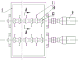
FIG. 6 is a top view of an agitation mechanism in an embodiment of the present invention;
FIG. 7 is a sectional view A-A of FIG. 6;
in the figure: 1-a frame; 2-discharging the material bin; 3-a vibrator; 4-screening the screen; 5-a support seat; 6, a guide sleeve; 7-a spring; 8-a guide post; 9-a stirring motor; 10-a stirring shaft; 11-stirring arm, 110-arch breaking blade; 12-a fixing sleeve, 120-a first hoop, 121-a second hoop; 13-belt scale, 131-conveying motor, 132-speed reducer, 133-driving roller, 134-conveying belt, 135-driven roller, 136-transmission roller shaft and 137-skirt edge; 14-a conveyor belt; 15-an operating platform; 15-guardrail.
Detailed Description
In order to make the objects, technical solutions and advantages of the present invention more apparent, the present invention will be described in further detail with reference to the accompanying drawings and specific embodiments. It should be understood that the specific embodiments described herein are merely illustrative of the invention and are not intended to limit the invention.
As shown in fig. 1, the special feeding device for mixing the ash and the soil, provided by the embodiment of the invention, comprises a plurality of discharging bins 2 arranged on a rack 1 in parallel, wherein an inlet of each discharging bin 2 is provided with a screening mechanism for loosening the soil, and the bottom of each discharging bin 2 is provided with a stirring mechanism for secondarily loosening the soil in each discharging bin 2; and a metering conveying mechanism for metering and conveying soil materials is arranged below an outlet of the discharging bin 2.
Compared with the prior art, the special loading device for mixing the lime and the soil has the advantages of simple and compact structure and high working efficiency, soil is loosened and sieved in advance through the sieving mechanism, the blockage and accumulation at the feed inlet of the discharging bin are avoided, then the soil in the discharging bin is loosened for the second time through the stirring mechanism at the bottom, the arching phenomenon of the soil at the discharge outlet is avoided, and finally the fallen soil falls to the metering conveying mechanism to be metered and conveyed to the mixing station for mixing. The invention can make the soil material fall smoothly, can effectively improve the batching speed and ensure the accurate measurement of the soil material.
In a preferred embodiment of the present invention, as shown in fig. 1-3, the screening mechanism comprises a vibrator 3 and a screen 4, the vibrator 3 is connected with the screen 4; the screen 4 is horizontally erected at the upper open end of the lower storage bin 2 through a spring support. In view of the large screen mesh number of the feeding port of the blanking bin and the small soil penetration rate, in the process of unloading soil at the position of the bucket of the loader, soil falls and impacts, so that soil bodies are mutually extruded and piled into a cluster, the cluster is gradually enlarged, and most of the screen is blocked. Therefore, the grid screen is fixed at the inlet of the discharging bin through the spring support, the screen is excited by the vibrator, and the phenomena that the soil body drops and is extruded into a cluster and piled into a sheet when passing through the screen are relieved.
In one embodiment of the present invention, as shown in fig. 4, the spring support includes a support seat 5, a guide sleeve 6, a spring 7 and a guide post 8, a longitudinal section of the support seat 5 is "7", two ends of the support seat 5 are fixed on an inner wall of the lower bin 2, and an upper surface of the support seat 5 is horizontally disposed; the guide sleeve 6 is arranged on the upper surface of the support seat 5, the guide column 8 is arranged on the lower surface of the screen 4, and the guide column 8 is in sliding fit with an inner hole of the guide sleeve 6; the spring 7 is sleeved outside the guide sleeve 6, the upper end of the spring 7 is fixedly connected with the screen 4, and the lower end of the spring 7 is fixedly connected with the supporting seat 5. The method comprises the following steps of manufacturing a rectangular vibration framework by utilizing channel steel, welding and fixing a screen on the framework, welding and fixing guide pillars on the lower surfaces of four corners of the framework, and installing a vibrator above the framework to drive a grid screen to vibrate up and down at high frequency, so that soil mass agglomeration is avoided, and the soil mass is dispersed and easily passes through the screen; the grid sieve material is formed by vertically welding a flat iron group instead of original deformed steel bars, and is favorable for soil falling.
Further optimize above-mentioned technical scheme, upper portion sets up an attached vibrator in the outer wall of feed bin down, prevents that the soil material from bonding on the inner wall of feed bin down, influences the trafficability characteristic of feed bin under of soil material.
In a preferred embodiment of the present invention, as shown in fig. 6 and 7, the stirring mechanism comprises two stirring shafts 10 rotating in opposite directions and driven by a stirring motor 9, and the two stirring shafts 10 are arranged at the bottom of the lower bin 2 in parallel at intervals; a plurality of stirring arms 11 are radially arranged on the outer circle of the stirring shaft 10 along the length direction of the outer circle, and the stirring arms 11 on the two stirring shafts 10 are arranged in a staggered manner; the stirring motor 9 and the two stirring shafts 10 are both arranged on the frame 1. Because the structural style of the blanking bin is the inverted cone, the upper opening is large, the lower opening is small, and when a large amount of rapid soil passes through, crowding and caking can be generated at the middle lower part to form an arched soil layer, so that the passing of subsequent soil is influenced, and the batching capacity is influenced. The two stirring shafts are driven to rotate by the stirring motor, and the falling soil materials are forcibly conveyed downwards by the stirring arms, so that the soil materials are prevented from arching and blocking.
As a preferable scheme, as shown in fig. 6 and 7, the stirring arm 11 is designed to be L-shaped, the long side portion of the stirring arm 11 has a radian, the short side portion of the stirring arm is an arch breaking blade 110, the arch breaking blades 110 of the stirring arm 11 on the same stirring shaft 10 face the same direction, and the arch breaking blades 110 of the stirring arm 11 on the other stirring shaft 10 are arranged in the opposite direction. The arch breaking blade with the structure can effectively cut, break soil and break arch of soil materials, and forcibly and continuously stir and forcibly convey the soil materials downwards through the double horizontal shafts.
The two stirring shafts 10 penetrate through the lower parts of the plurality of lower bins 2, the stirring motor 9 is arranged at one end of each stirring shaft 10, and the other end of each stirring shaft 10 is arranged on the bearing block; the number of the stirring motors 9 is one or two, and the stirring motors 9 drive the two stirring shafts 10 to rotate through the transmission assembly. The rotating directions of the two stirring shafts are opposite, so loose soil materials can be effectively stirred.
During the specific design, two 7.5kw stirring motor reducers are arranged at the middle lower part of the discharging bin to drive the stirring shaft and the stirring arm to rotate, so that the soil is continuously stirred, and the soil is forcibly cut, broken and arched, and has the function of forcibly conveying the soil downwards. In the work, start agitator motor, it is rotatory to drive horizontal double-mixing shaft through speed reducer, shaft coupling, and biax reverse rotation drives the rabbling arm and stirs the blade rotation, stirs, cuts the soil material, has not only broken and has encircleed the soil body of loosing but also the compulsory downward stirring carries the soil material, makes the soil material fall to measurement, output belt feeder through the feed opening fast downwards on, improves the whereabouts trafficability ability of soil material in the hopper, and then has improved the productivity effect of batching.
Further optimizing the above technical solution, as shown in fig. 7, the long side portion of the stirring arm 11 is disposed on the fixing sleeve 12, the fixing sleeve 12 is of a split structure, the fixing sleeve 12 includes a first anchor ear 120 and a second anchor ear 121, one end of the first anchor ear 120 is pivoted with one end of the second anchor ear 121, and the other end of the first anchor ear 120 is movably connected with the other end of the second anchor ear 121, so as to fix the first anchor ear 120 and the second anchor ear 121 on the outer circle of the stirring shaft 10; the stirring arm 11 is fixedly arranged on the outer surface of the first hoop 120 or the second hoop 121, and the arc grooves of the first hoop 120 and the second hoop 121 are matched with the stirring shaft 10. Adopt this structure to make things convenient for the stirring arm installation to dismantle, easy maintenance is swift.
In a specific embodiment of the present invention, as shown in fig. 2, the lower bin 2 is a hollow cavity with a large opening at the top and a small opening at the bottom, the cross section of the lower bin 2 is rectangular, and the inclination angles α of the long sides at the two sides of the lower bin 2 are 63 ° and 64 °, when the manufacturing is specifically performed, the size of the discharge port of the lower bin can be increased, that is, the discharge port is changed from 730mm 650mm to 1400mm 730mm, the inclination angles of the steel plates of the long sides at the two sides are changed from 51 ° and 64 ° to 63 ° and 64 °, meanwhile, the volume of the lower bin is increased from 10m to 11m, the passing area of the discharge port of the lower bin is changed from 0.4745m2 to 1.022m2, the passing area is increased by more than one time, and the passing capacity is greatly improved.
In an embodiment of the invention, as shown in fig. 1, 2 and 5, the metering and conveying mechanism includes a plurality of belt scales 13 and a conveyor belt 14, the plurality of belt scales 13 are correspondingly disposed below the outlets of the plurality of blanking bins 2, and the conveyor belt 14 is disposed below the plurality of belt scales 13 and is used for conveying the soil material to a mixing station on one side. The belt scale 13 includes a conveying motor 131, a speed reducer 132, a driving roller 133, a driven roller 135 and a conveying belt 134, an output shaft of the conveying motor 131 is coaxially fixed with an input shaft of the speed reducer 132, an output shaft of the speed reducer 132 is coaxially fixed with a rotating shaft of the driving roller 133, the conveying belt 134 is connected with the driving roller 133 and the driven roller 135, and a rubber layer is wrapped on an outer circle of the driving roller 133. Conveying motor, speed reducer, initiative cylinder and driven cylinder all set up on the support frame, and the top of support frame is equipped with a plurality of and is used for bearing the driving roll axle 136 of conveyer belt, and the both sides edge of conveyer belt is equipped with shirt rim 137. Because the discharge gate length of feed bin is to the size by original 730mm change 1400mm down, and the width is to changing into 730mm by original 650mm, makes the unloading soil volume increase by a wide margin after the feed opening increase, and original belt weigher conveying capacity is obviously not enough. The motor power and mechanism of a belt transmission roller of the original belt scale are changed from a 4kw power electric roller to a 7.5kw external transmission motor reducer, so that the transmission capacity of the belt scale is improved; a rubber layer is added on the surface layer of the outer circle of the driving roller, so that the friction force between the surface of the driving roller and the conveying belt is increased, and the phenomenon that the conveying belt stops due to overload or the main transmission roller slips from the conveying belt is prevented; the width of the conveying belt for metering and conveying materials is correspondingly widened due to the increase of the width of the feed opening; therefore, the soil material metering capacity is increased, the precision is improved, the stability is better, and the service life is prolonged.
In a specific embodiment of the present invention, as shown in fig. 2, a protective plate 15 extending upward is disposed around the opening at the upper end of the lower silo 2 to prevent the soil from spilling out of the lower silo during the loading process; the side of lower feed bin 2 is equipped with operation platform 16, operation platform 16's edge is equipped with guardrail 17, makes things convenient for the staff to install and maintain.
The invention is used for batching and metering soil and other aggregates, and the upper grid screen basically has no accumulated soil; the internal soil material of the discharging bin passes through the discharging bin smoothly without accumulation, vault and soil conglomeration; the belt weigher has accurate measurement and stable operation. The production capacity of aggregate batching is increased to 350T/h from the original 100T/h, the capacity is improved by 3.5 times, the batching capacity is effectively improved, and the blending quality can meet the requirement of high-speed rail improved soil roadbed construction. The invention can be used in parallel with the original water stabilizing station proportioning machine, and can also be used in a matched way with the water stabilizing station main machine to form a whole set of lime soil mixing station. Has the following advantages:
1. a feeding port of the blanking bin is not easy to block and accumulate, the aggregate passing performance is good, and the efficiency is high;
2. the middle part of the discharging bin is not easy to agglomerate and arch, and has the functions of forced stirring, crushing and forced material conveying, thereby greatly improving the forced passing capacity of the aggregate and greatly passing the production capacity;
3. after the size of a discharging opening of the discharging bin is increased, the bucket wall can discharge materials quickly, and the discharging capacity is greatly improved;
4. the discharge metering capacity is increased, the precision is improved, and the service life of the belt is prolonged;
5. the requirement on the performance index of the aggregate can be reduced, and the adaptability is greatly improved;
6. high specialization degree, safe and reliable performance and high efficiency.
The principles and embodiments of the present invention are explained herein using specific examples, which are presented only to assist in understanding the method and its core concepts. It should be noted that, for those skilled in the art, it is possible to make various improvements and modifications to the present invention without departing from the principle of the present invention, and those improvements and modifications also fall within the scope of the claims of the present invention.
Claims (10)
Priority Applications (1)
| Application Number | Priority Date | Filing Date | Title |
|---|---|---|---|
| CN201911348199.6A CN110948698A (en) | 2019-12-24 | 2019-12-24 | Special feeding device for lime-soil mixing |
Applications Claiming Priority (1)
| Application Number | Priority Date | Filing Date | Title |
|---|---|---|---|
| CN201911348199.6A CN110948698A (en) | 2019-12-24 | 2019-12-24 | Special feeding device for lime-soil mixing |
Publications (1)
| Publication Number | Publication Date |
|---|---|
| CN110948698A true CN110948698A (en) | 2020-04-03 |
Family
ID=69983841
Family Applications (1)
| Application Number | Title | Priority Date | Filing Date |
|---|---|---|---|
| CN201911348199.6A Pending CN110948698A (en) | 2019-12-24 | 2019-12-24 | Special feeding device for lime-soil mixing |
Country Status (1)
| Country | Link |
|---|---|
| CN (1) | CN110948698A (en) |
Cited By (3)
| Publication number | Priority date | Publication date | Assignee | Title |
|---|---|---|---|---|
| CN111497009A (en) * | 2020-05-29 | 2020-08-07 | 常州机电职业技术学院 | Dust free dust mixer |
| CN117001849A (en) * | 2023-05-26 | 2023-11-07 | 徐州徐工养护机械有限公司 | A kind of stabilized soil mixing equipment special for phosphogypsum sticky materials |
| CN120592241A (en) * | 2025-06-03 | 2025-09-05 | 成都建工第八建筑工程有限公司 | A fertilizer trough backfilling method, a grouting pipe and a mixing device |
Citations (8)
| Publication number | Priority date | Publication date | Assignee | Title |
|---|---|---|---|---|
| JP2006336355A (en) * | 2005-06-03 | 2006-12-14 | Kirikawa Bussan:Kk | Equipment for crushing and stirring construction residue |
| CN102152400A (en) * | 2011-01-28 | 2011-08-17 | 葛洲坝集团试验检测有限公司 | Continuous mixing system for preparing impervious soil and control method |
| CN202192022U (en) * | 2011-07-27 | 2012-04-18 | 北新集团建材股份有限公司 | A lower hopper capable of shaking off raw materials and a silo containing the hopper |
| CN204038255U (en) * | 2014-07-28 | 2014-12-24 | 胡海伟 | A kind of integral type broken arch feeder |
| CN104264567A (en) * | 2014-10-16 | 2015-01-07 | 中铁三局集团有限公司 | Forced stirring and crushing machine for bituminous mixture |
| CN206569745U (en) * | 2017-02-25 | 2017-10-20 | 天津合嘉宏建混凝土有限公司 | A kind of sandstone blanking device |
| CN208526376U (en) * | 2018-07-10 | 2019-02-22 | 山东传诚环保科技有限公司 | A kind of Horizontal type stirring device |
| CN211440601U (en) * | 2019-12-24 | 2020-09-08 | 中铁三局集团第二工程有限公司 | Special feeding device for lime-soil mixing |
-
2019
- 2019-12-24 CN CN201911348199.6A patent/CN110948698A/en active Pending
Patent Citations (8)
| Publication number | Priority date | Publication date | Assignee | Title |
|---|---|---|---|---|
| JP2006336355A (en) * | 2005-06-03 | 2006-12-14 | Kirikawa Bussan:Kk | Equipment for crushing and stirring construction residue |
| CN102152400A (en) * | 2011-01-28 | 2011-08-17 | 葛洲坝集团试验检测有限公司 | Continuous mixing system for preparing impervious soil and control method |
| CN202192022U (en) * | 2011-07-27 | 2012-04-18 | 北新集团建材股份有限公司 | A lower hopper capable of shaking off raw materials and a silo containing the hopper |
| CN204038255U (en) * | 2014-07-28 | 2014-12-24 | 胡海伟 | A kind of integral type broken arch feeder |
| CN104264567A (en) * | 2014-10-16 | 2015-01-07 | 中铁三局集团有限公司 | Forced stirring and crushing machine for bituminous mixture |
| CN206569745U (en) * | 2017-02-25 | 2017-10-20 | 天津合嘉宏建混凝土有限公司 | A kind of sandstone blanking device |
| CN208526376U (en) * | 2018-07-10 | 2019-02-22 | 山东传诚环保科技有限公司 | A kind of Horizontal type stirring device |
| CN211440601U (en) * | 2019-12-24 | 2020-09-08 | 中铁三局集团第二工程有限公司 | Special feeding device for lime-soil mixing |
Non-Patent Citations (2)
| Title |
|---|
| 暴纯武: "《草原生产机械化》", 31 May 1993, 农业出版社, pages: 126 - 127 * |
| 陈学英: "《烧结配料工》", 31 October 2014, 冶金工业出版社, pages: 107 * |
Cited By (3)
| Publication number | Priority date | Publication date | Assignee | Title |
|---|---|---|---|---|
| CN111497009A (en) * | 2020-05-29 | 2020-08-07 | 常州机电职业技术学院 | Dust free dust mixer |
| CN117001849A (en) * | 2023-05-26 | 2023-11-07 | 徐州徐工养护机械有限公司 | A kind of stabilized soil mixing equipment special for phosphogypsum sticky materials |
| CN120592241A (en) * | 2025-06-03 | 2025-09-05 | 成都建工第八建筑工程有限公司 | A fertilizer trough backfilling method, a grouting pipe and a mixing device |
Similar Documents
| Publication | Publication Date | Title |
|---|---|---|
| CN203781279U (en) | Raw material batching system | |
| CN107855206A (en) | A kind of sub- disintegrating equipment of construction sand | |
| CN209905948U (en) | A feeder suitable for high viscosity full tailings | |
| AU2021102861A4 (en) | Special feeding device for cement and soil mixing | |
| CN215038827U (en) | Concrete feeding device | |
| CN214082127U (en) | Mixer convenient to material loading | |
| CN211440601U (en) | Special feeding device for lime-soil mixing | |
| CN202921545U (en) | Premixing and self-cleaning roller type screening device | |
| CN216104606U (en) | Feeding device and feeding system | |
| CN214925689U (en) | Homogenizing device for producing low-alkali cement by using industrial waste residues | |
| CN114100432B (en) | Gravity type single vertical shaft stirrer | |
| CN213005907U (en) | Fine powder raw material batching hopper for continuous stirring station | |
| CN116872363A (en) | A direct-injection fluid self-compacting solidified soil production equipment | |
| CN214605172U (en) | Complete equipment for preparing liquefied consolidated soil from waste residue soil | |
| CN209954997U (en) | Mixed stirring and packaging system for UHPC material | |
| CN211566380U (en) | High-speed stirring device for inorganic mixture | |
| CN224118344U (en) | Uniform discharging device for cement production | |
| CN218230270U (en) | Anti-blocking type stock bin to be granulated | |
| CN218111210U (en) | A agitating unit for engineering road is laid | |
| CN218944950U (en) | Biological fertilizer raw materials reducing mechanism | |
| CN218857329U (en) | A multifunctional concrete batching and mixing device | |
| CN205009390U (en) | Incline a little to mixing from formula earth material that falls and mix device | |
| CN220075128U (en) | Mobilizable concrete mixing plant | |
| CN214637215U (en) | Cement clinker raw materials for production handles and uses jaw crusher loading attachment | |
| CN218875870U (en) | Concrete dosing unit is used in environmental protection concrete production |
Legal Events
| Date | Code | Title | Description |
|---|---|---|---|
| PB01 | Publication | ||
| PB01 | Publication | ||
| SE01 | Entry into force of request for substantive examination | ||
| SE01 | Entry into force of request for substantive examination | ||
| RJ01 | Rejection of invention patent application after publication |
Application publication date: 20200403 |
|
| RJ01 | Rejection of invention patent application after publication |