CN110917754A - Efficient automatic bag-type dust removal washing device and washing and drying method - Google Patents
Efficient automatic bag-type dust removal washing device and washing and drying method Download PDFInfo
- Publication number
- CN110917754A CN110917754A CN201911358629.2A CN201911358629A CN110917754A CN 110917754 A CN110917754 A CN 110917754A CN 201911358629 A CN201911358629 A CN 201911358629A CN 110917754 A CN110917754 A CN 110917754A
- Authority
- CN
- China
- Prior art keywords
- washing
- drying
- dust removal
- cloth bag
- control system
- Prior art date
- Legal status (The legal status is an assumption and is not a legal conclusion. Google has not performed a legal analysis and makes no representation as to the accuracy of the status listed.)
- Pending
Links
Images



Classifications
-
- B—PERFORMING OPERATIONS; TRANSPORTING
- B01—PHYSICAL OR CHEMICAL PROCESSES OR APPARATUS IN GENERAL
- B01D—SEPARATION
- B01D46/00—Filters or filtering processes specially modified for separating dispersed particles from gases or vapours
- B01D46/02—Particle separators, e.g. dust precipitators, having hollow filters made of flexible material
- B01D46/023—Pockets filters, i.e. multiple bag filters mounted on a common frame
-
- B—PERFORMING OPERATIONS; TRANSPORTING
- B01—PHYSICAL OR CHEMICAL PROCESSES OR APPARATUS IN GENERAL
- B01D—SEPARATION
- B01D46/00—Filters or filtering processes specially modified for separating dispersed particles from gases or vapours
- B01D46/02—Particle separators, e.g. dust precipitators, having hollow filters made of flexible material
- B01D46/04—Cleaning filters
-
- B—PERFORMING OPERATIONS; TRANSPORTING
- B01—PHYSICAL OR CHEMICAL PROCESSES OR APPARATUS IN GENERAL
- B01D—SEPARATION
- B01D46/00—Filters or filtering processes specially modified for separating dispersed particles from gases or vapours
- B01D46/66—Regeneration of the filtering material or filter elements inside the filter
- B01D46/70—Regeneration of the filtering material or filter elements inside the filter by acting counter-currently on the filtering surface, e.g. by flushing on the non-cake side of the filter
- B01D46/71—Regeneration of the filtering material or filter elements inside the filter by acting counter-currently on the filtering surface, e.g. by flushing on the non-cake side of the filter with pressurised gas, e.g. pulsed air
-
- B—PERFORMING OPERATIONS; TRANSPORTING
- B01—PHYSICAL OR CHEMICAL PROCESSES OR APPARATUS IN GENERAL
- B01D—SEPARATION
- B01D46/00—Filters or filtering processes specially modified for separating dispersed particles from gases or vapours
- B01D46/66—Regeneration of the filtering material or filter elements inside the filter
- B01D46/70—Regeneration of the filtering material or filter elements inside the filter by acting counter-currently on the filtering surface, e.g. by flushing on the non-cake side of the filter
- B01D46/72—Regeneration of the filtering material or filter elements inside the filter by acting counter-currently on the filtering surface, e.g. by flushing on the non-cake side of the filter with backwash arms, shoes or nozzles
-
- F—MECHANICAL ENGINEERING; LIGHTING; HEATING; WEAPONS; BLASTING
- F26—DRYING
- F26B—DRYING SOLID MATERIALS OR OBJECTS BY REMOVING LIQUID THEREFROM
- F26B21/00—Arrangements for supplying or controlling air or other gases for drying solid materials or objects
- F26B21/001—Air generating units, e.g. movable or independent of drying enclosure
Landscapes
- Chemical & Material Sciences (AREA)
- Chemical Kinetics & Catalysis (AREA)
- Engineering & Computer Science (AREA)
- Mechanical Engineering (AREA)
- General Engineering & Computer Science (AREA)
- Cleaning In General (AREA)
Abstract
The invention belongs to a high-efficiency automatic washing device for bag dust removal and a washing and drying method; the automatic walking washing and drying device comprises a cloth bag dust removal box, wherein a plurality of dust removal cloth bags in the cloth bag dust removal box are divided into a plurality of rows and arranged at the upper part in the cloth bag dust removal box, and a group of automatic walking washing and drying units are correspondingly arranged at the bottom of each row of dust removal cloth bags; the automatic walking washing and drying unit comprises a horizontal walking part, a vertical walking part and a washing and drying part; a washing nozzle in the washing drying part is connected with a first tee joint through a hose with a control valve, and the second end of the first tee joint is connected with a cloth bag washing water tank through a water pipe stop valve and an automatic washing water pump in sequence; the third end of the first tee joint is connected with a water return port of the cloth bag flushing water tank through a second tee joint and a flushing water return valve, and the third end of the second tee joint is connected with an air drying fan through an air pipe cut-off valve and the shell pass of the air heat exchanger; the bag-type dust collector has the advantages of being stable in operation, prolonging the service life of the bag in the bag-type dust collector and avoiding the influence on the normal operation of equipment caused by the replacement of the bag.
Description
Technical Field
The invention belongs to the technical field of auxiliary components for compound fertilizer production, and particularly relates to an efficient automatic bag-type dust removal flushing device and a flushing and drying method.
Background
Cloth bag dust removal is a technology which is widely applied in the field of dust recovery, and mainly adopts a cloth bag type filter element to fully filter dust and particles in the air, the dust is gradually accumulated in a cloth bag along with the increase of the filtering time, a pulse-blowing back washing device is adopted in the conventional method, the cloth bag is washed, the pulse-blowing type backwashing has better cleaning effect on the dust removal places with low ash content, but for the bag-type dust removal which has large dust water content and is easy to be bonded in the production process of compound fertilizer, such as the bag-type dust removal, although the bag type dust removal ensures the dust removal effect of the process production, the compound fertilizer dust particles are bonded on the cloth bag due to the material property, even if the bonded dust can not fall off under pulse back blowing, the resistance of the bonded cloth bag is obviously increased, the power consumption in the whole dust removal process is obviously increased, and the product can not reach the standard or the device is stopped in serious cases. At present, the dust removal effect is ensured by regularly replacing the cloth bag in actual production, the service life of the cloth bag is generally 5-7 months, which is far shorter than the service life of the conventional cloth bag of 36-40 months.
Disclosure of Invention
The invention aims to overcome the defects in the prior art, and provides a bag-type dust collector which can be applied to the production process of compound fertilizers and has the advantages of simple structure, reasonable design, energy conservation, environmental protection, high resource utilization rate, stable operation, prolonged service life of a bag in a bag-type dust collector and capability of avoiding the influence on the normal operation of equipment due to the replacement of the bag.
The purpose of the invention is realized as follows: the automatic walking washing and drying device comprises a cloth bag dust removal box, a plurality of dust removal cloth bags arranged in the cloth bag dust removal box, a plurality of dust removal cloth bags which are divided into a plurality of rows and arranged at the inner upper part of the cloth bag dust removal box, and a group of automatic walking washing and drying units are correspondingly arranged at the bottom of each row of dust removal cloth bags; the automatic walking washing and drying unit comprises a horizontal walking part, a vertical walking part and a washing and drying part connected with the vertical walking part; a washing nozzle in the washing drying part is connected with a first tee joint through a hose with a control valve, and the second end of the first tee joint is connected with a cloth bag washing water tank through a water pipe stop valve and an automatic washing water pump in sequence; the third end of the first tee joint is connected with a water return port of the cloth bag flushing water tank through a second tee joint and a flushing water return valve, and the third end of the second tee joint is connected with an air drying fan through an air pipe cut-off valve and a shell pass of an air heat exchanger.
Further, automatic walking is washed being equipped with of stoving unit bottom and is washed waste water discharge unit, washes waste water discharge unit and includes that the board is turned over on the articulated left side that links to each other with sack dust removal incasement wall and the board is turned over on the right side, and the left side turns over the lower part that board and right side turned over the board and is equipped with the hydraulic cylinder that links to each other with sack dust removal incasement wall respectively, and the left side is turned over and is installed on the corresponding sack dust removal incasement wall in board upper portion and wash waste water discharge pipe, and wash waste water discharge pipe passes through the washing waste water case and.
Further, horizontal walking portion is including establishing the horizontal walking motor in sack dust removal incasement portion one side, and the cover is equipped with two first drive sprocket on the main shaft of horizontal walking motor, and sack dust removal incasement portion opposite side is equipped with the primary shaft, and the cover is equipped with two first driven sprocket on the primary shaft, is equipped with first chain between first drive sprocket and rather than the corresponding first driven sprocket, is equipped with perpendicular walking portion mounting panel between two first chains.
Furthermore, the horizontal walking motor is arranged at the top of a motor base on the inner wall of the cloth bag dust removal box, bearing seats are respectively arranged at two ends of the first shaft, and the bearing seats are connected with the inner wall of the other side of the cloth bag dust removal box.
Further, the vertical walking part comprises a vertical walking motor arranged in the middle of the top of the vertical walking part mounting plate, support frames are arranged on two sides of the top of the vertical walking part mounting plate, bearings are arranged at the top ends of the support frames respectively, a second shaft with two second driven sprockets is arranged between the two bearings, two second driving sprockets are arranged on a main shaft of the vertical walking motor, second chains are arranged between the second driven sprockets and the second driving sprockets corresponding to the second driven sprockets, and a washing and drying part mounting plate is arranged between the two second chains.
Furthermore, the washing and drying part comprises a washing and drying ring connected with a mounting plate of the washing and drying part, a plurality of groups of hairbrushes, a plurality of washing nozzles respectively connected with hoses and an automatic induction probe are uniformly distributed on the inner side of the washing and drying ring, and the automatic induction probe is matched with induction screws arranged on the upper part and the lower part of the dust removal cloth bag.
Furthermore, the horizontal walking part and the vertical walking part are arranged at the outer side of the corresponding row of dust removal cloth bags, and the washing and drying part is arranged at the bottom of the corresponding row of dust removal cloth bags.
Further, a water inlet of the cloth bag flushing water tank is connected with an industrial water pipe network; and a tube side inlet of the air heat exchanger is connected with a production plant area residual heat water pipeline, and a tube side outlet of the air heat exchanger is connected with a production plant area residual heat water recovery pipeline.
Furthermore, the control valve, the automatic flushing water pump, the flushing water return valve, the air pipe cut-off valve, the hydraulic oil cylinder, the horizontal walking motor and the vertical walking motor are respectively connected with a signal output end of the PLC control system, and an input end of the PLC control system is respectively connected with the automatic induction probe.
A washing and drying method of an efficient automatic bag-type dust removal washing device comprises the following steps:
step 1: the bag-type dust collector operates normally to remove dust, pulse back flushing is carried out after the bag-type dust collector operates for a period of time, and when the pressure difference in the bag-type dust collector after the pulse back flushing is 0.2-0.5Kpa, the bag-type dust collector is flushed;
step 2: the PLC control system controls the hydraulic oil cylinder to start, so that the telescopic end of the hydraulic oil cylinder extends out, the left turning plate and the right turning plate are driven to move upwards, and the left turning plate and the right turning plate are closed to form a sealed washing space at the upper part of the cloth bag dust removal box;
and step 3: industrial water in the industrial water pipe network enters a cloth bag flushing water tank through a water inlet of the cloth bag flushing water tank, a water pipe stop valve is opened, a PLC control system controls a control valve and the air pipe stop valve to be closed, a flushing water return valve is opened, and an automatic flushing water pump is started, so that the industrial water in the cloth bag flushing water tank enters the cloth bag flushing water tank through the automatic flushing water pump, the water pipe stop valve, the flushing water return valve and a water return port of the cloth bag flushing water tank; the pressure of the industrial water passing through the automatic washing water pump is as follows: 1.0-2.0 Mpa;
and 4, step 4: the PLC control system controls a plurality of horizontal walking motors to start simultaneously, at the moment, the washing and drying ring is positioned at the bottom of the dust removal cloth bag, a main shaft of each horizontal walking motor starts to rotate and drives two first driving sprockets to rotate synchronously, the two first driving sprockets rotate synchronously and drive the vertical walking part mounting plate to displace, when an automatic induction probe in the washing and drying ring senses an induction screw, the automatic induction probe sends a signal to the PLC control system, the PLC control system controls a corresponding control valve to open, a washing water return valve to close, the vertical walking motor starts to start, the main shaft of the vertical walking motor starts to rotate and drives the two second driving sprockets to rotate synchronously, and the two second driving sprockets rotate synchronously and drive the washing and drying ring to move upwards through a second chain and the washing and drying part mounting plate; when the washing and drying ring moves upwards, the industrial water washes the dust removal cloth bag through the automatic washing water pump, the water pipe stop valve, the control valve, the hose and the washing spray head;
and 5: in the process of cleaning the dust removing cloth bag, the vertical walking motor is in a running state, the second chain drives the washing and drying ring through the washing and drying part mounting plate to clean the dust removing cloth bag from bottom to top, and when an automatic induction probe in the washing and drying ring senses an induction screw, the PLC control system controls the vertical walking motor to stop running, and simultaneously closes a control valve to stop washing the dust removing cloth bag; after the washing of the dust removal cloth bag is stopped, the PLC control system enters a top-down washing program, the PLC control system controls the vertical walking motor to rotate reversely, the second chain drives the washing and drying ring to run from top to bottom through the washing and drying part mounting plate, the PLC control system controls the washing water return valve to be closed, the control valve is opened at the same time, industrial water washes the dust removal cloth bag from top to bottom through the washing nozzle, and the PLC control system controls the vertical walking motor to stop running and the control valve to be closed until the automatic induction probe in the washing and drying ring senses the induction screw; the washing from bottom to top and the washing from top to bottom are a washing period, and the time of the washing period is 40-50 s;
step 6: after the washing period in the step 5 is finished, the PLC control system controls the horizontal walking motor to start, the washing and drying ring is still positioned at the bottom of the dust removal cloth bag at the moment, a main shaft of the horizontal walking motor starts to rotate and drives the two first driving sprockets to synchronously rotate, the two first driving sprockets synchronously rotate and simultaneously drive the vertical walking part mounting plate to generate displacement, when an automatic induction probe in the washing and drying ring senses a next induction screw, the automatic induction probe sends a signal to the PLC control system, the PLC control system controls a corresponding control valve to open and controls the vertical walking motor to start, the main shaft of the vertical walking motor starts to rotate and drives the two second driving sprockets to synchronously rotate, and the two second driving sprockets synchronously rotate and simultaneously drive the washing and drying part mounting plate to upwards move through the second chain and the washing and drying part mounting plate; and repeating the step 5 to wash the next dust removal cloth bag for one washing period;
and 7: step 4, the wastewater flushed in the step 5 and the step 6 enters the sealed flushing space in the step 2 under the action of self weight, enters a flushing wastewater tank through a flushing wastewater discharge pipeline, and is discharged into a wastewater recovery device through a wastewater discharge pump at the outlet of the flushing wastewater tank in a pressurized manner;
and 8: after all the dust removing cloth bags are cleaned, the PLC control system respectively controls a plurality of horizontal walking motors to start, so that the vertical walking part mounting plate returns to the initial position and enters a drying program;
and step 9: closing the water pipe cut-off valve, and simultaneously controlling the automatic flushing water pump and the flushing water return valve to be closed by the PLC control system; the PLC control system controls a plurality of horizontal traveling motors to be started simultaneously, and the washing and drying ring is positioned at the bottom of the dust removal cloth bag; the main shaft of the horizontal walking motor starts to rotate and drives the two first driving sprockets to synchronously rotate, the two first driving sprockets synchronously rotate and simultaneously drive the vertical walking part mounting plate to displace, when an automatic induction probe in the washing and drying ring senses an induction screw, the air drying fan is started, the automatic induction probe sends a signal to the PLC control system, the PLC control system controls the air pipe cut-off valve and the corresponding control valve to be opened, the vertical walking motor is simultaneously controlled to start, the main shaft of the vertical walking motor starts to rotate and drives the two second driving sprockets to synchronously rotate, and the two second driving sprockets synchronously rotate and simultaneously drive the washing and drying part to upwards move through the second chain and the washing and drying part mounting plate; when the washing and drying ring moves upwards, wind generated by the air drying fan is subjected to heat exchange through the shell pass of the air heat exchanger, and then is dried and blown to the dust removal cloth bag through the wind pipe cut-off valve, the control valve, the hose and the washing nozzle;
step 10: in the process of drying and blowing the dust removing cloth bag, the air drying fan and the vertical walking motor are in an operating state, the second chain drives the washing and drying ring through the washing and drying part mounting plate to dry and blow the dust removing cloth bag from bottom to top, and when an automatic induction probe in the washing and drying ring senses an induction screw, the automatic induction probe controls the vertical walking motor to stop operating through the PLC control system; after the vertical walking motor stops running, the PLC control system enters a top-down drying and blowing program, the PLC control system controls the vertical walking motor to rotate reversely, the second chain drives the washing and drying ring to run from top to bottom through the washing and drying part mounting plate, hot air is used for drying and blowing the dust removal cloth bag from top to bottom through the washing nozzle, and the PLC control system controls the vertical walking motor to stop running until the automatic induction probe in the washing and drying ring senses an induction screw; the bottom-up drying and blowing and the top-down drying and blowing are a drying and blowing period, and the time of the drying and blowing period is 40-50 s;
step 11: after the drying and blowing period in the step 10 is finished, the PLC control system controls the horizontal walking motor to start, and at the moment, the washing and drying ring is still positioned at the bottom of the dust removal cloth bag; the main shaft of the horizontal walking motor starts to rotate and drives the two first driving sprockets to synchronously rotate, the two first driving sprockets synchronously rotate and simultaneously drive the vertical walking part mounting plate to generate displacement, when the automatic induction probe in the washing and drying ring senses the next induction screw, the automatic induction probe sends a signal to the PLC control system, the PLC control system controls the vertical walking motor to start, the main shaft of the vertical walking motor starts to rotate and drives the two second driving sprockets to synchronously rotate, and the two second driving sprockets synchronously rotate and simultaneously drive the washing and drying ring to move upwards through the second chain and the washing and drying part mounting plate; repeating the step 10 to dry the next dust removal cloth bag in one drying and blowing period;
step 12: the PLC control system in the step 4, the step 6, the step 8, the step 9 and the step 11 respectively controls a plurality of horizontal traveling motors, and the plurality of horizontal traveling motors run asynchronously;
step 13: after all the dust removing cloth bags are dried, the PLC control system controls the hydraulic oil cylinder to be started, so that the telescopic end of the hydraulic oil cylinder retracts, the left turning plate and the right turning plate are driven to downwards run, and the cloth bag dust remover enters a normal dust removing running state at the moment.
The automatic traveling washing and drying unit is arranged, so that each cloth bag in the cloth bag type dust collector can be washed and dried, and the purposes of cleaning the cloth bags and enabling the dust collector to normally operate are achieved; the washing and drying part can move according to the track that the cloth bags are arranged in a line by arranging the horizontal walking part, and the washing and drying part can respectively wash and dry each cloth bag in the line by arranging the vertical walking part, so that the aim of normally operating the cloth bag dust remover is fulfilled; meanwhile, the invention is also provided with a cloth bag flushing water tank, industrial water is provided through the cloth bag flushing water tank to achieve the purpose of flushing the cloth bag, and the air drying fan and the air heat exchanger are arranged to achieve the purpose of drying the cloth bag by using the waste heat of the system. The flushing wastewater discharge unit is arranged to achieve the purpose of recovering the flushing wastewater; the invention is suitable for cleaning the cloth bag of materials bonded with the cloth bag, such as: the compound fertilizer dust particles have the advantages of simple structure, reasonable design, energy conservation, environmental protection, high resource utilization rate, stable operation, prolonged service life of the cloth bag in the cloth bag dust remover and avoidance of influencing the normal operation of equipment due to the replacement of the cloth bag.
Drawings
Fig. 1 is a schematic structural diagram of the invention.
Fig. 2 is a schematic structural view of the flushing wastewater discharge unit of the invention.
FIG. 3 is a schematic diagram showing the positional relationship between the washing and drying ring and the dust collecting bag according to the present invention.
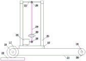
Fig. 4 is a schematic structural diagram of the automatic traveling washing and drying unit of the invention.
Fig. 5 is a schematic diagram of the control principle of the present invention.
Detailed Description
In order to more clearly understand the technical features, objects, and effects of the present invention, embodiments of the present invention will now be described with reference to the accompanying drawings, in which like reference numerals refer to like parts throughout. For the sake of simplicity, only the parts relevant to the invention are schematically shown in the drawings, and they do not represent the actual structure as a product.
As shown in fig. 1-5, the present invention relates to an automatic washing device for high efficiency bag-type dust removal and a washing and drying method, wherein the automatic washing device comprises a bag-type dust removal box 9, a plurality of dust removal bags 8 arranged in the bag-type dust removal box 9, the plurality of dust removal bags 8 are divided into a plurality of rows arranged at the upper inner part of the bag-type dust removal box 9, and a group of automatic traveling washing and drying units is correspondingly arranged at the bottom of each row of dust removal bags 8; the automatic walking washing and drying unit comprises a horizontal walking part, a vertical walking part and a washing and drying part connected with the vertical walking part; a washing nozzle 33 in the washing drying part is connected with a first tee joint 6 through a hose 5 with a control valve 4, and the second end of the first tee joint 6 is connected with a cloth bag washing water tank 1 through a water pipe stop valve 27 and an automatic washing water pump 3 in sequence; the third end of the first tee joint 6 is connected with a water return port of the cloth bag flushing water tank 1 through a second tee joint 7 and a flushing water return valve 2, and the third end of the second tee joint 7 is connected with an air drying fan 40 through an air pipe cut-off valve 42 and the shell pass of an air heat exchanger 41. Automatic walking is washed being equipped with of stoving unit bottom and is washed waste water discharge unit, wash waste water discharge unit includes that the board 11 is turned over on the articulated left side that links to each other with sack dust removal case 9 inner wall and the board 12 is turned over on the right side, the left side turns over the lower part that board 11 and right side turned over board 12 and is equipped with hydraulic cylinder 13 that links to each other with sack dust removal case 9 inner wall respectively, the left side is turned over and is installed on the corresponding sack dust removal case 9 inner wall in board 11 upper portion and is washed waste water discharge pipe 10, wash waste water discharge pipe 10 and link to each other with waste liquid recovery unit 16 through washing waste. The horizontal walking part comprises a horizontal walking motor 17 arranged on one side inside the cloth bag dust removing box 9, two first driving sprockets 18 are sleeved on a main shaft of the horizontal walking motor 17, a first shaft 19 is arranged on the other side inside the cloth bag dust removing box 9, two first driven sprockets 20 are sleeved on the first shaft 19, a first chain 21 is arranged between the first driving sprocket 18 and the first driven sprocket 20 corresponding to the first driving sprocket 18, and a vertical walking part mounting plate 22 is arranged between the two first chains. The horizontal traveling motor 17 is arranged at the top of a motor base 23 on the inner wall of the cloth bag dust removal box 9, bearing seats are respectively arranged at two ends of the first shaft 19, and the bearing seats are connected with the inner wall of the other side of the cloth bag dust removal box 9. The vertical walking part comprises a vertical walking motor 24 arranged in the middle of the top of the vertical walking part mounting plate 22, support frames 25 are arranged on two sides of the top of the vertical walking part mounting plate 22, bearings are respectively arranged at the top ends of the support frames 25, a second shaft 27 with two second driven sprockets 26 is arranged between the two bearings, two second driving sprockets 28 are arranged on a main shaft of the vertical walking motor 24, second chains 29 are arranged between the second driven sprockets 26 and the second driving sprockets 28 corresponding to the second driven sprockets 26, and a washing and drying part mounting plate 30 is arranged between the two second chains 29. The washing and drying part comprises a washing and drying ring 31 connected with a washing and drying part mounting plate 30, a plurality of groups of brushes 32, a plurality of washing nozzles 33 respectively connected with the hoses 5 and an automatic induction probe 34 are uniformly distributed on the inner side of the washing and drying ring 31, and the automatic induction probe 34 is matched with induction screws 35 arranged on the upper part and the lower part of the dust removal cloth bag 8. The horizontal walking part and the vertical walking part are arranged at the outer side of the corresponding row of dust-removing cloth bags 8, and the washing drying part is arranged at the bottom of the corresponding row of dust-removing cloth bags 8. The water inlet of the cloth bag flushing water tank 1 is connected with an industrial water pipe network 36; the tube side inlet of the air heat exchanger 41 is connected with the production plant area residual hot water pipeline 37, and the tube side outlet of the air heat exchanger 41 is connected with the production plant area residual hot water recovery pipeline 38. The control valve 4, the automatic flushing water pump 3, the flushing water return valve 2, the air pipe cut-off valve 42, the hydraulic oil cylinder 13, the horizontal walking motor 17 and the vertical walking motor 24 are respectively connected with the signal output end of the PLC control system 39, and the input end of the PLC control system 39 is respectively connected with the automatic induction probe 34.
A washing and drying method of an efficient automatic bag-type dust removal washing device comprises the following steps:
step 1: the bag-type dust collector operates normally to remove dust, pulse back flushing is carried out after the bag-type dust collector operates for a period of time, and when the pressure difference in the bag-type dust collector after the pulse back flushing is 0.2-0.5Kpa, the dust removing bag 8 is flushed;
step 2: the PLC control system 39 controls the hydraulic oil cylinder 13 to start, so that the telescopic end of the hydraulic oil cylinder 13 extends out, the left turning plate 11 and the right turning plate 12 are driven to run upwards, and the left turning plate 11 and the right turning plate 12 are closed to form a sealed washing space at the upper part of the cloth bag dust removal box 9;
and step 3: industrial water in the industrial water pipe network 36 enters the cloth bag flushing water tank 1 through a water inlet of the cloth bag flushing water tank 1, a water pipe stop valve 27 is opened, the PLC control system 39 controls the control valve 4 and the air pipe stop valve 42 to be closed, the flushing water return valve 2 is opened, the automatic flushing water pump 3 is started, and the industrial water in the cloth bag flushing water tank 1 enters the cloth bag flushing water tank 1 through the automatic flushing water pump 3, the water pipe stop valve 27, the flushing water return valve 2 and a water return port of the cloth bag flushing water tank 1; the industrial water pressure after passing through the automatic washing water pump 3 is as follows: 1.0-2.0 Mpa;
and 4, step 4: the PLC control system 39 controls a plurality of horizontal traveling motors 17 to start simultaneously, at the moment, the washing and drying ring 31 is positioned at the bottom of the dust removal cloth bag 8, the main shaft of the horizontal traveling motor 17 starts to rotate and drives the two first driving chain wheels 18 to synchronously rotate, the two first driving chain wheels 18 synchronously rotate and simultaneously drive the vertical traveling part mounting plate 22 to generate displacement, when the automatic induction probe 34 in the washing and drying ring 31 induces the induction screw 35, the automatic induction probe 34 sends a signal to the PLC control system 39, the PLC control system 39 controls the corresponding control valve 4 to open, the washing water return valve 2 is closed, the vertical walking motor 24 is controlled to start, the main shaft of the vertical walking motor starts to rotate and drives the two second driving sprockets 28 to synchronously rotate, and the two second driving sprockets 28 synchronously rotate and drive the washing and drying ring 31 to move upwards through the second chain 29 and the washing and drying part mounting plate 30; when the washing and drying ring 31 moves upwards, the industrial water washes the dust removal cloth bag 8 through the automatic washing water pump 3, the water pipe shut-off valve 27, the control valve 4, the hose 5 and the washing nozzle 33;
and 5: in the process of cleaning the dust removal cloth bag 8, the vertical walking motor 24 is in a running state, the second chain 29 drives the washing and drying ring 31 through the washing and drying part mounting plate 30 to clean the dust removal cloth bag 8 from bottom to top, and when the automatic induction probe 34 in the washing and drying ring 31 induces the induction screw 35, the PLC control system 39 controls the vertical walking motor 24 to stop running, and simultaneously closes the control valve 4 to stop washing the dust removal cloth bag 8; after the washing of the dust removal cloth bag 8 is stopped, the PLC control system 39 enters a top-down washing program, the PLC control system 39 controls the vertical walking motor 24 to rotate reversely, the second chain 29 drives the washing and drying ring 31 to run from top to bottom through the washing and drying part mounting plate 30, meanwhile, the PLC control system 39 controls the washing water return valve 2 to be closed, meanwhile, the control valve 4 is opened, industrial water washes the dust removal cloth bag 8 from top to bottom through the washing nozzle 33, and until the automatic induction probe 34 in the washing and drying ring 31 senses the induction screw 35, the PLC control system 39 controls the vertical walking motor 24 to stop running and the control valve 4 to be closed; the washing from bottom to top and the washing from top to bottom are a washing period, and the time of the washing period is 40-50 s;
step 6: after the washing period in step 5 is over, the PLC control system 39 controls the horizontal traveling motor 17 to start, at this time, the washing and drying ring 31 is still at the bottom of the dust-removing cloth bag 8, the main shaft of the horizontal traveling motor 17 starts to rotate and drives the two first driving sprockets 18 to synchronously rotate, the two first driving sprockets 18 synchronously rotate and simultaneously drive the vertical traveling part mounting plate 22 to generate displacement, when the automatic induction probe 34 in the washing and drying ring 31 induces the next induction screw 35, the automatic induction probe 34 sends a signal to the PLC control system 39, the PLC control system 39 controls the corresponding control valve 4 to open, the vertical walking motor 24 is controlled to start, the main shaft of the vertical walking motor starts to rotate and drives the two second driving sprockets 28 to synchronously rotate, and the two second driving sprockets 28 synchronously rotate and drive the washing and drying ring 31 to move upwards through the second chain 29 and the washing and drying part mounting plate 30; and repeating the step 5 to wash the next dust removal cloth bag 8 for one washing period;
and 7: the wastewater washed in the step 4, the step 5 and the step 6 enters the sealed washing space in the step 2 under the action of self weight, enters a washing wastewater tank 14 through a washing wastewater discharge pipeline 10, and is discharged into a wastewater recovery device 16 through a wastewater discharge pump 15 at the outlet of the washing wastewater tank 14 in a pressurizing manner;
and 8: after all the dust removing cloth bags 8 are cleaned, the PLC control system 39 controls the horizontal walking motors 17 to be started respectively, so that the vertical walking part mounting plate 22 returns to the initial position and enters a drying procedure;
and step 9: closing the water pipe shut-off valve 27, and simultaneously controlling the automatic washing water pump 3 and the washing water return valve 2 to be closed by the PLC control system 39; the PLC control system 39 controls a plurality of horizontal traveling motors 17 to start simultaneously, and at the moment, the washing and drying ring 31 is positioned at the bottom of the dust removal cloth bag 8; the main shaft of the horizontal walking motor 17 starts to rotate and drives the two first driving sprockets 18 to synchronously rotate, the two first driving sprockets 18 synchronously rotate and simultaneously drive the vertical walking part mounting plate 22 to displace, when the automatic induction probe 34 in the washing and drying ring 31 senses the induction screw 35, the air drying fan 40 is started, the automatic induction probe 34 sends a signal to the PLC control system 39, the PLC control system 39 controls the air pipe cut-off valve 42 and the corresponding control valve 4 to be opened, the vertical walking motor 24 is simultaneously controlled to start, the main shaft of the vertical walking motor starts to rotate and drives the two second driving sprockets 28 to synchronously rotate, and the washing and drying ring 31 is driven to move upwards by the second chain 29 and the washing and drying part mounting plate 30 while the two second driving sprockets 28 synchronously rotate; when the washing and drying ring 31 moves upwards, the air generated by the air drying fan 40 is subjected to heat exchange through the shell pass of the air heat exchanger 41, and then is dried and blown to the dust removal cloth bag 8 through the air pipe cut-off valve 42, the control valve 4, the hose 5 and the washing nozzle 33;
step 10: in the process of drying and blowing the dust removal cloth bag 8, the air drying fan 40 and the vertical traveling motor 24 are in a running state, the second chain 29 drives the washing and drying ring 31 through the washing and drying part mounting plate 30 to dry and blow the dust removal cloth bag 8 from bottom to top, and when the automatic induction probe 34 in the washing and drying ring 31 senses the induction screw 35, the automatic induction probe 34 controls the vertical traveling motor 24 to stop running through the PLC control system 39; after the vertical walking motor 24 stops running, the PLC control system 39 enters a top-down drying and blowing program, the PLC control system 39 controls the vertical walking motor 24 to rotate reversely, the second chain 29 drives the washing and drying ring 31 to run from top to bottom through the washing and drying part mounting plate 30, hot air carries out top-down drying and blowing on the dust removal cloth bag 8 through the washing and drying nozzle 33, and the PLC control system 39 controls the vertical walking motor 24 to stop running until the automatic induction probe 34 in the washing and drying ring 31 senses the induction screw 35; the bottom-up drying and blowing and the top-down drying and blowing are a drying and blowing period, and the time of the drying and blowing period is 40-50 s;
step 11: after the drying and blowing period in the step 10 is finished, the PLC control system 39 controls the horizontal traveling motor 17 to start, and at the moment, the washing and drying ring 31 is still positioned at the bottom of the dust removal cloth bag 8; the main shaft of the horizontal walking motor 17 starts to rotate and drives the two first driving sprockets 18 to synchronously rotate, the two first driving sprockets 18 synchronously rotate and simultaneously drive the vertical walking part mounting plate 22 to generate displacement, when the automatic induction probe 34 in the washing and drying ring 31 senses the next induction screw 35, the automatic induction probe 35 sends a signal to the PLC control system 39, the PLC control system 39 controls the vertical walking motor 24 to start, the main shaft of the vertical walking motor starts to rotate and drives the two second driving sprockets 28 to synchronously rotate, and the two second driving sprockets 28 synchronously rotate and simultaneously drive the washing and drying ring 31 to move upwards through the second chain 29 and the washing and drying part mounting plate 30; repeating the step 10 to dry the next dust removal cloth bag 8 for one drying and blowing period;
step 12: in the above steps 4, 6, 8, 9 and 11, the PLC control system 39 controls the plurality of horizontal traveling motors 17 respectively, and the plurality of horizontal traveling motors 17 run asynchronously;
step 13: after all the dust removing cloth bags 8 are dried, the PLC control system 39 controls the hydraulic oil cylinder 13 to be started, so that the telescopic end of the hydraulic oil cylinder 13 retracts, the left turning plate 11 and the right turning plate 12 are driven to run downwards, and at the moment, the cloth bag dust remover enters a normal dust removing running state.
The tube pass of the air heat exchanger 41 in the invention mainly uses the waste heat, when the temperature of the waste heat is high, the frequency of the vertical walking motor 24 can be properly accelerated in the drying process, so that the operation speed of the washing and drying part is slightly higher; when the temperature of the waste heat is low, the frequency of the vertical traveling motor 24 can be properly slowed down in the drying process, so that the running speed of the washing and drying part is slower, and the aim of completely drying the dust removal cloth bag 8 is fulfilled; the automatic induction probe and the induction screw can be directly purchased in the market, and the structure of the automatic induction probe and the induction screw is not described in detail. The power of the hydraulic oil cylinder 13 in the invention is from a hydraulic oil station with a hydraulic oil pump, and the power is in a conventional arrangement and is not described again; the hydraulic oil station uses conventional hydraulic oil, the pressure of the oil station is controlled to be 1.4-1.8Mpa, the hydraulic oil station drives the left turning plate 11 and the right turning plate 12 to open and close under the action of a hydraulic oil pump, L-shaped sealing plates are respectively arranged at the tail ends of the left turning plate 11 and the right turning plate 12, the long edge of the L-shaped sealing plate of the left turning plate 11 is arranged at the upper part, and the short edge of the L-shaped sealing plate of the left turning plate 11 is arranged; the L-shaped sealing plate short edge of the right turning plate 12 is arranged on the upper portion, the long edge is arranged on the lower portion, when the two are closed, the sealing of the upper space of the cloth bag dust removal box 9 can be achieved to prevent washing water from leaking, and when the left turning plate 11 and the right turning plate 12 are closed, the height of the joint of the left turning plate 11 and the right turning plate 12 is larger than the height around, so that the purpose that washing wastewater flows around from the middle is achieved. In addition, the turning plates in the invention can be two, three or four, so as to achieve the aim of sealing the flushing space. The number of the first chains 21 and the second chains 29 is at least two respectively, so that the purpose of normally operating the whole equipment is achieved.
The present invention will now be further illustrated with reference to examples in order to explain the present invention in more detail. The specific embodiment is as follows:
example one
An efficient automatic washing device for bag-type dust removal comprises a bag-type dust removal box 9, a plurality of dust removal bags 8 arranged in the bag-type dust removal box 9, wherein the dust removal bags 8 are divided into a plurality of rows and arranged at the upper inner part of the bag-type dust removal box 9, and a group of automatic walking washing and drying units are correspondingly arranged at the bottom of each row of dust removal bags 8; the automatic walking washing and drying unit comprises a horizontal walking part, a vertical walking part and a washing and drying part connected with the vertical walking part; a washing nozzle 33 in the washing drying part is connected with a first tee joint 6 through a hose 5 with a control valve 4, and the second end of the first tee joint 6 is connected with a cloth bag washing water tank 1 through a water pipe stop valve 27 and an automatic washing water pump 3 in sequence; the third end of the first tee joint 6 is connected with a water return port of the cloth bag flushing water tank 1 through a second tee joint 7 and a flushing water return valve 2, and the third end of the second tee joint 7 is connected with an air drying fan 40 through an air pipe cut-off valve 42 and the shell pass of an air heat exchanger 41. Automatic walking is washed being equipped with of stoving unit bottom and is washed waste water discharge unit, wash waste water discharge unit includes that the board 11 is turned over on the articulated left side that links to each other with sack dust removal case 9 inner wall and the board 12 is turned over on the right side, the left side turns over the lower part that board 11 and right side turned over board 12 and is equipped with hydraulic cylinder 13 that links to each other with sack dust removal case 9 inner wall respectively, the left side is turned over and is installed on the corresponding sack dust removal case 9 inner wall in board 11 upper portion and is washed waste water discharge pipe 10, wash waste water discharge pipe 10 and link to each other with waste liquid recovery unit 16 through washing waste. The horizontal walking part comprises a horizontal walking motor 17 arranged on one side inside the cloth bag dust removing box 9, two first driving sprockets 18 are sleeved on a main shaft of the horizontal walking motor 17, a first shaft 19 is arranged on the other side inside the cloth bag dust removing box 9, two first driven sprockets 20 are sleeved on the first shaft 19, a first chain 21 is arranged between the first driving sprocket 18 and the first driven sprocket 20 corresponding to the first driving sprocket 18, and a vertical walking part mounting plate 22 is arranged between the two first chains 21. The horizontal traveling motor 17 is arranged at the top of a motor base 23 on the inner wall of the cloth bag dust removal box 9, bearing seats are respectively arranged at two ends of the first shaft 19, and the bearing seats are connected with the inner wall of the other side of the cloth bag dust removal box 9. The vertical walking part comprises a vertical walking motor 24 arranged in the middle of the top of the vertical walking part mounting plate 22, support frames 25 are arranged on two sides of the top of the vertical walking part mounting plate 22, bearings are respectively arranged at the top ends of the support frames 25, a second shaft 27 with two second driven sprockets 26 is arranged between the two bearings, two second driving sprockets 28 are arranged on a main shaft of the vertical walking motor 24, second chains 29 are arranged between the second driven sprockets 26 and the second driving sprockets 28 corresponding to the second driven sprockets 26, and a washing and drying part mounting plate 30 is arranged between the two second chains 29. The washing and drying part comprises a washing and drying ring 31 connected with a washing and drying part mounting plate 30, a plurality of groups of brushes 32, a plurality of washing nozzles 33 respectively connected with the hoses 5 and an automatic induction probe 34 are uniformly distributed on the inner side of the washing and drying ring 31, and the automatic induction probe 34 is matched with induction screws 35 arranged on the upper part and the lower part of the dust removal cloth bag 8. The horizontal walking part and the vertical walking part are arranged at the outer side of the corresponding row of dust-removing cloth bags 8, and the washing drying part is arranged at the bottom of the corresponding row of dust-removing cloth bags 8. The water inlet of the cloth bag flushing water tank 1 is connected with an industrial water pipe network 36; the tube side inlet of the air heat exchanger 41 is connected with the production plant area residual hot water pipeline 37, and the tube side outlet of the air heat exchanger 41 is connected with the production plant area residual hot water recovery pipeline 38. The control valve 4, the automatic flushing water pump 3, the flushing water return valve 2, the air pipe cut-off valve 42, the hydraulic oil cylinder 13, the horizontal walking motor 17 and the vertical walking motor 24 are respectively connected with the signal output end of the PLC control system 39, and the input end of the PLC control system 39 is respectively connected with the automatic induction probe 34.
A washing and drying method of an efficient automatic bag-type dust removal washing device comprises the following steps:
step 1: the bag-type dust collector operates normally to remove dust, pulse back flushing is carried out after the bag-type dust collector operates for a period of time, and when the pressure difference in the bag-type dust collector after the pulse back flushing is 0.2Kpa, the dust-removing bag 8 is flushed;
step 2: the PLC control system 39 controls the hydraulic oil cylinder 13 to start, so that the telescopic end of the hydraulic oil cylinder 13 extends out, the left turning plate 11 and the right turning plate 12 are driven to run upwards, and the left turning plate 11 and the right turning plate 12 are closed to form a sealed washing space at the upper part of the cloth bag dust removal box 9;
and step 3: industrial water in the industrial water pipe network 36 enters the cloth bag flushing water tank 1 through a water inlet of the cloth bag flushing water tank 1, a water pipe stop valve 27 is opened, the PLC control system 39 controls the control valve 4 and the air pipe stop valve 42 to be closed, the flushing water return valve 2 is opened, the automatic flushing water pump 3 is started, and the industrial water in the cloth bag flushing water tank 1 enters the cloth bag flushing water tank 1 through the automatic flushing water pump 3, the water pipe stop valve 27, the flushing water return valve 2 and a water return port of the cloth bag flushing water tank 1; the industrial water pressure after passing through the automatic washing water pump 3 is as follows: 1.0 Mpa;
and 4, step 4: the PLC control system 39 controls a plurality of horizontal traveling motors 17 to start simultaneously, at the moment, the washing and drying ring 31 is positioned at the bottom of the dust removal cloth bag 8, the main shaft of the horizontal traveling motor 17 starts to rotate and drives the two first driving chain wheels 18 to synchronously rotate, the two first driving chain wheels 18 synchronously rotate and simultaneously drive the vertical traveling part mounting plate 22 to generate displacement, when the automatic induction probe 34 in the washing and drying ring 31 induces the induction screw 35, the automatic induction probe 34 sends a signal to the PLC control system 39, the PLC control system 39 controls the corresponding control valve 4 to open, the washing water return valve 2 is closed, the vertical walking motor 24 is controlled to start, the main shaft of the vertical walking motor starts to rotate and drives the two second driving sprockets 28 to synchronously rotate, and the two second driving sprockets 28 synchronously rotate and drive the washing and drying ring 31 to move upwards through the second chain 29 and the washing and drying part mounting plate 30; when the washing and drying ring 31 moves upwards, the industrial water washes the dust removal cloth bag 8 through the automatic washing water pump 3, the water pipe shut-off valve 27, the control valve 4, the hose 5 and the washing nozzle 33;
and 5: in the process of cleaning the dust removal cloth bag 8, the vertical walking motor 24 is in a running state, the second chain 29 drives the washing and drying ring 31 through the washing and drying part mounting plate 30 to clean the dust removal cloth bag 8 from bottom to top, and when the automatic induction probe 34 in the washing and drying ring 31 induces the induction screw 35, the PLC control system 39 controls the vertical walking motor 24 to stop running, and simultaneously closes the control valve 4 to stop washing the dust removal cloth bag 8; after the washing of the dust removal cloth bag 8 is stopped, the PLC control system 39 enters a top-down washing program, the PLC control system 39 controls the vertical walking motor 24 to rotate reversely, the second chain 29 drives the washing and drying ring 31 to run from top to bottom through the washing and drying part mounting plate 30, meanwhile, the PLC control system 39 controls the washing water return valve 2 to be closed, meanwhile, the control valve 4 is opened, industrial water washes the dust removal cloth bag 8 from top to bottom through the washing nozzle 33, and until the automatic induction probe 34 in the washing and drying ring 31 senses the induction screw 35, the PLC control system 39 controls the vertical walking motor 24 to stop running and the control valve 4 to be closed; the washing from bottom to top and the washing from top to bottom are a washing period, and the time of the washing period is 40-50 s;
step 6: after the washing period in step 5 is over, the PLC control system 39 controls the horizontal traveling motor 17 to start, at this time, the washing and drying ring 31 is still at the bottom of the dust-removing cloth bag 8, the main shaft of the horizontal traveling motor 17 starts to rotate and drives the two first driving sprockets 18 to synchronously rotate, the two first driving sprockets 18 synchronously rotate and simultaneously drive the vertical traveling part mounting plate 22 to generate displacement, when the automatic induction probe 34 in the washing and drying ring 31 induces the next induction screw 35, the automatic induction probe 34 sends a signal to the PLC control system 39, the PLC control system 39 controls the corresponding control valve 4 to open, the vertical walking motor 24 is controlled to start, the main shaft of the vertical walking motor starts to rotate and drives the two second driving sprockets 28 to synchronously rotate, and the two second driving sprockets 28 synchronously rotate and drive the washing and drying ring 31 to move upwards through the second chain 29 and the washing and drying part mounting plate 30; and repeating the step 5 to wash the next dust removal cloth bag 8 for one washing period;
and 7: the wastewater washed in the step 4, the step 5 and the step 6 enters the sealed washing space in the step 2 under the action of self weight, enters a washing wastewater tank 14 through a washing wastewater discharge pipeline 10, and is discharged into a wastewater recovery device 16 through a wastewater discharge pump 15 at the outlet of the washing wastewater tank 14 in a pressurizing manner;
and 8: after all the dust removing cloth bags 8 are cleaned, the PLC control system 39 controls the horizontal walking motors 17 to be started respectively, so that the vertical walking part mounting plate 22 returns to the initial position and enters a drying procedure;
and step 9: closing the water pipe shut-off valve 27, and simultaneously controlling the automatic washing water pump 3 and the washing water return valve 2 to be closed by the PLC control system 39; the PLC control system 39 controls a plurality of horizontal traveling motors 17 to start simultaneously, and at the moment, the washing and drying ring 31 is positioned at the bottom of the dust removal cloth bag 8; the main shaft of the horizontal walking motor 17 starts to rotate and drives the two first driving sprockets 18 to synchronously rotate, the two first driving sprockets 18 synchronously rotate and simultaneously drive the vertical walking part mounting plate 22 to displace, when the automatic induction probe 34 in the washing and drying ring 31 senses the induction screw 35, the air drying fan 40 is started, the automatic induction probe 34 sends a signal to the PLC control system 39, the PLC control system 39 controls the air pipe cut-off valve 42 and the corresponding control valve 4 to be opened, the vertical walking motor 24 is simultaneously controlled to start, the main shaft of the vertical walking motor starts to rotate and drives the two second driving sprockets 28 to synchronously rotate, and the washing and drying ring 31 is driven to move upwards by the second chain 29 and the washing and drying part mounting plate 30 while the two second driving sprockets 28 synchronously rotate; when the washing and drying ring 31 moves upwards, the air generated by the air drying fan 40 is subjected to heat exchange through the shell pass of the air heat exchanger 41, and then is dried and blown to the dust removal cloth bag 8 through the air pipe cut-off valve 42, the control valve 4, the hose 5 and the washing nozzle 33;
step 10: in the process of drying and blowing the dust removal cloth bag 8, the air drying fan 40 and the vertical traveling motor 24 are in a running state, the second chain 29 drives the washing and drying ring 31 through the washing and drying part mounting plate 30 to dry and blow the dust removal cloth bag 8 from bottom to top, and when the automatic induction probe 34 in the washing and drying ring 31 senses the induction screw 35, the automatic induction probe 34 controls the vertical traveling motor 24 to stop running through the PLC control system 39; after the vertical walking motor 24 stops running, the PLC control system 39 enters a top-down drying and blowing program, the PLC control system 39 controls the vertical walking motor 24 to rotate reversely, the second chain 29 drives the washing and drying ring 31 to run from top to bottom through the washing and drying part mounting plate 30, hot air carries out top-down drying and blowing on the dust removal cloth bag 8 through the washing and drying nozzle 33, and the PLC control system 39 controls the vertical walking motor 24 to stop running until the automatic induction probe 34 in the washing and drying ring 31 senses the induction screw 35; the bottom-up drying and blowing and the top-down drying and blowing are a drying and blowing period, and the time of the drying and blowing period is 40-50 s;
step 11: after the drying and blowing period in the step 10 is finished, the PLC control system 39 controls the horizontal traveling motor 17 to start, and at the moment, the washing and drying ring 31 is still positioned at the bottom of the dust removal cloth bag 8; the main shaft of the horizontal walking motor 17 starts to rotate and drives the two first driving sprockets 18 to synchronously rotate, the two first driving sprockets 18 synchronously rotate and simultaneously drive the vertical walking part mounting plate 22 to generate displacement, when the automatic induction probe 34 in the washing and drying ring 31 senses the next induction screw 35, the automatic induction probe 35 sends a signal to the PLC control system 39, the PLC control system 39 controls the vertical walking motor 24 to start, the main shaft of the vertical walking motor starts to rotate and drives the two second driving sprockets 28 to synchronously rotate, and the two second driving sprockets 28 synchronously rotate and simultaneously drive the washing and drying ring 31 to move upwards through the second chain 29 and the washing and drying part mounting plate 30; repeating the step 10 to dry the next dust removal cloth bag 8 for one drying and blowing period;
step 12: the PLC control system 39 in the steps 4, 6, 8, 9 and 11 respectively controls the plurality of horizontal traveling motors 17, and the plurality of horizontal traveling motors 17 run asynchronously;
step 13: after all the dust removing cloth bags 8 are dried, the PLC control system 39 controls the hydraulic oil cylinder 13 to be started, so that the telescopic end of the hydraulic oil cylinder 13 retracts, the left turning plate 11 and the right turning plate 12 are driven to run downwards, and at the moment, the cloth bag dust remover enters a normal dust removing running state.
Example two
An efficient automatic washing device for bag-type dust removal comprises a bag-type dust removal box 9, a plurality of dust removal bags 8 arranged in the bag-type dust removal box 9, wherein the dust removal bags 8 are divided into a plurality of rows and arranged at the upper inner part of the bag-type dust removal box 9, and a group of automatic walking washing and drying units are correspondingly arranged at the bottom of each row of dust removal bags 8; the automatic walking washing and drying unit comprises a horizontal walking part, a vertical walking part and a washing and drying part connected with the vertical walking part; a washing nozzle 33 in the washing drying part is connected with a first tee joint 6 through a hose 5 with a control valve 4, and the second end of the first tee joint 6 is connected with a cloth bag washing water tank 1 through a water pipe stop valve 27 and an automatic washing water pump 3 in sequence; the third end of the first tee joint 6 is connected with a water return port of the cloth bag flushing water tank 1 through a second tee joint 7 and a flushing water return valve 2, and the third end of the second tee joint 7 is connected with an air drying fan 40 through an air pipe cut-off valve 42 and the shell pass of an air heat exchanger 41. Automatic walking is washed being equipped with of stoving unit bottom and is washed waste water discharge unit, wash waste water discharge unit includes that the board 11 is turned over on the articulated left side that links to each other with sack dust removal case 9 inner wall and the board 12 is turned over on the right side, the left side turns over the lower part that board 11 and right side turned over board 12 and is equipped with hydraulic cylinder 13 that links to each other with sack dust removal case 9 inner wall respectively, the left side is turned over and is installed on the corresponding sack dust removal case 9 inner wall in board 11 upper portion and is washed waste water discharge pipe 10, wash waste water discharge pipe 10 and link to each other with waste liquid recovery unit 16 through washing waste. The horizontal walking part comprises a horizontal walking motor 17 arranged on one side inside the cloth bag dust removing box 9, two first driving sprockets 18 are sleeved on a main shaft of the horizontal walking motor 17, a first shaft 19 is arranged on the other side inside the cloth bag dust removing box 9, two first driven sprockets 20 are sleeved on the first shaft 19, a first chain 21 is arranged between the first driving sprocket 18 and the first driven sprocket 20 corresponding to the first driving sprocket 18, and a vertical walking part mounting plate 22 is arranged between the two first chains 21. The horizontal traveling motor 17 is arranged at the top of a motor base 23 on the inner wall of the cloth bag dust removal box 9, bearing seats are respectively arranged at two ends of the first shaft 19, and the bearing seats are connected with the inner wall of the other side of the cloth bag dust removal box 9. The vertical walking part comprises a vertical walking motor 24 arranged in the middle of the top of the vertical walking part mounting plate 22, support frames 25 are arranged on two sides of the top of the vertical walking part mounting plate 22, bearings are respectively arranged at the top ends of the support frames 25, a second shaft 27 with two second driven sprockets 26 is arranged between the two bearings, two second driving sprockets 28 are arranged on a main shaft of the vertical walking motor 24, second chains 29 are arranged between the second driven sprockets 26 and the second driving sprockets 28 corresponding to the second driven sprockets 26, and a washing and drying part mounting plate 30 is arranged between the two second chains 29. The washing and drying part comprises a washing and drying ring 31 connected with a washing and drying part mounting plate 30, a plurality of groups of brushes 32, a plurality of washing nozzles 33 respectively connected with the hoses 5 and an automatic induction probe 34 are uniformly distributed on the inner side of the washing and drying ring 31, and the automatic induction probe 34 is matched with induction screws 35 arranged on the upper part and the lower part of the dust removal cloth bag 8. The horizontal walking part and the vertical walking part are arranged at the outer side of the corresponding row of dust-removing cloth bags 8, and the washing drying part is arranged at the bottom of the corresponding row of dust-removing cloth bags 8. The water inlet of the cloth bag flushing water tank 1 is connected with an industrial water pipe network 36; the tube side inlet of the air heat exchanger 41 is connected with the production plant area residual hot water pipeline 37, and the tube side outlet of the air heat exchanger 41 is connected with the production plant area residual hot water recovery pipeline 38. The control valve 4, the automatic flushing water pump 3, the flushing water return valve 2, the air pipe cut-off valve 42, the hydraulic oil cylinder 13, the horizontal walking motor 17 and the vertical walking motor 24 are respectively connected with the signal output end of the PLC control system 39, and the input end of the PLC control system 39 is respectively connected with the automatic induction probe 34.
A washing and drying method of an efficient automatic bag-type dust removal washing device comprises the following steps:
step 1: the bag-type dust collector operates normally to remove dust, pulse back flushing is carried out after the bag-type dust collector operates for a period of time, and when the pressure difference in the bag-type dust collector after the pulse back flushing is 0.5Kpa, the dust-removing bag 8 is flushed;
step 2: the PLC control system 39 controls the hydraulic oil cylinder 13 to start, so that the telescopic end of the hydraulic oil cylinder 13 extends out, the left turning plate 11 and the right turning plate 12 are driven to run upwards, and the left turning plate 11 and the right turning plate 12 are closed to form a sealed washing space at the upper part of the cloth bag dust removal box 9;
and step 3: industrial water in the industrial water pipe network 36 enters the cloth bag flushing water tank 1 through a water inlet of the cloth bag flushing water tank 1, a water pipe stop valve 27 is opened, the PLC control system 39 controls the control valve 4 and the air pipe stop valve 42 to be closed, the flushing water return valve 2 is opened, the automatic flushing water pump 3 is started, and the industrial water in the cloth bag flushing water tank 1 enters the cloth bag flushing water tank 1 through the automatic flushing water pump 3, the water pipe stop valve 27, the flushing water return valve 2 and a water return port of the cloth bag flushing water tank 1; the industrial water pressure after passing through the automatic washing water pump 3 is as follows: 2.0 Mpa;
and 4, step 4: the PLC control system 39 controls a plurality of horizontal traveling motors 17 to start simultaneously, at the moment, the washing and drying ring 31 is positioned at the bottom of the dust removal cloth bag 8, the main shaft of the horizontal traveling motor 17 starts to rotate and drives the two first driving chain wheels 18 to synchronously rotate, the two first driving chain wheels 18 synchronously rotate and simultaneously drive the vertical traveling part mounting plate 22 to generate displacement, when the automatic induction probe 34 in the washing and drying ring 31 induces the induction screw 35, the automatic induction probe 34 sends a signal to the PLC control system 39, the PLC control system 39 controls the corresponding control valve 4 to open, the washing water return valve 2 is closed, the vertical walking motor 24 is controlled to start, the main shaft of the vertical walking motor starts to rotate and drives the two second driving sprockets 28 to synchronously rotate, and the two second driving sprockets 28 synchronously rotate and drive the washing and drying ring 31 to move upwards through the second chain 29 and the washing and drying part mounting plate 30; when the washing and drying ring 31 moves upwards, the industrial water washes the dust removal cloth bag 8 through the automatic washing water pump 3, the water pipe shut-off valve 27, the control valve 4, the hose 5 and the washing nozzle 33;
and 5: in the process of cleaning the dust removal cloth bag 8, the vertical walking motor 24 is in a running state, the second chain 29 drives the washing and drying ring 31 through the washing and drying part mounting plate 30 to clean the dust removal cloth bag 8 from bottom to top, and when the automatic induction probe 34 in the washing and drying ring 31 induces the induction screw 35, the PLC control system 39 controls the vertical walking motor 24 to stop running, and simultaneously closes the control valve 4 to stop washing the dust removal cloth bag 8; after the washing of the dust removal cloth bag 8 is stopped, the PLC control system 39 enters a top-down washing program, the PLC control system 39 controls the vertical walking motor 24 to rotate reversely, the second chain 29 drives the washing and drying ring 31 to run from top to bottom through the washing and drying part mounting plate 30, meanwhile, the PLC control system 39 controls the washing water return valve 2 to be closed, meanwhile, the control valve 4 is opened, industrial water washes the dust removal cloth bag 8 from top to bottom through the washing nozzle 33, and until the automatic induction probe 34 in the washing and drying ring 31 senses the induction screw 35, the PLC control system 39 controls the vertical walking motor 24 to stop running and the control valve 4 to be closed; the washing from bottom to top and the washing from top to bottom are a washing period, and the time of the washing period is 40-50 s;
step 6: after the washing period in step 5 is over, the PLC control system 39 controls the horizontal traveling motor 17 to start, at this time, the washing and drying ring 31 is still at the bottom of the dust-removing cloth bag 8, the main shaft of the horizontal traveling motor 17 starts to rotate and drives the two first driving sprockets 18 to synchronously rotate, the two first driving sprockets 18 synchronously rotate and simultaneously drive the vertical traveling part mounting plate 22 to generate displacement, when the automatic induction probe 34 in the washing and drying ring 31 induces the next induction screw 35, the automatic induction probe 34 sends a signal to the PLC control system 39, the PLC control system 39 controls the corresponding control valve 4 to open, the vertical walking motor 24 is controlled to start, the main shaft of the vertical walking motor starts to rotate and drives the two second driving sprockets 28 to synchronously rotate, and the two second driving sprockets 28 synchronously rotate and drive the washing and drying ring 31 to move upwards through the second chain 29 and the washing and drying part mounting plate 30; and repeating the step 5 to wash the next dust removal cloth bag 8 for one washing period;
and 7: the wastewater washed in the step 4, the step 5 and the step 6 enters the sealed washing space in the step 2 under the action of self weight, enters a washing wastewater tank 14 through a washing wastewater discharge pipeline 10, and is discharged into a wastewater recovery device 16 through a wastewater discharge pump 15 at the outlet of the washing wastewater tank 14 in a pressurizing manner;
and 8: after all the dust removing cloth bags 8 are cleaned, the PLC control system 39 controls the horizontal walking motors 17 to be started respectively, so that the vertical walking part mounting plate 22 returns to the initial position and enters a drying procedure;
and step 9: closing the water pipe shut-off valve 27, and simultaneously controlling the automatic washing water pump 3 and the washing water return valve 2 to be closed by the PLC control system 39; the PLC control system 39 controls a plurality of horizontal traveling motors 17 to start simultaneously, and at the moment, the washing and drying ring 31 is positioned at the bottom of the dust removal cloth bag 8; the main shaft of the horizontal walking motor 17 starts to rotate and drives the two first driving sprockets 18 to synchronously rotate, the two first driving sprockets 18 synchronously rotate and simultaneously drive the vertical walking part mounting plate 22 to displace, when the automatic induction probe 34 in the washing and drying ring 31 senses the induction screw 35, the air drying fan 40 is started, the automatic induction probe 34 sends a signal to the PLC control system 39, the PLC control system 39 controls the air pipe cut-off valve 42 and the corresponding control valve 4 to be opened, the vertical walking motor 24 is simultaneously controlled to start, the main shaft of the vertical walking motor starts to rotate and drives the two second driving sprockets 28 to synchronously rotate, and the washing and drying ring 31 is driven to move upwards by the second chain 29 and the washing and drying part mounting plate 30 while the two second driving sprockets 28 synchronously rotate; when the washing and drying ring 31 moves upwards, the air generated by the air drying fan 40 is subjected to heat exchange through the shell pass of the air heat exchanger 41, and then is dried and blown to the dust removal cloth bag 8 through the air pipe cut-off valve 42, the control valve 4, the hose 5 and the washing nozzle 33;
step 10: in the process of drying and blowing the dust removal cloth bag 8, the air drying fan 40 and the vertical traveling motor 24 are in a running state, the second chain 29 drives the washing and drying ring 31 through the washing and drying part mounting plate 30 to dry and blow the dust removal cloth bag 8 from bottom to top, and when the automatic induction probe 34 in the washing and drying ring 31 senses the induction screw 35, the automatic induction probe 34 controls the vertical traveling motor 24 to stop running through the PLC control system 39; after the vertical walking motor 24 stops running, the PLC control system 39 enters a top-down drying and blowing program, the PLC control system 39 controls the vertical walking motor 24 to rotate reversely, the second chain 29 drives the washing and drying ring 31 to run from top to bottom through the washing and drying part mounting plate 30, hot air carries out top-down drying and blowing on the dust removal cloth bag 8 through the washing and drying nozzle 33, and the PLC control system 39 controls the vertical walking motor 24 to stop running until the automatic induction probe 34 in the washing and drying ring 31 senses the induction screw 35; the bottom-up drying and blowing and the top-down drying and blowing are a drying and blowing period, and the time of the drying and blowing period is 40-50 s;
step 11: after the drying and blowing period in the step 10 is finished, the PLC control system 39 controls the horizontal traveling motor 17 to start, and at the moment, the washing and drying ring 31 is still positioned at the bottom of the dust removal cloth bag 8; the main shaft of the horizontal walking motor 17 starts to rotate and drives the two first driving sprockets 18 to synchronously rotate, the two first driving sprockets 18 synchronously rotate and simultaneously drive the vertical walking part mounting plate 22 to generate displacement, when the automatic induction probe 34 in the washing and drying ring 31 senses the next induction screw 35, the automatic induction probe 35 sends a signal to the PLC control system 39, the PLC control system 39 controls the vertical walking motor 24 to start, the main shaft of the vertical walking motor starts to rotate and drives the two second driving sprockets 28 to synchronously rotate, and the two second driving sprockets 28 synchronously rotate and simultaneously drive the washing and drying ring 31 to move upwards through the second chain 29 and the washing and drying part mounting plate 30; repeating the step 10 to dry the next dust removal cloth bag 8 for one drying and blowing period;
step 12: in the above steps 4, 6, 8, 9 and 11, the PLC control system 39 controls the plurality of horizontal traveling motors 17 respectively, and the plurality of horizontal traveling motors 17 run asynchronously;
step 13: after all the dust removing cloth bags 8 are dried, the PLC control system 39 controls the hydraulic oil cylinder 13 to be started, so that the telescopic end of the hydraulic oil cylinder 13 retracts, the left turning plate 11 and the right turning plate 12 are driven to run downwards, and at the moment, the cloth bag dust remover enters a normal dust removing running state.
EXAMPLE III
An efficient automatic washing device for bag-type dust removal comprises a bag-type dust removal box 9, a plurality of dust removal bags 8 arranged in the bag-type dust removal box 9, wherein the dust removal bags 8 are divided into a plurality of rows and arranged at the upper inner part of the bag-type dust removal box 9, and a group of automatic walking washing and drying units are correspondingly arranged at the bottom of each row of dust removal bags 8; the automatic walking washing and drying unit comprises a horizontal walking part, a vertical walking part and a washing and drying part connected with the vertical walking part; a washing nozzle 33 in the washing drying part is connected with a first tee joint 6 through a hose 5 with a control valve 4, and the second end of the first tee joint 6 is connected with a cloth bag washing water tank 1 through a water pipe stop valve 27 and an automatic washing water pump 3 in sequence; the third end of the first tee joint 6 is connected with a water return port of the cloth bag flushing water tank 1 through a second tee joint 7 and a flushing water return valve 2, and the third end of the second tee joint 7 is connected with an air drying fan 40 through an air pipe cut-off valve 42 and the shell pass of an air heat exchanger 41. Automatic walking is washed being equipped with of stoving unit bottom and is washed waste water discharge unit, wash waste water discharge unit includes that the board 11 is turned over on the articulated left side that links to each other with sack dust removal case 9 inner wall and the board 12 is turned over on the right side, the left side turns over the lower part that board 11 and right side turned over board 12 and is equipped with hydraulic cylinder 13 that links to each other with sack dust removal case 9 inner wall respectively, the left side is turned over and is installed on the corresponding sack dust removal case 9 inner wall in board 11 upper portion and is washed waste water discharge pipe 10, wash waste water discharge pipe 10 and link to each other with waste liquid recovery unit 16 through washing waste. The horizontal walking part comprises a horizontal walking motor 17 arranged on one side inside the cloth bag dust removing box 9, two first driving sprockets 18 are sleeved on a main shaft of the horizontal walking motor 17, a first shaft 19 is arranged on the other side inside the cloth bag dust removing box 9, two first driven sprockets 20 are sleeved on the first shaft 19, a first chain 21 is arranged between the first driving sprocket 18 and the first driven sprocket 20 corresponding to the first driving sprocket 18, and a vertical walking part mounting plate 22 is arranged between the two first chains 21. The horizontal traveling motor 17 is arranged at the top of a motor base 23 on the inner wall of the cloth bag dust removal box 9, bearing seats are respectively arranged at two ends of the first shaft 19, and the bearing seats are connected with the inner wall of the other side of the cloth bag dust removal box 9. The vertical walking part comprises a vertical walking motor 24 arranged in the middle of the top of the vertical walking part mounting plate 22, support frames 25 are arranged on two sides of the top of the vertical walking part mounting plate 22, bearings are respectively arranged at the top ends of the support frames 25, a second shaft 27 with two second driven sprockets 26 is arranged between the two bearings, two second driving sprockets 28 are arranged on a main shaft of the vertical walking motor 24, second chains 29 are arranged between the second driven sprockets 26 and the second driving sprockets 28 corresponding to the second driven sprockets 26, and a washing and drying part mounting plate 30 is arranged between the two second chains 29. The washing and drying part comprises a washing and drying ring 31 connected with a washing and drying part mounting plate 30, a plurality of groups of brushes 32, a plurality of washing nozzles 33 respectively connected with the hoses 5 and an automatic induction probe 34 are uniformly distributed on the inner side of the washing and drying ring 31, and the automatic induction probe 34 is matched with induction screws 35 arranged on the upper part and the lower part of the dust removal cloth bag 8. The horizontal walking part and the vertical walking part are arranged at the outer side of the corresponding row of dust-removing cloth bags 8, and the washing drying part is arranged at the bottom of the corresponding row of dust-removing cloth bags 8. The water inlet of the cloth bag flushing water tank 1 is connected with an industrial water pipe network 36; the tube side inlet of the air heat exchanger 41 is connected with the production plant area residual hot water pipeline 37, and the tube side outlet of the air heat exchanger 41 is connected with the production plant area residual hot water recovery pipeline 38. The control valve 4, the automatic flushing water pump 3, the flushing water return valve 2, the air pipe cut-off valve 42, the hydraulic oil cylinder 13, the horizontal walking motor 17 and the vertical walking motor 24 are respectively connected with the signal output end of the PLC control system 39, and the input end of the PLC control system 39 is respectively connected with the automatic induction probe 34.
A washing and drying method of an efficient automatic bag-type dust removal washing device comprises the following steps:
step 1: the bag-type dust collector operates normally to remove dust, pulse back flushing is carried out after the bag-type dust collector operates for a period of time, and when the pressure difference in the bag-type dust collector after the pulse back flushing is 0.35Kpa, the dust-removing bag 8 is flushed;
step 2: the PLC control system 39 controls the hydraulic oil cylinder 13 to start, so that the telescopic end of the hydraulic oil cylinder 13 extends out, the left turning plate 11 and the right turning plate 12 are driven to run upwards, and the left turning plate 11 and the right turning plate 12 are closed to form a sealed washing space at the upper part of the cloth bag dust removal box 9;
and step 3: industrial water in the industrial water pipe network 36 enters the cloth bag flushing water tank 1 through a water inlet of the cloth bag flushing water tank 1, a water pipe stop valve 27 is opened, the PLC control system 39 controls the control valve 4 and the air pipe stop valve 42 to be closed, the flushing water return valve 2 is opened, the automatic flushing water pump 3 is started, and the industrial water in the cloth bag flushing water tank 1 enters the cloth bag flushing water tank 1 through the automatic flushing water pump 3, the water pipe stop valve 27, the flushing water return valve 2 and a water return port of the cloth bag flushing water tank 1; the industrial water pressure after passing through the automatic washing water pump 3 is as follows: 1.5 Mpa;
and 4, step 4: the PLC control system 39 controls a plurality of horizontal traveling motors 17 to start simultaneously, at the moment, the washing and drying ring 31 is positioned at the bottom of the dust removal cloth bag 8, the main shaft of the horizontal traveling motor 17 starts to rotate and drives the two first driving chain wheels 18 to synchronously rotate, the two first driving chain wheels 18 synchronously rotate and simultaneously drive the vertical traveling part mounting plate 22 to generate displacement, when the automatic induction probe 34 in the washing and drying ring 31 induces the induction screw 35, the automatic induction probe 34 sends a signal to the PLC control system 39, the PLC control system 39 controls the corresponding control valve 4 to open, the washing water return valve 2 is closed, the vertical walking motor 24 is controlled to start, the main shaft of the vertical walking motor starts to rotate and drives the two second driving sprockets 28 to synchronously rotate, and the two second driving sprockets 28 synchronously rotate and drive the washing and drying ring 31 to move upwards through the second chain 29 and the washing and drying part mounting plate 30; when the washing and drying ring 31 moves upwards, the industrial water washes the dust removal cloth bag 8 through the automatic washing water pump 3, the water pipe shut-off valve 27, the control valve 4, the hose 5 and the washing nozzle 33;
and 5: in the process of cleaning the dust removal cloth bag 8, the vertical walking motor 24 is in a running state, the second chain 29 drives the washing and drying ring 31 through the washing and drying part mounting plate 30 to clean the dust removal cloth bag 8 from bottom to top, and when the automatic induction probe 34 in the washing and drying ring 31 induces the induction screw 35, the PLC control system 39 controls the vertical walking motor 24 to stop running, and simultaneously closes the control valve 4 to stop washing the dust removal cloth bag 8; after the washing of the dust removal cloth bag 8 is stopped, the PLC control system 39 enters a top-down washing program, the PLC control system 39 controls the vertical walking motor 24 to rotate reversely, the second chain 29 drives the washing and drying ring 31 to run from top to bottom through the washing and drying part mounting plate 30, meanwhile, the PLC control system 39 controls the washing water return valve 2 to be closed, meanwhile, the control valve 4 is opened, industrial water washes the dust removal cloth bag 8 from top to bottom through the washing nozzle 33, and until the automatic induction probe 34 in the washing and drying ring 31 senses the induction screw 35, the PLC control system 39 controls the vertical walking motor 24 to stop running and the control valve 4 to be closed; the washing from bottom to top and the washing from top to bottom are a washing period, and the time of the washing period is 40-50 s;
step 6: after the washing period in step 5 is over, the PLC control system 39 controls the horizontal traveling motor 17 to start, at this time, the washing and drying ring 31 is still at the bottom of the dust-removing cloth bag 8, the main shaft of the horizontal traveling motor 17 starts to rotate and drives the two first driving sprockets 18 to synchronously rotate, the two first driving sprockets 18 synchronously rotate and simultaneously drive the vertical traveling part mounting plate 22 to generate displacement, when the automatic induction probe 34 in the washing and drying ring 31 induces the next induction screw 35, the automatic induction probe 34 sends a signal to the PLC control system 39, the PLC control system 39 controls the corresponding control valve 4 to open, the vertical walking motor 24 is controlled to start, the main shaft of the vertical walking motor starts to rotate and drives the two second driving sprockets 28 to synchronously rotate, and the two second driving sprockets 28 synchronously rotate and drive the washing and drying ring 31 to move upwards through the second chain 29 and the washing and drying part mounting plate 30; and repeating the step 5 to wash the next dust removal cloth bag 8 for one washing period;
and 7: the wastewater washed in the step 4, the step 5 and the step 6 enters the sealed washing space in the step 2 under the action of self weight, enters a washing wastewater tank 14 through a washing wastewater discharge pipeline 10, and is discharged into a wastewater recovery device 16 through a wastewater discharge pump 15 at the outlet of the washing wastewater tank 14 in a pressurizing manner;
and 8: after all the dust removing cloth bags 8 are cleaned, the PLC control system 39 controls the horizontal walking motors 17 to be started respectively, so that the vertical walking part mounting plate 22 returns to the initial position and enters a drying procedure;
and step 9: closing the water pipe shut-off valve 27, and simultaneously controlling the automatic washing water pump 3 and the washing water return valve 2 to be closed by the PLC control system 39; the PLC control system 39 controls a plurality of horizontal traveling motors 17 to start simultaneously, and at the moment, the washing and drying ring 31 is positioned at the bottom of the dust removal cloth bag 8; the main shaft of the horizontal walking motor 17 starts to rotate and drives the two first driving sprockets 18 to synchronously rotate, the two first driving sprockets 18 synchronously rotate and simultaneously drive the vertical walking part mounting plate 22 to displace, when the automatic induction probe 34 in the washing and drying ring 31 senses the induction screw 35, the air drying fan 40 is started, the automatic induction probe 34 sends a signal to the PLC control system 39, the PLC control system 39 controls the air pipe cut-off valve 42 and the corresponding control valve 4 to be opened, the vertical walking motor 24 is simultaneously controlled to start, the main shaft of the vertical walking motor starts to rotate and drives the two second driving sprockets 28 to synchronously rotate, and the washing and drying ring 31 is driven to move upwards by the second chain 29 and the washing and drying part mounting plate 30 while the two second driving sprockets 28 synchronously rotate; when the washing and drying ring 31 moves upwards, the air generated by the air drying fan 40 is subjected to heat exchange through the shell pass of the air heat exchanger 41, and then is dried and blown to the dust removal cloth bag 8 through the air pipe cut-off valve 42, the control valve 4, the hose 5 and the washing nozzle 33;
step 10: in the process of drying and blowing the dust removal cloth bag 8, the air drying fan 40 and the vertical traveling motor 24 are in a running state, the second chain 29 drives the washing and drying ring 31 through the washing and drying part mounting plate 30 to dry and blow the dust removal cloth bag 8 from bottom to top, and when the automatic induction probe 34 in the washing and drying ring 31 senses the induction screw 35, the automatic induction probe 34 controls the vertical traveling motor 24 to stop running through the PLC control system 39; after the vertical walking motor 24 stops running, the PLC control system 39 enters a top-down drying and blowing program, the PLC control system 39 controls the vertical walking motor 24 to rotate reversely, the second chain 29 drives the washing and drying ring 31 to run from top to bottom through the washing and drying part mounting plate 30, hot air carries out top-down drying and blowing on the dust removal cloth bag 8 through the washing and drying nozzle 33, and the PLC control system 39 controls the vertical walking motor 24 to stop running until the automatic induction probe 34 in the washing and drying ring 31 senses the induction screw 35; the bottom-up drying and blowing and the top-down drying and blowing are a drying and blowing period, and the time of the drying and blowing period is 40-50 s;
step 11: after the drying and blowing period in the step 10 is finished, the PLC control system 39 controls the horizontal traveling motor 17 to start, and at the moment, the washing and drying ring 31 is still positioned at the bottom of the dust removal cloth bag 8; the main shaft of the horizontal walking motor 17 starts to rotate and drives the two first driving sprockets 18 to synchronously rotate, the two first driving sprockets 18 synchronously rotate and simultaneously drive the vertical walking part mounting plate 22 to generate displacement, when the automatic induction probe 34 in the washing and drying ring 31 senses the next induction screw 35, the automatic induction probe 35 sends a signal to the PLC control system 39, the PLC control system 39 controls the vertical walking motor 24 to start, the main shaft of the vertical walking motor starts to rotate and drives the two second driving sprockets 28 to synchronously rotate, and the two second driving sprockets 28 synchronously rotate and simultaneously drive the washing and drying ring 31 to move upwards through the second chain 29 and the washing and drying part mounting plate 30; repeating the step 10 to dry the next dust removal cloth bag 8 for one drying and blowing period;
step 12: in the above steps 4, 6, 8, 9 and 11, the PLC control system 39 controls the plurality of horizontal traveling motors 17 respectively, and the plurality of horizontal traveling motors 17 run asynchronously;
step 13: after all the dust removing cloth bags 8 are dried, the PLC control system 39 controls the hydraulic oil cylinder 13 to be started, so that the telescopic end of the hydraulic oil cylinder 13 retracts, the left turning plate 11 and the right turning plate 12 are driven to run downwards, and at the moment, the cloth bag dust remover enters a normal dust removing running state.
In the description of the present invention, it is to be noted that, unless otherwise explicitly specified or limited, the terms "connected," "connecting," and the like are to be construed broadly, and may, for example, be fixedly connected, integrally connected, or detachably connected; or communication between the interior of the two elements; they may be directly connected or indirectly connected through an intermediate, and those skilled in the art can understand the specific meaning of the above terms in the present invention according to specific situations. The above examples are merely illustrative of the feasible embodiments of the present invention and they are not intended to limit the scope of the present invention, and equivalent embodiments, modifications and alterations without departing from the technical spirit of the present invention are included in the scope of the present invention.
Experimental example 1
And in 2017, 10 and 8, a conventional bag type dust collector is placed on tail gas treatment of a production device in a sulfur-based fertilizer workshop section of the compound fertilizer, after the continuous operation is carried out for 3 and 10 days in 2018, the pressure difference between the inlet and the outlet of the bag type dust collector is increased to 1.6-1.8KPa, the pressure difference is still not reduced by adopting the conventional blowing and rapping mode, the bag type dust collector cannot operate, and the bag is replaced and cleaned.
After being placed on a conventional bag type dust collector in 2018, 3 and 18 days, the dust collector is installed on tail gas dust collection of a production device in a compound fertilizer sulfur-based fertilizer workshop section, washing and drying are carried out according to the washing and drying method recorded in the embodiment I, and when the dust collector continuously runs to 2019, 11 and 30 days, the dust collector still normally runs without replacing a dust collection bag. It should be noted that, at this time, the tube-side heat exchange medium of the air heat exchanger 41 is the waste hot water of the production plant.
Experimental example 2
And in 2017, 10 and 8, a conventional bag type dust collector is placed on the tail gas treatment of the compound fertilizer double-drying double-cooling production device, after the compound fertilizer double-drying double-cooling production device continuously operates to 2018, 3 and 10, the pressure difference between the inlet and the outlet of the bag type dust collector rises to 1.6-1.8KPa, the pressure difference still does not drop by adopting the conventional blowing and rapping mode, the bag type dust collector cannot operate, and the bag is replaced and cleaned.
After being placed on a conventional bag type dust collector in 2017 for 10 and 12 months, the device is installed on a tail gas dust removing position of a compound fertilizer double-drying double-cooling production device, washing and drying are carried out according to the washing and drying method described in the embodiment III, and the device still normally operates when continuously operating for 11 and 30 months in 2019 without replacing a dust removing bag.
Claims (10)
1. The utility model provides an automatic washing unit of high-efficient sack dust removal, includes sack dust removal case (9), sets up a plurality of dust removal sack (8) in sack dust removal case (9), a plurality of dust removal sack (8) divide into a plurality of row and arrange the interior upper portion that sets up at sack dust removal case (9), its characterized in that: a group of automatic walking washing and drying units are correspondingly arranged at the bottom of each row of dust-removing cloth bags (8);
the automatic walking washing and drying unit comprises a horizontal walking part, a vertical walking part and a washing and drying part connected with the vertical walking part;
a washing nozzle (33) in the washing drying part is connected with a first tee joint (6) through a hose (5) with a control valve (4), and the second end of the first tee joint (6) is connected with a cloth bag washing water tank (1) through a water pipe shut-off valve (27) and an automatic washing water pump (3) in sequence; the third end of the first tee joint (6) is connected with a water return port of the cloth bag flushing water tank (1) through a second tee joint (7) and a flushing water return valve (2), and the third end of the second tee joint (7) is connected with an air drying fan (40) through an air pipe cut-off valve (42) and the shell pass of an air heat exchanger (41).
2. The automatic washing device for high-efficiency bag-type dust removal according to claim 1, wherein: automatic walking washes being equipped with of stoving unit bottom and washes waste water discharge unit, it includes that the left side that links to each other with sack dust removal case (9) inner wall is articulated turns over board (11) and right side and turns over board (12) to wash waste water discharge unit, the left side turns over the lower part that board (11) and right side turned over board (12) and is equipped with hydraulic cylinder (13) that link to each other with sack dust removal case (9) inner wall respectively, the left side turns over and installs on board (11) upper portion corresponding sack dust removal case (9) inner wall and washes waste water exhaust pipe way (10), it links to each other with waste liquid recovery unit (16) through washing waste water case (14) and waste liquid discharge pump (15) to wash waste water exhaust pipe.
3. The automatic washing device for high-efficiency bag-type dust removal according to claim 1, wherein: horizontal walking portion is including establishing horizontal walking motor (17) in the inside one side of sack dust removal case (9), and the cover is equipped with two first drive sprocket (18) on the main shaft of horizontal walking motor (17), and the inside opposite side of sack dust removal case (9) is equipped with primary shaft (19), and the cover is equipped with two first driven sprocket (20) on primary shaft (19), is equipped with first chain (21) between first drive sprocket (18) and rather than corresponding first driven sprocket (20), is equipped with perpendicular walking portion mounting panel (22) between two first chains.
4. The automatic washing device for high-efficiency bag-type dust removal according to claim 3, wherein: the horizontal traveling motor (17) is arranged at the top of a motor base (23) on the inner wall of the cloth bag dust removal box (9), bearing seats are respectively arranged at two ends of the first shaft (19), and the bearing seats are connected with the inner wall of the other side of the cloth bag dust removal box (9).
5. The automatic washing device for high-efficiency bag-type dust removal according to claim 1, wherein: perpendicular walking portion is including setting up perpendicular walking motor (24) on perpendicular walking portion mounting panel (22) top intermediate position, perpendicular walking portion mounting panel (22) top both sides are provided with support frame (25), the top of support frame (25) is equipped with the bearing respectively, be provided with second axle (27) of taking two second driven sprocket (26) between two bearings, be equipped with two second driving sprocket (28) on the main shaft of perpendicular walking motor (24), be equipped with second chain (29) between second driven sprocket (26) and rather than corresponding second driving sprocket (28), be equipped with between two second chain (29) and wash stoving portion mounting panel (30).
6. The automatic washing device for high-efficiency bag-type dust removal according to claim 1, wherein: the washing and drying part comprises a washing and drying ring (31) connected with a washing and drying part mounting plate (30), a plurality of groups of brushes (32), a plurality of washing nozzles (33) respectively connected with the hoses (5) and an automatic induction probe (34) are uniformly distributed on the inner side of the washing and drying ring (31), and the automatic induction probe (34) is matched with induction screws (35) arranged on the upper part and the lower part of the dust removal cloth bag (8).
7. The automatic washing device for high-efficiency bag-type dust removal according to claim 1, wherein: the horizontal walking part and the vertical walking part are arranged at the outer side of the corresponding row of dust removing cloth bags (8), and the washing and drying part is arranged at the bottom of the corresponding row of dust removing cloth bags (8).
8. The automatic washing device for high-efficiency bag-type dust removal according to claim 1, wherein: the water inlet of the cloth bag flushing water tank (1) is connected with an industrial water pipe network (36);
the tube side inlet of the air heat exchanger (41) is connected with a production plant area residual heat water pipeline (37), and the tube side outlet of the air heat exchanger (41) is connected with a production plant area residual heat water recovery pipeline (38).
9. The automatic washing device for high-efficiency bag-type dust removal according to claim 1, wherein: the control valve (4), the automatic flushing water pump (3), the flushing water return valve (2), the air pipe cut-off valve (42), the hydraulic oil cylinder (13), the horizontal walking motor (17) and the vertical walking motor (24) are respectively connected with a signal output end of the PLC control system (39), and an input end of the PLC control system (39) is respectively connected with the automatic induction probe (34).
10. A washing and drying method of the high-efficiency automatic bag-type dust-removing washing device as claimed in claims 1-9, characterized in that: the washing and drying method comprises the following steps:
step 1: the bag-type dust collector operates normally to remove dust, pulse back flushing is carried out after the bag-type dust collector operates for a period of time, and when the pressure difference in the bag-type dust collector after the pulse back flushing is 0.2-0.5Kpa, the dust removing bag (8) is flushed;
step 2: the PLC control system (39) controls the hydraulic oil cylinder (13) to start, so that the telescopic end of the hydraulic oil cylinder (13) extends out, the left turning plate (11) and the right turning plate (12) are driven to move upwards, and the left turning plate (11) and the right turning plate (12) are closed to form a sealed washing space at the upper part of the cloth bag dust removal box (9);
and step 3: industrial water in the industrial water pipe network (36) enters the cloth bag flushing water tank (1) through a water inlet of the cloth bag flushing water tank (1), a water pipe stop valve (27) is opened, a PLC control system (39) controls a control valve (4) and a wind pipe stop valve (42) to be closed, a flushing water return valve (2) is opened, and an automatic flushing water pump (3) is started, so that the industrial water in the cloth bag flushing water tank (1) enters the cloth bag flushing water tank (1) through the automatic flushing water pump (3), the water pipe stop valve (27), the flushing water return valve (2) and a water return port of the cloth bag flushing water tank (1); the pressure of the industrial water passing through the automatic washing water pump (3) is as follows: 1.0-2.0 Mpa;
and 4, step 4: the PLC control system (39) controls a plurality of horizontal traveling motors (17) to start simultaneously, at the moment, the washing and drying ring (31) is positioned at the bottom of the dust removing cloth bag (8),
the main shaft of the horizontal walking motor (17) starts to rotate and drives the two first driving chain wheels (18) to synchronously rotate, the two first driving chain wheels (18) synchronously rotate and simultaneously drive the vertical walking part mounting plate (22) to generate displacement, when the automatic induction probe (34) in the washing and drying ring (31) induces the induction screw (35), the automatic induction probe (34) sends a signal to the PLC control system (39), the PLC control system (39) controls the corresponding control valve (4) to be opened, the washing water return valve (2) is closed, and controls the vertical walking motor (24) to start, the main shaft of the vertical walking motor starts to rotate, the two second driving sprockets (28) are driven to synchronously rotate, and the two second driving sprockets (28) synchronously rotate and simultaneously drive the washing and drying ring (31) to move upwards through the second chain (29) and the washing and drying part mounting plate (30);
when the washing and drying ring (31) moves upwards, the industrial water washes the dust removal cloth bag (8) through the automatic washing water pump (3), the water pipe stop valve (27), the control valve (4), the hose (5) and the washing nozzle (33);
and 5: in the process of cleaning the dust removal cloth bag (8), the vertical walking motor (24) is in a running state, the second chain (29) drives the washing and drying ring (31) to clean the dust removal cloth bag (8) from bottom to top through the washing and drying part mounting plate (30), when the automatic induction probe (34) in the washing and drying ring (31) induces the induction screw (35), the PLC control system (39) controls the vertical walking motor (24) to stop running, and simultaneously closes the control valve (4) to stop washing the dust removal cloth bag (8);
after the washing of the dust removal cloth bag (8) is stopped, the PLC control system (39) enters a top-down washing program, the PLC control system (39) controls the vertical walking motor (24) to rotate reversely, the second chain (29) drives the washing and drying ring (31) to run from top to bottom through the washing and drying part mounting plate (30), the PLC control system (39) controls the washing water return valve (2) to be closed, the control valve (4) is opened, industrial water washes the dust removal cloth bag (8) from top to bottom through the washing nozzle (33), and until the automatic induction probe (34) in the washing and drying ring (31) senses the induction screw (35), the PLC control system (39) controls the vertical walking motor (24) to stop running and the control valve (4) to be closed;
the washing from bottom to top and the washing from top to bottom are a washing period, and the time of the washing period is 40-50 s;
step 6: after the washing period in the step 5 is finished, the PLC control system (39) controls the horizontal walking motor (17) to start, at the moment, the washing and drying ring (31) is still positioned at the bottom of the dust removal cloth bag (8),
the main shaft of the horizontal walking motor (17) starts to rotate and drives the two first driving chain wheels (18) to synchronously rotate, the two first driving chain wheels (18) synchronously rotate and simultaneously drive the vertical walking part mounting plate (22) to generate displacement, when the automatic induction probe (34) in the washing and drying ring (31) induces the next induction screw (35), the automatic induction probe (34) sends a signal to the PLC control system (39), the PLC control system (39) controls the corresponding control valve (4) to be opened, and controls the vertical walking motor (24) to start, the main shaft of the vertical walking motor starts to rotate, the two second driving sprockets (28) are driven to synchronously rotate, and the two second driving sprockets (28) synchronously rotate and simultaneously drive the washing and drying ring (31) to move upwards through the second chain (29) and the washing and drying part mounting plate (30); and repeating the step 5 to wash the next dust removal cloth bag (8) for one washing period;
and 7: the waste water washed in the step 4, the step 5 and the step 6 enters the sealed washing space in the step 2 under the action of self weight, enters a washing waste water tank (14) through a washing waste water discharge pipeline (10), and is pressurized and discharged into a waste water recovery device (16) through a waste water discharge pump (15) at the outlet of the washing waste water tank (14);
and 8: after all the dust removing cloth bags (8) are cleaned, the PLC control system (39) respectively controls a plurality of horizontal walking motors (17) to be started, so that the vertical walking part mounting plates (22) return to the initial positions and enter a drying procedure;
and step 9: closing the water pipe shut-off valve (27), and simultaneously controlling the automatic washing water pump (3) and the washing water return valve (2) to be closed by the PLC control system (39);
the PLC control system (39) controls a plurality of horizontal traveling motors (17) to start simultaneously, and at the moment, the washing and drying ring (31) is positioned at the bottom of the dust removal cloth bag (8);
the main shaft of the horizontal walking motor (17) starts to rotate and drives the two first driving chain wheels (18) to synchronously rotate, the two first driving chain wheels (18) synchronously rotate and simultaneously drive the vertical walking part mounting plate (22) to generate displacement, when the automatic induction probe (34) in the washing and drying ring (31) induces the induction screw (35), the air drying fan (40) is started, the automatic induction probe (34) sends a signal to the PLC control system (39), the PLC control system (39) controls the air pipe cut-off valve (42) and the corresponding control valve (4) to be opened, meanwhile, the vertical walking motor (24) is controlled to start, the main shaft of the vertical walking motor starts to rotate, the two second driving sprockets (28) are driven to synchronously rotate, and the two second driving sprockets (28) synchronously rotate and simultaneously drive the washing and drying ring (31) to move upwards through the second chain (29) and the washing and drying part mounting plate (30);
when the washing and drying ring (31) moves upwards, wind generated by the air drying fan (40) is subjected to heat exchange through the shell pass of the air heat exchanger (41) and then is dried and blown to the dust removal cloth bag (8) through the air pipe cut-off valve (42), the control valve (4), the hose (5) and the washing nozzle (33);
step 10: in the process of drying and spraying the dust removal cloth bag (8), the air drying fan (40) and the vertical traveling motor (24) are in a running state, the second chain (29) drives the washing and drying ring (31) through the washing and drying part mounting plate (30) to dry and spray the dust removal cloth bag (8) from bottom to top, and when the automatic induction probe (34) in the washing and drying ring (31) senses the induction screw (35), the automatic induction probe (34) controls the vertical traveling motor (24) to stop running through the PLC control system (39);
after the vertical walking motor (24) stops running, the PLC control system (39) enters a top-down drying and blowing program, the PLC control system (39) controls the vertical walking motor (24) to rotate reversely, the second chain (29) drives the washing and drying ring (31) to run from top to bottom through the washing and drying part mounting plate (30), hot air is used for drying and blowing the dust removal cloth bag (8) from top to bottom through the washing nozzle (33), and the PLC control system (39) controls the vertical walking motor (24) to stop running until the automatic induction probe (34) in the washing and drying ring (31) senses the induction screw (35);
the bottom-up drying and blowing and the top-down drying and blowing are a drying and blowing period, and the time of the drying and blowing period is 40-50 s;
step 11: after the drying and blowing period in the step 10 is finished, the PLC control system (39) controls the horizontal walking motor (17) to start, and at the moment, the washing and drying ring (31) is still positioned at the bottom of the dust removal cloth bag (8);
the main shaft of the horizontal walking motor (17) starts to rotate and drives the two first driving sprockets (18) to synchronously rotate, the two first driving sprockets (18) synchronously rotate and simultaneously drive the vertical walking part mounting plate (22) to generate displacement, when an automatic induction probe (34) in the washing and drying ring (31) induces the next induction screw (35), the automatic induction probe (35) sends a signal to a PLC control system (39), the PLC control system (39) controls the vertical walking motor (24) to start, the main shaft of the vertical walking motor starts to rotate and drives the two second driving sprockets (28) to synchronously rotate, and the two second driving sprockets (28) synchronously rotate and simultaneously drive the washing and drying ring (31) to move upwards through the second chain (29) and the washing and drying part mounting plate (30); repeating the step 10 to dry the next dust removal cloth bag (8) in one drying and blowing period;
step 12: in the step 4, the step 6, the step 8, the step 9 and the step 11, the PLC control system (39) respectively controls the plurality of horizontal traveling motors (17), and the plurality of horizontal traveling motors (17) run asynchronously;
step 13: after all the dust removing cloth bags (8) are dried, the PLC control system (39) controls the hydraulic oil cylinder (13) to be started, so that the telescopic end of the hydraulic oil cylinder (13) retracts, the left turning plate (11) and the right turning plate (12) are driven to move downwards, and at the moment, the cloth bag dust remover enters a normal dust removing operation state.
Priority Applications (1)
| Application Number | Priority Date | Filing Date | Title |
|---|---|---|---|
| CN201911358629.2A CN110917754A (en) | 2019-12-25 | 2019-12-25 | Efficient automatic bag-type dust removal washing device and washing and drying method |
Applications Claiming Priority (1)
| Application Number | Priority Date | Filing Date | Title |
|---|---|---|---|
| CN201911358629.2A CN110917754A (en) | 2019-12-25 | 2019-12-25 | Efficient automatic bag-type dust removal washing device and washing and drying method |
Publications (1)
| Publication Number | Publication Date |
|---|---|
| CN110917754A true CN110917754A (en) | 2020-03-27 |
Family
ID=69860981
Family Applications (1)
| Application Number | Title | Priority Date | Filing Date |
|---|---|---|---|
| CN201911358629.2A Pending CN110917754A (en) | 2019-12-25 | 2019-12-25 | Efficient automatic bag-type dust removal washing device and washing and drying method |
Country Status (1)
| Country | Link |
|---|---|
| CN (1) | CN110917754A (en) |
Cited By (2)
| Publication number | Priority date | Publication date | Assignee | Title |
|---|---|---|---|---|
| CN112452091A (en) * | 2020-12-09 | 2021-03-09 | 河南神马尼龙化工有限责任公司 | High-efficient dust collecting equipment of fluidized bed |
| CN113018987A (en) * | 2021-03-09 | 2021-06-25 | 安徽顺达环保科技股份有限公司 | Cleaning and drying machine for dust removal cloth bag |
Citations (9)
| Publication number | Priority date | Publication date | Assignee | Title |
|---|---|---|---|---|
| JP2007090222A (en) * | 2005-09-28 | 2007-04-12 | Hitachi Plant Technologies Ltd | Bag filter dust collector |
| CN102085440A (en) * | 2010-12-30 | 2011-06-08 | 广西科穗环境科技有限公司 | Method and device for bag-type dedusting and dew condensation prevention of composite fertilizer |
| CN102179117A (en) * | 2011-05-05 | 2011-09-14 | 河南路太养路机械股份有限公司 | Cloth-bag dust removing device using water to clear ash |
| CN102657972A (en) * | 2012-05-11 | 2012-09-12 | 三门峡丽源环保工程设备有限公司 | Back-blowing bag type filtration device |
| CN107088331A (en) * | 2017-05-25 | 2017-08-25 | 安徽鹰龙工业设计有限公司 | A kind of paper grade (stock) screen pack cleaning equipment |
| CN107376532A (en) * | 2017-09-14 | 2017-11-24 | 洛阳展腾科技有限公司 | A kind of sack cleaner for aqueous dust |
| CN208493578U (en) * | 2018-05-24 | 2019-02-15 | 重庆协宝建材有限公司 | A kind of pulsed dust-extraction unit |
| KR101962186B1 (en) * | 2018-12-20 | 2019-03-26 | (주)신대륙물산 | Bag-filter washing system and bag-filter washing method for air conditioning system to remove ultra fine dust |
| CN211513797U (en) * | 2019-12-25 | 2020-09-18 | 河南心连心化学工业集团股份有限公司 | Automatic washing unit of high-efficient sack dust removal |
-
2019
- 2019-12-25 CN CN201911358629.2A patent/CN110917754A/en active Pending
Patent Citations (9)
| Publication number | Priority date | Publication date | Assignee | Title |
|---|---|---|---|---|
| JP2007090222A (en) * | 2005-09-28 | 2007-04-12 | Hitachi Plant Technologies Ltd | Bag filter dust collector |
| CN102085440A (en) * | 2010-12-30 | 2011-06-08 | 广西科穗环境科技有限公司 | Method and device for bag-type dedusting and dew condensation prevention of composite fertilizer |
| CN102179117A (en) * | 2011-05-05 | 2011-09-14 | 河南路太养路机械股份有限公司 | Cloth-bag dust removing device using water to clear ash |
| CN102657972A (en) * | 2012-05-11 | 2012-09-12 | 三门峡丽源环保工程设备有限公司 | Back-blowing bag type filtration device |
| CN107088331A (en) * | 2017-05-25 | 2017-08-25 | 安徽鹰龙工业设计有限公司 | A kind of paper grade (stock) screen pack cleaning equipment |
| CN107376532A (en) * | 2017-09-14 | 2017-11-24 | 洛阳展腾科技有限公司 | A kind of sack cleaner for aqueous dust |
| CN208493578U (en) * | 2018-05-24 | 2019-02-15 | 重庆协宝建材有限公司 | A kind of pulsed dust-extraction unit |
| KR101962186B1 (en) * | 2018-12-20 | 2019-03-26 | (주)신대륙물산 | Bag-filter washing system and bag-filter washing method for air conditioning system to remove ultra fine dust |
| CN211513797U (en) * | 2019-12-25 | 2020-09-18 | 河南心连心化学工业集团股份有限公司 | Automatic washing unit of high-efficient sack dust removal |
Cited By (2)
| Publication number | Priority date | Publication date | Assignee | Title |
|---|---|---|---|---|
| CN112452091A (en) * | 2020-12-09 | 2021-03-09 | 河南神马尼龙化工有限责任公司 | High-efficient dust collecting equipment of fluidized bed |
| CN113018987A (en) * | 2021-03-09 | 2021-06-25 | 安徽顺达环保科技股份有限公司 | Cleaning and drying machine for dust removal cloth bag |
Similar Documents
| Publication | Publication Date | Title |
|---|---|---|
| CN201240981Y (en) | Horizontal rubber belt type vacuum filter | |
| CN203817001U (en) | Cylinder cover cleaning assembly line | |
| CN211513797U (en) | Automatic washing unit of high-efficient sack dust removal | |
| CN115040941A (en) | Bag dust collector capable of fully automatically replacing filter bag and method for replacing filter bag | |
| CN214862257U (en) | Chamber air box pulse bag-type dust collector | |
| CN207024798U (en) | a grill machine | |
| CN211802724U (en) | Plastic granules dust collector | |
| CN220736792U (en) | Filter cartridge type pulse dust removal equipment | |
| CN221535984U (en) | Cloth bag dust remover with powder spraying device | |
| CN201086071Y (en) | Through type cleaning machine | |
| CN207109776U (en) | Riverine/extra large power plant open circulation water system rotary sieve | |
| CN202223966U (en) | Y-shaped magnetic filter | |
| CN207356758U (en) | A kind of dust-extraction unit of filter bag capable of washing | |
| CN117662776A (en) | Novel grain slag separation type gate valve | |
| CN216677392U (en) | Special sack cleaner of integral type | |
| CN101249354A (en) | Glidingly subsection blowing bag-type dust remover for large-sized cement kiln | |
| CN216827835U (en) | Dampproofing light is moulded bag processing and is used waste material processing apparatus | |
| CN114288789B (en) | A wet centrifugal dedusting device with adjustable pulse backwash | |
| CN222342309U (en) | A kind of rail car filter cleaning device | |
| CN220321745U (en) | Vibration fluidized bed dryer convenient to wash | |
| CN215195912U (en) | Sack cleaner convenient to automatic jetting deashing | |
| CN223747169U (en) | Cooling type ultrahigh temperature metal filter bag dust collector | |
| CN222889546U (en) | An environmental protection dust particle absorption device | |
| CN223775502U (en) | A cleaning device for automotive repair tools | |
| CN212022590U (en) | Vehicle bottom cleaning and air drying device suitable for engineering vehicle |
Legal Events
| Date | Code | Title | Description |
|---|---|---|---|
| PB01 | Publication | ||
| PB01 | Publication | ||
| SE01 | Entry into force of request for substantive examination | ||
| SE01 | Entry into force of request for substantive examination | ||
| RJ01 | Rejection of invention patent application after publication | ||
| RJ01 | Rejection of invention patent application after publication |
Application publication date: 20200327 |