CN110902502A - Power cable take-up and pay-off device - Google Patents
Power cable take-up and pay-off device Download PDFInfo
- Publication number
- CN110902502A CN110902502A CN201911284245.0A CN201911284245A CN110902502A CN 110902502 A CN110902502 A CN 110902502A CN 201911284245 A CN201911284245 A CN 201911284245A CN 110902502 A CN110902502 A CN 110902502A
- Authority
- CN
- China
- Prior art keywords
- fixedly connected
- pay
- plate
- base
- power cable
- Prior art date
- Legal status (The legal status is an assumption and is not a legal conclusion. Google has not performed a legal analysis and makes no representation as to the accuracy of the status listed.)
- Pending
Links
Images


Classifications
-
- B—PERFORMING OPERATIONS; TRANSPORTING
- B65—CONVEYING; PACKING; STORING; HANDLING THIN OR FILAMENTARY MATERIAL
- B65H—HANDLING THIN OR FILAMENTARY MATERIAL, e.g. SHEETS, WEBS, CABLES
- B65H75/00—Storing webs, tapes, or filamentary material, e.g. on reels
- B65H75/02—Cores, formers, supports, or holders for coiled, wound, or folded material, e.g. reels, spindles, bobbins, cop tubes, cans, mandrels or chucks
- B65H75/34—Cores, formers, supports, or holders for coiled, wound, or folded material, e.g. reels, spindles, bobbins, cop tubes, cans, mandrels or chucks specially adapted or mounted for storing and repeatedly paying-out and re-storing lengths of material provided for particular purposes, e.g. anchored hoses, power cables
- B65H75/38—Cores, formers, supports, or holders for coiled, wound, or folded material, e.g. reels, spindles, bobbins, cop tubes, cans, mandrels or chucks specially adapted or mounted for storing and repeatedly paying-out and re-storing lengths of material provided for particular purposes, e.g. anchored hoses, power cables involving the use of a core or former internal to, and supporting, a stored package of material
- B65H75/40—Cores, formers, supports, or holders for coiled, wound, or folded material, e.g. reels, spindles, bobbins, cop tubes, cans, mandrels or chucks specially adapted or mounted for storing and repeatedly paying-out and re-storing lengths of material provided for particular purposes, e.g. anchored hoses, power cables involving the use of a core or former internal to, and supporting, a stored package of material mobile or transportable
-
- B—PERFORMING OPERATIONS; TRANSPORTING
- B65—CONVEYING; PACKING; STORING; HANDLING THIN OR FILAMENTARY MATERIAL
- B65H—HANDLING THIN OR FILAMENTARY MATERIAL, e.g. SHEETS, WEBS, CABLES
- B65H75/00—Storing webs, tapes, or filamentary material, e.g. on reels
- B65H75/02—Cores, formers, supports, or holders for coiled, wound, or folded material, e.g. reels, spindles, bobbins, cop tubes, cans, mandrels or chucks
- B65H75/34—Cores, formers, supports, or holders for coiled, wound, or folded material, e.g. reels, spindles, bobbins, cop tubes, cans, mandrels or chucks specially adapted or mounted for storing and repeatedly paying-out and re-storing lengths of material provided for particular purposes, e.g. anchored hoses, power cables
- B65H75/38—Cores, formers, supports, or holders for coiled, wound, or folded material, e.g. reels, spindles, bobbins, cop tubes, cans, mandrels or chucks specially adapted or mounted for storing and repeatedly paying-out and re-storing lengths of material provided for particular purposes, e.g. anchored hoses, power cables involving the use of a core or former internal to, and supporting, a stored package of material
- B65H75/44—Constructional details
- B65H75/4402—Guiding arrangements to control paying-out and re-storing of the material
- B65H75/4405—Traversing devices; means for orderly arranging the material on the drum
-
- B—PERFORMING OPERATIONS; TRANSPORTING
- B65—CONVEYING; PACKING; STORING; HANDLING THIN OR FILAMENTARY MATERIAL
- B65H—HANDLING THIN OR FILAMENTARY MATERIAL, e.g. SHEETS, WEBS, CABLES
- B65H2701/00—Handled material; Storage means
- B65H2701/30—Handled filamentary material
- B65H2701/34—Handled filamentary material electric cords or electric power cables
Abstract
The invention relates to the technical field of cable processing, in particular to a power cable take-up and pay-off device which comprises a bottom plate, wherein a base is fixedly connected to the top of the bottom plate, a take-up and pay-off mechanism is arranged at the top of the base, a lifting mechanism used for the height of the take-up and pay-off mechanism is arranged on the inner side of the base, and a guide mechanism used for tightening a cable is arranged on the upper side of the take-up and pay-off mechanism.
Description
Technical Field
The invention relates to the technical field of cable processing, in particular to a power cable take-up and pay-off device.
Background
Wire and cable refers to materials used in power, electrical and related transmission applications. "wires" and "cables" are not strictly defined. The product with few cores, small product diameter and simple structure is generally called as a wire, the product without insulation is called as a bare wire, the other product is called as a cable, the power cable is power transmission equipment visible everywhere in streets and alleys, and is closely related to our life, the power cable is generally positioned in a high altitude place, or underground, even in a pipeline, the laying of the power cable in different regions also has certain working difficulty, and the existing power cable take-up and pay-off device comprises a pay-off rack and a pay-off vehicle.
The cable is in the state of relaxing all the time in the engineering of the existing pay off rack, perhaps the wire barrow is receiving and releasing line, consequently leads to the cable can't tighten up, brings very big inconvenience for people's use, consequently, to above current situation, urgent need develop a power cable receive and releases line device to overcome not enough in the current practical application.
Disclosure of Invention
The invention aims to provide a power cable take-up and pay-off device to solve the problems in the background technology.
In order to achieve the purpose, the invention provides the following technical scheme:
the utility model provides a power cable take-up and pay-off device, includes the bottom plate, bottom plate top fixed connection is provided with the base, the base top is provided with receipts paying out machine and constructs, the base inboard is provided with the elevating system who is used for receiving paying out machine height, it is provided with the guiding mechanism that makes the cable tighten up to receive paying out machine upside.
As a further scheme of the invention: receive paying out machine and construct including the fly leaf, the fly leaf sets up both ends upside about the base, both sides be provided with the wire winding pole between the fly leaf, the wire winding pole is through setting up the left second motor drive at left side fly leaf, second motor bottom be provided with fly leaf fixed connection's backup pad, backup pad and second motor bolted connection.
As a further scheme of the invention: elevating system is including setting up the baffle in the fly leaf outside, baffle and base fixed connection, the baffle is close to fly leaf one end inboard and is provided with the spout, the spout inboard is provided with the threaded rod, the threaded rod bottom is connected with base bearing, both sides be provided with the first motor with base bolted connection between the threaded rod, equal fixed connection is provided with the band pulley on first motor output and the both sides threaded rod, connect through the belt between the band pulley, the threaded rod is located the outside threaded connection in the inboard portion of spout and is provided with the connecting block, connecting block and fly leaf fixed connection.
As a further scheme of the invention: the equal fixed connection in both sides is provided with the guide block around the connecting block, the baffle inboard is provided with the guide way with guide block sliding connection.
As a further scheme of the invention: guiding mechanism includes the slide, the slide sets up at the wire winding pole upside, slide and fly leaf sliding connection, fixed connection is provided with the guide ring on the slide, fixed connection is provided with a plurality of fixed blocks on the lateral wall in the guide ring, the inboard sliding connection of fixed block is provided with the briquetting, fixed connection is provided with the spring between briquetting and the fixed block, the articulated gyro wheel that is provided with on the briquetting other end, be connected through drive mechanism between slide and the second motor.
As a further scheme of the invention: and a limiting plate is fixedly connected to the right side of the sliding plate.
As a further scheme of the invention: the transmission mechanism comprises a transmission rod, the transmission rod is arranged on the upper side of the winding rod, the transmission rod is meshed with the winding rod through a bevel gear, a supporting block fixedly connected with the movable plate is arranged on the outer side of the transmission rod, the transmission rod is connected with a supporting block bearing, an incomplete gear is fixedly connected to the top of the transmission rod, a movable frame fixedly connected with the sliding plate is arranged on the outer side of the incomplete gear, and teeth are arranged on the frame walls on the front side and the rear side inside the movable frame.
Compared with the prior art, the invention has the beneficial effects that:
1. by arranging the lifting mechanism, the distance between the winding rod and the base can be adjusted, the single unwinding amount of the winding rod is increased, and the working efficiency is improved;
2. by arranging the guide mechanism and utilizing the pressing block and the spring, certain resistance can be provided for the cable in the process that the cable is wound, so that the cable is tightened, and the effectiveness of winding is ensured;
3. through setting up drive mechanism, can make the guide ring advance and control the motion repeatedly to make the cable of winding on the wire winding pole neat orderly.
Drawings
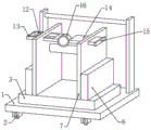
Fig. 1 is a schematic view of a communication structure of a power cable take-up and pay-off device.
Fig. 2 is a front view of a power cable take-up device.
Fig. 3 is a top view of the power cable take-up and pay-off device.
Fig. 4 is an enlarged schematic view of a portion a in fig. 2.
Fig. 5 is an enlarged schematic view of the structure at B in fig. 2.
In the figure: 1-bottom plate, 2-truckle, 3-base, 4-first motor, 5-threaded rod, 6-baffle, 7-movable plate, 8-supporting plate, 9-second motor, 10-winding rod, 11-transmission rod, 12-incomplete gear, 13-movable frame, 14-sliding plate, 15-limiting plate, 16-guide ring, 17-fixed block, 18-pressing block, 19-roller, 20-spring, 21-sliding chute, 22-connecting block, 23-guiding block, 24-belt wheel and 25-belt.
Detailed Description
The technical solution of the present patent will be described in further detail with reference to the following embodiments.
Reference will now be made in detail to embodiments of the present patent, examples of which are illustrated in the accompanying drawings, wherein like or similar reference numerals refer to the same or similar elements or elements having the same or similar function throughout. The embodiments described below with reference to the drawings are exemplary only for the purpose of explaining the present patent and are not to be construed as limiting the present patent.
Example 1
Referring to fig. 1-3, in an embodiment of the present invention, a power cable take-up and pay-off device includes a bottom plate 1, a base 3 is fixedly connected to a top of the bottom plate 1, a take-up and pay-off mechanism is disposed on a top of the base 3, a lifting mechanism for a height of the take-up and pay-off mechanism is disposed inside the base 3, and a guide mechanism for tightening a cable is disposed on an upper side of the take-up and pay-off mechanism.
Example 2
In this embodiment, take-up and pay-off mechanism includes fly leaf 7, both ends upside, both sides are controlled in the setting of fly leaf 7 at base 3 be provided with wire winding pole 10 between the fly leaf 7, wire winding pole 10 is through setting up the drive at the left second motor 9 of left side fly leaf 7, second motor 9 bottom be provided with fly leaf 7 fixed connection's backup pad 8, backup pad 8 and second motor 9 bolted connection.
In this embodiment, the lifting mechanism includes a baffle 6 disposed outside the movable plate 7, the baffle 6 is fixedly connected with the base 3, the inner side of one end of the baffle 6 close to the movable plate 7 is provided with a sliding chute 21, the inner side of the sliding chute 21 is provided with a threaded rod 5, the bottom end of the threaded rod 5 is connected with the base 3 through a bearing, a first motor 4 which is connected with the base 3 through a bolt is arranged between the threaded rods 5 at two sides, belt wheels 24 are fixedly connected on the output end of the first motor 4 and the threaded rods 5 at the two sides, the belt wheels 24 are connected through a belt 25, the threaded rod 5 is provided with a connecting block 22 in a threaded connection mode on the outer side of the inner side portion of the sliding groove 21, the connecting block 22 is fixedly connected with the movable plate 7, and through the arrangement of a lifting mechanism, the distance between wire winding rod 10 and base 3 can be adjusted, the single pay-off capacity of wire winding rod 10 is improved, and the work efficiency is improved.
In this embodiment, the front and rear sides of the connecting block 22 are both fixedly connected with the guide block 23, and the inner side of the baffle 6 is provided with a guide groove slidably connected with the guide block 23.
In this embodiment, guiding mechanism includes slide 14, slide 14 sets up the upside at wire winding pole 10, slide 14 and fly leaf 7 sliding connection, fixed connection is provided with guide ring 16 on the slide 14, fixed connection is provided with a plurality of fixed blocks 17 on the lateral wall in the guide ring 16, the inboard sliding connection of fixed block 17 is provided with briquetting 18, fixed connection is provided with spring 20 between briquetting 18 and the fixed block 17, it is provided with gyro wheel 19 to articulate on the other end of briquetting 18, be connected through drive mechanism between slide 14 and the second motor 9, through setting up guiding mechanism, utilize briquetting 18 and spring 20, can be walked around the journey at the cable, provide certain resistance to the cable to make the cable tighten up, guarantee wire-wound validity.
In this embodiment, the right side of the sliding plate 14 is fixedly connected with a limiting plate 15.
In this embodiment, the transmission mechanism includes a transmission rod 11, the transmission rod 11 is disposed on the upper side of the winding rod 10, the transmission rod 11 is meshed with the winding rod 10 through a bevel gear, a support block fixedly connected with the movable plate 7 is disposed on the outer side of the transmission rod 11, the transmission rod 11 is connected with a support block bearing, an incomplete gear 12 is fixedly connected to the top of the transmission rod 11, a movable frame 13 fixedly connected with a sliding plate 14 is disposed on the outer side of the incomplete gear 12, teeth are disposed on the frame walls of the front side and the rear side inside the movable frame 13, and the guide ring 16 can be made to move left and right repeatedly by the transmission mechanism, so that cables wound on the winding rod 10 are orderly.
In this embodiment, bolted connection is provided with a plurality of truckles 2 bottom the bottom plate 1, through setting up truckles 2, makes things convenient for the removal of device.
This power cable take-up and pay-off device, through setting up elevating system, can adjust the distance between wire winding pole 10 and the base 3, improve the single unwrapping wire volume of wire winding pole 10, improve work efficiency, through setting up guiding mechanism, utilize briquetting 18 and spring 20, can be walked around the in-process at the cable, provide certain resistance to the cable, thereby make the cable tighten up, guarantee wire-wound validity, through setting up drive mechanism, can make the guide ring 16 advance about the repetitive motion, thereby the cable that makes around on wire winding pole 10 is neat orderly.
The working principle of the invention is as follows: one end of a cable penetrates through the guide ring 16 and is fixed at one end of the winding rod 10, the first grade 4 is started, the first motor 4 drives the threaded rod 5 to rotate through the belt wheel 24 and the belt 25, the threaded rod 5 drives the connecting block 22 to move upwards along the guide groove, so that the distance between the winding rod 10 and the base 3 is adjusted, the single unwinding amount of the winding rod 10 is improved, the working efficiency is improved, the second motor 9 is started, the second motor 9 drives the winding rod 10 to rotate for winding, meanwhile, the transmission rod 11 is driven to rotate, the transmission rod 11 drives the movable frame 13 to do left-right repeated motion through the incomplete gear 12 at the top, the guide ring 16 on the sliding plate 14 drives the cable to uniformly wind on the winding rod 10, meanwhile, the pressing block 18 and the spring 20 which are positioned on the inner side of the guide ring 16 can provide certain resistance to the cable in the process of winding, so that the cable, when the line is prevented, the second motor 9 is reversely rotated, and the cable is pulled at the same time, so that the cable can be taken out.
The above is only a preferred embodiment of the present invention, and it should be noted that, for those skilled in the art, it is possible to make several variations and modifications without departing from the concept of the present invention, and these should be considered as the protection scope of the present invention, which will not affect the effect of the implementation of the present invention and the utility of the patent.
Claims (7)
1. The utility model provides a power cable pay-off and take-up device, includes bottom plate (1), its characterized in that, bottom plate (1) top fixed connection is provided with base (3), base (3) top is provided with receipts paying out machine and constructs, base (3) inboard is provided with the elevating system who is used for receiving the height of paying out machine, receipts paying out machine constructs the upside and is provided with the guiding mechanism that makes the cable tighten up.
2. The power cable take-up and pay-off device as claimed in claim 1, wherein the take-up and pay-off mechanism comprises a movable plate (7), the movable plate (7) is arranged on the upper sides of the left and right ends of the base (3), a winding rod (10) is arranged between the movable plates (7) on two sides, the winding rod (10) is driven by a second motor (9) arranged on the left side of the movable plate (7) on the left side, a supporting plate (8) fixedly connected with the movable plate (7) is arranged at the bottom of the second motor (9), and the supporting plate (8) is connected with the second motor (9) through bolts.
3. The power cable take-up and pay-off device as claimed in claim 2, wherein the lifting mechanism comprises a baffle (6) arranged outside the movable plate (7), the baffle (6) is fixedly connected with the base (3), a chute (21) is arranged at the inner side of one end of the baffle (6) close to the movable plate (7), a threaded rod (5) is arranged at the inner side of the chute (21), the bottom end of the threaded rod (5) is connected with the base (3) through a bearing, a first motor (4) which is connected with the base (3) through a bolt is arranged between the threaded rods (5) at two sides, belt wheels (24) are fixedly connected to the output end of the first motor (4) and the threaded rods (5) at two sides, the belt wheels (24) are connected through a belt (25), and a connecting block (22) is arranged at the outer side part of the chute (21) of the threaded, the connecting block (22) is fixedly connected with the movable plate (7).
4. The power cable take-up and pay-off device according to claim 3, wherein the front side and the rear side of the connecting block (22) are fixedly connected with guide blocks (23), and the inner side of the baffle plate (6) is provided with a guide groove in sliding connection with the guide blocks (23).
5. The power cable take-up and pay-off device as claimed in claim 1, wherein the guiding mechanism comprises a sliding plate (14), the sliding plate (14) is arranged on the upper side of the winding rod (10), the sliding plate (14) is slidably connected with the movable plate (7), a guide ring (16) is fixedly connected with the sliding plate (14), a plurality of fixed blocks (17) are fixedly connected with the inner side ring wall of the guide ring (16), a pressing block (18) is slidably connected with the inner side of the fixed blocks (17), a spring (20) is fixedly connected between the pressing block (18) and the fixed blocks (17), a roller (19) is hinged to the other end of the pressing block (18), and the sliding plate (14) is connected with the second motor (9) through a transmission mechanism.
6. A power cable take-up and pay-off device according to claim 5, wherein a limiting plate (15) is fixedly connected to the right side of the sliding plate (14).
7. The power cable take-up and pay-off device as claimed in claim 6, wherein the transmission mechanism comprises a transmission rod (11), the transmission rod (11) is arranged on the upper side of the winding rod (10), the transmission rod (11) is meshed with the winding rod (10) through a bevel gear, a supporting block fixedly connected with the movable plate (7) is arranged on the outer side of the transmission rod (11), the transmission rod (11) is connected with a supporting block bearing, an incomplete gear (12) is fixedly connected to the top of the transmission rod (11), a movable frame (13) fixedly connected with the sliding plate (14) is arranged on the outer side of the incomplete gear (12), and teeth are arranged on the frame walls on the front side and the rear side inside the movable frame (13).
Priority Applications (1)
| Application Number | Priority Date | Filing Date | Title |
|---|---|---|---|
| CN201911284245.0A CN110902502A (en) | 2019-12-13 | 2019-12-13 | Power cable take-up and pay-off device |
Applications Claiming Priority (1)
| Application Number | Priority Date | Filing Date | Title |
|---|---|---|---|
| CN201911284245.0A CN110902502A (en) | 2019-12-13 | 2019-12-13 | Power cable take-up and pay-off device |
Publications (1)
| Publication Number | Publication Date |
|---|---|
| CN110902502A true CN110902502A (en) | 2020-03-24 |
Family
ID=69824435
Family Applications (1)
| Application Number | Title | Priority Date | Filing Date |
|---|---|---|---|
| CN201911284245.0A Pending CN110902502A (en) | 2019-12-13 | 2019-12-13 | Power cable take-up and pay-off device |
Country Status (1)
| Country | Link |
|---|---|
| CN (1) | CN110902502A (en) |
Cited By (1)
| Publication number | Priority date | Publication date | Assignee | Title |
|---|---|---|---|---|
| CN114057040A (en) * | 2021-11-15 | 2022-02-18 | 贵州电网有限责任公司 | Supplementary storage disc of exploration cable shaft |
Citations (12)
| Publication number | Priority date | Publication date | Assignee | Title |
|---|---|---|---|---|
| KR101545927B1 (en) * | 2014-02-05 | 2015-08-20 | 한국원자력연구원 | Winding machine for controling tension and pipeline inspection robot having the same |
| CN205419301U (en) * | 2016-02-03 | 2016-08-03 | 清远市瑞鑫再生物资有限公司 | Traditional thread binding putting is sent in lap guard |
| CN205602825U (en) * | 2016-05-04 | 2016-09-28 | 重庆港乾机械有限公司 | Not intact wheeled spooler of full -tooth |
| CN107298350A (en) * | 2017-07-24 | 2017-10-27 | 成都菲斯普科技有限公司 | A kind of cable reel device |
| CN207434736U (en) * | 2017-10-19 | 2018-06-01 | 薛懂伟 | A kind of fully-automatic spooling machine |
| CN108163642A (en) * | 2017-11-22 | 2018-06-15 | 国网江苏省电力公司兴化市供电公司 | A kind of power construction drawing cable line apparatus |
| CN108910600A (en) * | 2018-06-08 | 2018-11-30 | 佛山新籁工程科技有限公司 | A kind of power cable actinobacillus device of anti-random line |
| CN208631847U (en) * | 2018-06-29 | 2019-03-22 | 德京集团股份有限公司 | A kind of power construction cable unwinding device |
| CN208700270U (en) * | 2018-07-25 | 2019-04-05 | 重庆永富电线电缆有限公司 | Up- coiler |
| CN208761874U (en) * | 2018-08-22 | 2019-04-19 | 山东云鼎智慧农业装备有限公司 | A kind of fine-spraying belt winding ancillary equipment manually |
| CN208980089U (en) * | 2018-09-28 | 2019-06-14 | 高邮市鼎天高分子材料有限公司 | A kind of cable processing automatic deploying and retracting line machine |
| CN209210098U (en) * | 2018-11-02 | 2019-08-06 | 宝胜(宁夏)线缆科技有限公司 | A kind of take-up and pay-off device of cable |
-
2019
- 2019-12-13 CN CN201911284245.0A patent/CN110902502A/en active Pending
Patent Citations (12)
| Publication number | Priority date | Publication date | Assignee | Title |
|---|---|---|---|---|
| KR101545927B1 (en) * | 2014-02-05 | 2015-08-20 | 한국원자력연구원 | Winding machine for controling tension and pipeline inspection robot having the same |
| CN205419301U (en) * | 2016-02-03 | 2016-08-03 | 清远市瑞鑫再生物资有限公司 | Traditional thread binding putting is sent in lap guard |
| CN205602825U (en) * | 2016-05-04 | 2016-09-28 | 重庆港乾机械有限公司 | Not intact wheeled spooler of full -tooth |
| CN107298350A (en) * | 2017-07-24 | 2017-10-27 | 成都菲斯普科技有限公司 | A kind of cable reel device |
| CN207434736U (en) * | 2017-10-19 | 2018-06-01 | 薛懂伟 | A kind of fully-automatic spooling machine |
| CN108163642A (en) * | 2017-11-22 | 2018-06-15 | 国网江苏省电力公司兴化市供电公司 | A kind of power construction drawing cable line apparatus |
| CN108910600A (en) * | 2018-06-08 | 2018-11-30 | 佛山新籁工程科技有限公司 | A kind of power cable actinobacillus device of anti-random line |
| CN208631847U (en) * | 2018-06-29 | 2019-03-22 | 德京集团股份有限公司 | A kind of power construction cable unwinding device |
| CN208700270U (en) * | 2018-07-25 | 2019-04-05 | 重庆永富电线电缆有限公司 | Up- coiler |
| CN208761874U (en) * | 2018-08-22 | 2019-04-19 | 山东云鼎智慧农业装备有限公司 | A kind of fine-spraying belt winding ancillary equipment manually |
| CN208980089U (en) * | 2018-09-28 | 2019-06-14 | 高邮市鼎天高分子材料有限公司 | A kind of cable processing automatic deploying and retracting line machine |
| CN209210098U (en) * | 2018-11-02 | 2019-08-06 | 宝胜(宁夏)线缆科技有限公司 | A kind of take-up and pay-off device of cable |
Cited By (2)
| Publication number | Priority date | Publication date | Assignee | Title |
|---|---|---|---|---|
| CN114057040A (en) * | 2021-11-15 | 2022-02-18 | 贵州电网有限责任公司 | Supplementary storage disc of exploration cable shaft |
| CN114057040B (en) * | 2021-11-15 | 2023-11-03 | 贵州电网有限责任公司 | Auxiliary storage disc for detection cable well |
Similar Documents
| Publication | Publication Date | Title |
|---|---|---|
| CN211110391U (en) | Wire rope is with receiving and releasing device for elevator | |
| CN2271516Y (en) | Electrical cable winding appts | |
| CN209758751U (en) | Cable winding and unwinding devices that transformer substation engineering construction was used | |
| CN104743413A (en) | Manual wire payoff and takeup device | |
| CN111099451A (en) | Electric winder for unmanned submersible | |
| CN110902502A (en) | Power cable take-up and pay-off device | |
| CN115693504A (en) | Construction equipment is laid to transformer substation's high-tension line | |
| CN204967138U (en) | Portable aerial [insulated] cable lays auxiliary device | |
| CN109592512B (en) | Cable is accomodate arrangement and is wrapped up in attaches device | |
| CN219173921U (en) | Cable laying device with cable protect function for highway construction | |
| CN210866981U (en) | Power line tension device for power line paying-off | |
| CN202633831U (en) | Manual multifunctional wire tensioning device | |
| CN216997022U (en) | Wire coiling and paying-off device capable of preventing wire disorder | |
| CN213770838U (en) | Communication cable winding and unwinding devices for communication engineering | |
| CN215516109U (en) | Multifunctional cable laying device | |
| CN209922654U (en) | Can receive and release detachable device of electric wire | |
| CN112071509B (en) | Adjustable wire bundling machine for cable production | |
| CN113336006A (en) | Take-up device for electric power construction | |
| CN212100612U (en) | Counterweight type driving box | |
| CN210505334U (en) | Hybrid power's quick hank grinds machine | |
| CN210480481U (en) | Be used for supply cable adjusting device that relaxes | |
| CN217808420U (en) | Quick splicing type electrical equipment hoisting device for transformer substation | |
| CN215119878U (en) | Cable bundling device | |
| CN105502077A (en) | Traction frame | |
| CN110759175A (en) | Cable coiling mechanism for communication engineering |
Legal Events
| Date | Code | Title | Description |
|---|---|---|---|
| PB01 | Publication | ||
| PB01 | Publication | ||
| SE01 | Entry into force of request for substantive examination | ||
| SE01 | Entry into force of request for substantive examination | ||
| RJ01 | Rejection of invention patent application after publication |
Application publication date: 20200324 |
|
| RJ01 | Rejection of invention patent application after publication |