CN110900100B - Be used for cylindric part welded supplementary welding set - Google Patents

Be used for cylindric part welded supplementary welding set Download PDF

Info

Publication number
CN110900100B
CN110900100B CN201911230860.3A CN201911230860A CN110900100B CN 110900100 B CN110900100 B CN 110900100B CN 201911230860 A CN201911230860 A CN 201911230860A CN 110900100 B CN110900100 B CN 110900100B
Authority
CN
China
Prior art keywords
rotating
welding
fixedly connected
shaped base
cross
Prior art date
Legal status (The legal status is an assumption and is not a legal conclusion. Google has not performed a legal analysis and makes no representation as to the accuracy of the status listed.)
Active
Application number
CN201911230860.3A
Other languages
Chinese (zh)
Other versions
CN110900100A (en
Inventor
刘忠辉
Current Assignee (The listed assignees may be inaccurate. Google has not performed a legal analysis and makes no representation or warranty as to the accuracy of the list.)
Shandong Lijiali Steel Structure Co ltd
Original Assignee
Huaibei Lianlian Information Technology Co ltd
Priority date (The priority date is an assumption and is not a legal conclusion. Google has not performed a legal analysis and makes no representation as to the accuracy of the date listed.)
Filing date
Publication date
Application filed by Huaibei Lianlian Information Technology Co ltd filed Critical Huaibei Lianlian Information Technology Co ltd
Priority to CN201911230860.3A priority Critical patent/CN110900100B/en
Publication of CN110900100A publication Critical patent/CN110900100A/en
Application granted granted Critical
Publication of CN110900100B publication Critical patent/CN110900100B/en
Active legal-status Critical Current
Anticipated expiration legal-status Critical

Links

Images

Classifications

    • B—PERFORMING OPERATIONS; TRANSPORTING
    • B23—MACHINE TOOLS; METAL-WORKING NOT OTHERWISE PROVIDED FOR
    • B23K—SOLDERING OR UNSOLDERING; WELDING; CLADDING OR PLATING BY SOLDERING OR WELDING; CUTTING BY APPLYING HEAT LOCALLY, e.g. FLAME CUTTING; WORKING BY LASER BEAM
    • B23K37/00—Auxiliary devices or processes, not specially adapted for a procedure covered by only one of the other main groups of this subclass
    • B23K37/04—Auxiliary devices or processes, not specially adapted for a procedure covered by only one of the other main groups of this subclass for holding or positioning work
    • B23K37/053—Auxiliary devices or processes, not specially adapted for a procedure covered by only one of the other main groups of this subclass for holding or positioning work aligning cylindrical work; Clamping devices therefor
    • B—PERFORMING OPERATIONS; TRANSPORTING
    • B23—MACHINE TOOLS; METAL-WORKING NOT OTHERWISE PROVIDED FOR
    • B23K—SOLDERING OR UNSOLDERING; WELDING; CLADDING OR PLATING BY SOLDERING OR WELDING; CUTTING BY APPLYING HEAT LOCALLY, e.g. FLAME CUTTING; WORKING BY LASER BEAM
    • B23K37/00—Auxiliary devices or processes, not specially adapted for a procedure covered by only one of the other main groups of this subclass
    • B—PERFORMING OPERATIONS; TRANSPORTING
    • B23—MACHINE TOOLS; METAL-WORKING NOT OTHERWISE PROVIDED FOR
    • B23K—SOLDERING OR UNSOLDERING; WELDING; CLADDING OR PLATING BY SOLDERING OR WELDING; CUTTING BY APPLYING HEAT LOCALLY, e.g. FLAME CUTTING; WORKING BY LASER BEAM
    • B23K2101/00—Articles made by soldering, welding or cutting
    • B23K2101/04—Tubular or hollow articles

Landscapes

  • Physics & Mathematics (AREA)
  • Optics & Photonics (AREA)
  • Engineering & Computer Science (AREA)
  • Mechanical Engineering (AREA)
  • Butt Welding And Welding Of Specific Article (AREA)

Abstract

The invention discloses an auxiliary welding device for welding cylindrical parts, which comprises a cross-shaped base and a rotating device arranged at one end of the cross-shaped base; the auxiliary welding device for welding the cylindrical parts further comprises an adjusting device arranged at the other end of the cross-shaped base and a deslagging device arranged on the side surface of the adjusting device, the circular parts can be automatically welded under the action of the rotating device, the angle of the welding gun can be adjusted during welding under the action of the adjusting device, and equipment can be deslagged under the action of the deslagging device; the side surface of the cross-shaped base is provided with a controller, the controller is fixedly connected with the cross-shaped base, the four corners of the lower surface of the cross-shaped base are provided with rectangular bases, and the rectangular bases are fixedly connected with the cross-shaped base. The invention has the advantages of simple structure and strong practicability.

Description

Be used for cylindric part welded supplementary welding set
Technical Field
The invention relates to the field of auxiliary welding, in particular to an auxiliary welding device for welding cylindrical parts.
Background
The round pipe is an important structural component and is widely applied to various steel frame structures. The connection between the pipe mainly adopts modes such as spiro union, welding and cup joint, and wherein the welding is because firm in connection, and is little to pleasing to the eye influence, consequently extensive being applied to in the pipe is connected. But welding between the pipe also has the congenital difficulty, because the particularity on pipe surface leads to the intersecting line between the pipe comparatively complicated, has also led to when the pipe welding to ensure that the intersecting line between the pipe of both ends coincides completely has certain degree of difficulty simultaneously, therefore often needs many people to cooperate when welding the pipe by hand and just can go on, even so welded yields is also not high, has caused a large amount of wastes of material. If the novel fixing device can effectively fix two sections of circular tubes with different diameters, lengths and welding angles, so that intersecting lines of the two sections of circular tubes can be completely overlapped, welding precision is guaranteed, the problems can be effectively solved by the novel fixing device which can be operated by one person, and the adjustable fixing device for circular tube welding is provided.
Disclosure of Invention
The invention aims to solve the problems and designs an auxiliary welding device for welding cylindrical parts.
The technical scheme of the invention is that the device comprises a cross-shaped base and a rotating device arranged at one end of the cross-shaped base; the auxiliary welding device for welding the cylindrical parts further comprises an adjusting device arranged at the other end of the cross-shaped base and a deslagging device arranged on the side surface of the adjusting device, the circular parts can be automatically welded under the action of the rotating device, the angle of the welding gun can be adjusted during welding under the action of the adjusting device, and equipment can be deslagged under the action of the deslagging device; the side surface of the cross-shaped base is provided with a controller, the controller is fixedly connected with the cross-shaped base, the four corners of the lower surface of the cross-shaped base are provided with rectangular bases, and the rectangular bases are fixedly connected with the cross-shaped base.
The rotating device comprises a fixed shaft arranged at two ends of the upper surface of the cross-shaped base, the fixed shaft is fixedly connected with the cross-shaped base, the upper end of the fixed shaft is provided with a first bearing, the first bearing is connected with the fixed shaft in a cartridge manner, the outer surface of the first bearing is provided with a rotating table, the rotating table is fixedly connected with the first bearing, the outer surface of the rotating table is provided with a first toothed ring, the first toothed ring is fixedly connected with the rotating table, two ends of the cross-shaped base are provided with a first rotating motor, and the first rotating motor is fixedly connected with the cross-shaped base. A first gear meshed with the first gear ring is arranged at the rotating end of the rotating motor, a first groove is formed in the upper surface of the rotating platform, two first grooves are parallel to each other, first electronic sliding blocks are arranged at two ends of each first groove and are in sliding connection with the first grooves, an electronic roller is arranged in the center of the upper surface of each first electronic sliding block and is connected with the first electronic sliding blocks in an inserting mode; the side surface of the rotating platform is provided with a first linear motor, the lower end of the first linear motor is fixedly connected with the rotating platform, the telescopic end of the first linear motor is provided with a first connecting rod, one end of the first connecting rod is fixedly connected with the first linear motor, the lower surface of the connecting rod is provided with a second linear motor, the upper end of the second linear motor is fixedly connected with the first connecting rod, the lower end of the second linear motor is fixedly connected with the first linear motor, one end of the first connecting rod is provided with an auxiliary roller wheel, and the auxiliary roller wheel is fixedly connected with the first connecting rod; the rotation through the revolving stage can make the welding piece carry out the regulation of certain angle, and the slip through electronic sliding block one can make the pipe of equipment adaptation different models weld.
The adjusting device comprises a first sliding groove arranged in the center of the upper surface of the cross-shaped base, and the first sliding groove is fixedly connected with the cross-shaped base; the extending direction of the first sliding chute is perpendicular to the direction of a connecting line between the fixed shafts, the inner surface of the first sliding chute is provided with an electronic sliding block II, the electronic sliding block II is connected with the first sliding chute in a sliding manner, the upper surface of the electronic sliding block II is provided with an electronic telescopic rod, the upper end of the electronic telescopic rod is provided with a mounting box I, the mounting box I is fixedly connected with the electronic telescopic rod, one side surface of the mounting box is provided with a rectangular through hole, the rectangular through hole is fixedly connected with the mounting box I, the inner surface of the rectangular through hole is provided with a rectangular sliding rod, the lower surface of the rectangular sliding rod is provided with a rack I, the rack I is fixedly connected with the rectangular sliding rod, one side surface of the mounting box is provided with a rotating motor II, the rotating end of the rotating motor II is provided with a gear II meshed with the rack I, one end of the rectangular sliding rod is provided with a progressive motor I, the rotating end of the progressive motor I is provided with a welding frame, the welding frame is connected with the progressive motor I in an inserting manner, and the side surface of the welding frame is provided with a linear motor III, and one end of the linear motor is fixedly connected with the first progressive motor.
The deslagging device comprises a linear motor IV arranged on the lower surface of the rectangular sliding rod, the upper end of the linear motor IV is fixedly connected with the rectangular sliding rod, the four telescopic ends of the linear motor are provided with a mounting box II, the lower end of the mounting box II is provided with a sliding groove II, the sliding groove II is fixedly connected with the mounting box II, the inner surface of the sliding groove II is provided with a sliding block, the lower end of the sliding block is provided with an impact block, the impact block is fixedly connected with the sliding block, two side surfaces of the mounting box are provided with a rotating motor III, the rotating end of the rotating motor III is provided with a rotating sheet, the side surface of the rotating sheet is provided with a pin shaft, the outer surface of the pin shaft is provided with a connecting rod II, the upper end of the connecting rod II is connected with the pin shaft in a plug-in manner, and the lower end of the connecting rod II is connected with the sliding block in a plug-in manner.
And a first inductor is arranged at the lower end of the second mounting box.
And a second inductor is arranged at the lower end of the welding frame.
And a third inductor is arranged on the side surface of the auxiliary roller.
And an anti-skid layer is arranged on the outer surface of the electronic roller.
The auxiliary welding device for welding the cylindrical parts, which is manufactured by the technical scheme of the invention, can automatically weld the cylindrical parts through the action of the rotating device, thereby improving the working efficiency. The angle of the welding gun can be adjusted by the adjusting device during welding, so that the welding gun can adapt to the change of the working environment. Can make equipment carry out the slagging-off through dross removal mechanism's effect to improve equipment's automation.
Drawings
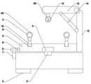
FIG. 1 is a schematic structural diagram of an auxiliary welding device for welding cylindrical parts according to the present invention;
FIG. 2 is a schematic view of a rotary apparatus of the present invention;
FIG. 3 is a schematic view of the adjustment device of the present invention;
FIG. 4 is a schematic view of the deslagging apparatus of the present invention;
in the figure, 1, a cross-shaped base; 2. a controller; 3. a rectangular base; 4. a first bearing; 5. a rotating table; 6. a first toothed ring; 7. a first rotating motor; 8. a first gear; 9. a first groove; 10. a first electronic slider; 11. an electronic roller; 12. a linear motor I; 13. a first connecting rod; 14. a linear motor II; 15. an auxiliary roller; 16. a first sliding chute; 17. a fixed shaft; 18. a second electronic slider; 19. an electronic telescoping rod; 20. mounting a first box; 21. a rectangular through hole; 22. a rectangular slide bar; 23. a first rack; 24. a second rotating motor; 25. a second gear; 26. a first progress motor; 27. a linear motor III; 28. a linear motor IV; 29. mounting a second box; 30. a second chute; 31. a slider; 32. an impact block; 33. a third rotating motor; 34. a rotating sheet; 35. a pin shaft; 36. a second connecting rod; 37. a first inductor; 38. a second inductor; 39. a third inductor; 40. and an anti-slip layer.
Detailed Description
The invention is described in detail below with reference to the drawings, as shown in fig. 1-4.
In the embodiment, the circular parts can be automatically welded through the action of the rotating device, so that the working efficiency is improved. The angle of the welding gun can be adjusted by the adjusting device during welding, so that the welding gun can adapt to the change of the working environment. Can make equipment carry out the slagging-off through dross removal mechanism's effect to improve equipment's automation.
First step, when needs welding, at first put the pipe that needs the welding respectively in electron running roller 11 top, because 5 upper surfaces of revolving stage are equipped with four symmetry electron running rollers 11, so the pipe can be stable in electron running roller 11 top, controller 2 control electron running roller 11 rotates in the welding, electron running roller 11 directly drives the pipe and rotates, later controller 2 control linear electric motor one 12, linear electric motor two 14 carry out the work of mutually supporting, make the outer surface contact of auxiliary running roller 15 to the upper end of pipe, auxiliary running roller 15 is in triangular summit with electron running roller 11, fix the pipe better.
Second step, when the pipe is rotatory, controller 2 control electron telescopic link 19 carries out appropriate flexible, mounting box 20 is along with removing, directly drive gear two 25 when rotating motor two 24 rotates and rotate, gear two 25 directly drives rectangle slide bar 22 and slides, welded angle can be adjusted in the rotation of controller 2 control progress motor 26, when the welding slag needs to be cleared up, controller 2 control rotating motor three 33 rotates, the indirect drive impact block 32 of rotating motor three 33 rotation end is the piston motion, and beat the welding slag to the pipe surface, thereby realize the purpose of automatic clearance welding slag.
And thirdly, the controller 2 controls the rotation of the first rotating motor 7 to directly drive the first gear 8 to rotate, and the rotation of the first gear 8 indirectly drives the rotating platform 5 to rotate, so that the purpose of adjusting the welding angle is achieved.
The technical solutions described above only represent the preferred technical solutions of the present invention, and some possible modifications to some parts of the technical solutions by those skilled in the art all represent the principles of the present invention, and fall within the protection scope of the present invention.

Claims (6)

1. An auxiliary welding device for welding cylindrical parts comprises a cross-shaped base (1) and a rotating device arranged at one end of the cross-shaped base (1); the auxiliary welding device for welding the cylindrical parts is characterized by further comprising an adjusting device arranged at the other end of the cross-shaped base (1) and a deslagging device arranged on the side surface of the adjusting device, wherein the circular parts can be automatically welded under the action of the rotating device, a welding gun can be subjected to angle adjustment during welding under the action of the adjusting device, and equipment can be subjected to deslagging under the action of the deslagging device; the side surface of the cross-shaped base (1) is provided with a controller (2), the controller (2) is fixedly connected with the cross-shaped base (1), the four corners of the lower surface of the cross-shaped base (1) are provided with rectangular bases (3), and the rectangular bases (3) are fixedly connected with the cross-shaped base (1);
the rotating device comprises fixed shafts (17) arranged at two ends of the upper surface of a cross-shaped base (1), the fixed shafts (17) are fixedly connected with the cross-shaped base (1), the upper ends of the fixed shafts (17) are provided with first bearings (4), the first bearings (4) are connected with the fixed shafts (17) in a plug-in manner, the outer surfaces of the first bearings (4) are provided with rotating tables (5), the rotating tables (5) are fixedly connected with the first bearings (4), the outer surfaces of the rotating tables (5) are fully provided with first gear rings (6), the first gear rings (6) are fixedly connected with the rotating tables (5), two ends of the cross-shaped base (1) are provided with first rotating motors (7), the first rotating motors (7) are fixedly connected with the cross-shaped base (1), the rotating ends of the first rotating motors (7) are provided with first gears (8) mutually meshed with the first gear rings (6), the upper surface of the rotating tables (5) is provided with first grooves (9), and the first grooves (9) are arranged in parallel with each other, two ends of the first groove (9) are provided with a first electronic sliding block (10), the first electronic sliding block (10) is in sliding connection with the first groove (9), an electronic roller (11) is arranged at the center of the upper surface of the first electronic sliding block (10), and the electronic roller (11) is connected with the first electronic sliding block (10) in an inserted manner; the side surface of the rotating platform (5) is provided with a linear motor I (12), the lower end of the linear motor I (12) is fixedly connected with the rotating platform (5), the telescopic end of the linear motor I (12) is provided with a connecting rod I (13), one end of the connecting rod I (13) is fixedly connected with the linear motor I (12), the lower surface of the connecting rod I (13) is provided with a linear motor II (14), the upper end of the linear motor II (14) is fixedly connected with the connecting rod I (13), the lower end of the linear motor II (14) is fixedly connected with the linear motor I (12), one end of the connecting rod I (13) is provided with an auxiliary roller (15), and the auxiliary roller (15) is fixedly connected with the connecting rod I (13); the rotating table (5) rotates to enable the welding part to be adjusted at a certain angle, and the electronic sliding block I (10) slides to enable the equipment to adapt to circular pipes of different models for welding;
the adjusting device comprises a first sliding groove (16) arranged in the center of the upper surface of the cross-shaped base (1), and the first sliding groove (16) is fixedly connected with the cross-shaped base (1); the extending direction of the first sliding groove (16) is perpendicular to the direction of a connecting line between the fixed shafts (17), the inner surface of the first sliding groove (16) is provided with a second electronic sliding block (18), the second electronic sliding block (18) is in sliding connection with the first sliding groove (16), the upper surface of the second electronic sliding block (18) is provided with an electronic telescopic rod (19), the upper end of the electronic telescopic rod (19) is provided with a first mounting box (20), the first mounting box (20) is fixedly connected with the electronic telescopic rod (19), the side surface of the first mounting box (20) is provided with a rectangular through hole (21), the rectangular through hole (21) is fixedly connected with the first mounting box (20), the inner surface of the rectangular through hole (21) is provided with a rectangular sliding rod (22), the lower surface of the rectangular sliding rod (22) is provided with a first rack (23), the first rack (23) is fixedly connected with the rectangular sliding rod (22), the side surface of the first mounting box (20) is provided with a second rotating motor (24), a second gear (25) meshed with the first rack (23) is arranged at the rotating end of the second rotating motor (24), a first step motor (26) is arranged at one end of the rectangular sliding rod (22), a welding frame is arranged at the rotating end of the first step motor (26), the welding frame is connected with the first step motor (26) in a plug-in mode, a third linear motor (27) is arranged on the side surface of the welding frame, and one end of the third linear motor (27) is fixedly connected with the first step motor (26).
2. The auxiliary welding device for welding cylindrical parts according to claim 1, wherein the deslagging device comprises a fourth linear motor (28) disposed on the lower surface of the rectangular sliding rod (22), the upper end of the fourth linear motor (28) is fixedly connected with the rectangular sliding rod (22), the telescopic end of the fourth linear motor (28) is provided with a second mounting box (29), the lower end of the second mounting box (29) is provided with a second sliding chute (30), the second sliding chute (30) is fixedly connected with the second mounting box (29), the inner surface of the second sliding chute (30) is provided with a sliding block (31), the lower end of the sliding block (31) is provided with an impact block (32), the impact block (32) is fixedly connected with the sliding block (31), the side surface of the second mounting box (29) is provided with a third rotating motor (33), the rotating end of the third rotating motor (33) is provided with a rotating sheet (34), the side surface of the rotating sheet (34) is provided with a pin shaft (35), the outer surface of the pin shaft (35) is provided with a second connecting rod (36), the upper end of the second connecting rod (36) is connected with the pin shaft (35) in a plug-in manner, and the lower end of the second connecting rod (36) is connected with the sliding block (31) in a plug-in manner.
3. Auxiliary welding device for welding cylindrical parts according to claim 2, characterized in that the lower end of the second mounting box (29) is provided with a first inductor (37).
4. Auxiliary welding device for welding cylindrical parts according to claim 1, characterized in that the lower end of said welding frame is provided with a second inductor (38).
5. Auxiliary welding device for the welding of cylindrical parts, according to claim 1, characterized in that the side surface of said auxiliary roller (15) is provided with inductor three (39).
6. Auxiliary welding device for welding cylindrical parts according to claim 1, characterized in that the outer surface of the electronic roller (11) is provided with an anti-slip layer (40).
CN201911230860.3A 2019-12-05 2019-12-05 Be used for cylindric part welded supplementary welding set Active CN110900100B (en)

Priority Applications (1)

Application Number Priority Date Filing Date Title
CN201911230860.3A CN110900100B (en) 2019-12-05 2019-12-05 Be used for cylindric part welded supplementary welding set

Applications Claiming Priority (1)

Application Number Priority Date Filing Date Title
CN201911230860.3A CN110900100B (en) 2019-12-05 2019-12-05 Be used for cylindric part welded supplementary welding set

Publications (2)

Publication Number Publication Date
CN110900100A CN110900100A (en) 2020-03-24
CN110900100B true CN110900100B (en) 2021-10-15

Family

ID=69822463

Family Applications (1)

Application Number Title Priority Date Filing Date
CN201911230860.3A Active CN110900100B (en) 2019-12-05 2019-12-05 Be used for cylindric part welded supplementary welding set

Country Status (1)

Country Link
CN (1) CN110900100B (en)

Families Citing this family (1)

* Cited by examiner, † Cited by third party
Publication number Priority date Publication date Assignee Title
CN117226365A (en) * 2023-11-15 2023-12-15 哈尔滨兴胜机械有限公司 Welding auxiliary equipment for parts

Citations (6)

* Cited by examiner, † Cited by third party
Publication number Priority date Publication date Assignee Title
KR20090025909A (en) * 2007-09-07 2009-03-11 한성물류운반기계(주) Roller Mount of Flange Automatic Welding Machine with Magnet
CN204413491U (en) * 2015-01-09 2015-06-24 湖北龙星钢构有限公司 A kind of automatic welding machine with large circular duct butt-welding auxiliary mould
CN104942514A (en) * 2015-06-23 2015-09-30 苏州边桐传感科技有限公司 Welding and fixing rotary table
CN105344659A (en) * 2015-12-07 2016-02-24 浙江华仪电子股份有限公司 Workpiece surface cleaning device
CN108544143A (en) * 2018-04-18 2018-09-18 卢响锋 A kind of electronic component welding device
CN209078163U (en) * 2018-11-19 2019-07-09 乳山市创新新能源科技有限公司 A kind of fixed device of rotatable barrel soldering

Patent Citations (6)

* Cited by examiner, † Cited by third party
Publication number Priority date Publication date Assignee Title
KR20090025909A (en) * 2007-09-07 2009-03-11 한성물류운반기계(주) Roller Mount of Flange Automatic Welding Machine with Magnet
CN204413491U (en) * 2015-01-09 2015-06-24 湖北龙星钢构有限公司 A kind of automatic welding machine with large circular duct butt-welding auxiliary mould
CN104942514A (en) * 2015-06-23 2015-09-30 苏州边桐传感科技有限公司 Welding and fixing rotary table
CN105344659A (en) * 2015-12-07 2016-02-24 浙江华仪电子股份有限公司 Workpiece surface cleaning device
CN108544143A (en) * 2018-04-18 2018-09-18 卢响锋 A kind of electronic component welding device
CN209078163U (en) * 2018-11-19 2019-07-09 乳山市创新新能源科技有限公司 A kind of fixed device of rotatable barrel soldering

Also Published As

Publication number Publication date
CN110900100A (en) 2020-03-24

Similar Documents

Publication Publication Date Title
CN105290692B (en) A kind of steel tube tower elevation plane flange deflection welding equipment
CN218657608U (en) Oppositely-arranged welding positioner with lifting and distance adjusting functions
CN107097033B (en) A kind of 90 ° of elbow internal wall built-up welding displacement devices
CN117086561B (en) Large-scale automatic welding turning device
CN217751410U (en) A robot of coming out of stove for industrial silicon field
CN102101211B (en) Multifunctional cradle roll type roller series automatic submerged arc welding machine
CN119589228A (en) Metal pipe welding device with adjustable clamping
CN205147700U (en) Steel pipe tower angle of elevation flat flange welding equipment that shifts
CN206912595U (en) A kind of 90 ° of elbow internal wall built-up welding displacement devices
CN109702582A (en) A glass chamfering machine
CN110900100A (en) Be used for cylindric part welded supplementary welding set
CN115870682A (en) Water collecting and distributing device welding device
CN218081257U (en) A rotary adjustable pipe welding machine
CN116787062A (en) A kind of metal hose seamless welding equipment and its process
CN210306173U (en) Circular seam submerged arc welding equipment in pressure vessel
CN105252105B (en) Flame groove cutting machine
CN204639523U (en) For the bracket system of mobile bus pipe
CN119501452A (en) Drill barrel rotary welding device
CN219443805U (en) High-precision welding device
CN217193471U (en) Welded pipe mill convenient for transferring welded pipe
CN115026387B (en) Semiautomatic welding equipment for gravure plate roller with shaft and clamping welding method thereof
CN117399444A (en) An automatic slab rotation device
CN109465487A (en) A kind of vertical steel tube cutting machine with equidistant directional cutting function
CN205437426U (en) flame groove cutting machine
CN107030151A (en) A kind of straight tube Bending Mould

Legal Events

Date Code Title Description
PB01 Publication
PB01 Publication
SE01 Entry into force of request for substantive examination
TA01 Transfer of patent application right

Effective date of registration: 20210927

Address after: 235000 building 6, entrepreneurship Park, new area, economic development zone, Huaibei City, Anhui Province

Applicant after: Huaibei Lianlian Information Technology Co.,Ltd.

Address before: 257400 science and Technology Information Service Center, 125 Liyi Road, Lijin County, Dongying City, Shandong Province

Applicant before: Liu Zhonghui

GR01 Patent grant
GR01 Patent grant
TR01 Transfer of patent right

Effective date of registration: 20221228

Address after: 272500 Government Station of Guocang Town, Wenshang County, Jining City, Shandong Province (intersection of National Highway 105 and Zhongxing Road)

Patentee after: Shandong lijiali Steel Structure Co.,Ltd.

Address before: 235000 building 6, entrepreneurship Park, new area, economic development zone, Huaibei City, Anhui Province

Patentee before: Huaibei Lianlian Information Technology Co.,Ltd.

PE01 Entry into force of the registration of the contract for pledge of patent right

Denomination of invention: An auxiliary welding device for welding cylindrical parts

Effective date of registration: 20230316

Granted publication date: 20211015

Pledgee: China Postal Savings Bank Limited by Share Ltd. Wenshang County sub branch

Pledgor: Shandong lijiali Steel Structure Co.,Ltd.

Registration number: Y2023980034934