CN110884940A - Stranding machine is with pay-off of conveniently changing coil - Google Patents
Stranding machine is with pay-off of conveniently changing coil Download PDFInfo
- Publication number
- CN110884940A CN110884940A CN201911035153.9A CN201911035153A CN110884940A CN 110884940 A CN110884940 A CN 110884940A CN 201911035153 A CN201911035153 A CN 201911035153A CN 110884940 A CN110884940 A CN 110884940A
- Authority
- CN
- China
- Prior art keywords
- fixedly connected
- pay
- rod
- support frame
- inner cavity
- Prior art date
- Legal status (The legal status is an assumption and is not a legal conclusion. Google has not performed a legal analysis and makes no representation as to the accuracy of the status listed.)
- Pending
Links
Images


Classifications
-
- B—PERFORMING OPERATIONS; TRANSPORTING
- B65—CONVEYING; PACKING; STORING; HANDLING THIN OR FILAMENTARY MATERIAL
- B65H—HANDLING THIN OR FILAMENTARY MATERIAL, e.g. SHEETS, WEBS, CABLES
- B65H49/00—Unwinding or paying-out filamentary material; Supporting, storing or transporting packages from which filamentary material is to be withdrawn or paid-out
- B65H49/18—Methods or apparatus in which packages rotate
- B65H49/20—Package-supporting devices
- B65H49/30—Swifts or skein holders
-
- B—PERFORMING OPERATIONS; TRANSPORTING
- B65—CONVEYING; PACKING; STORING; HANDLING THIN OR FILAMENTARY MATERIAL
- B65H—HANDLING THIN OR FILAMENTARY MATERIAL, e.g. SHEETS, WEBS, CABLES
- B65H49/00—Unwinding or paying-out filamentary material; Supporting, storing or transporting packages from which filamentary material is to be withdrawn or paid-out
- B65H49/18—Methods or apparatus in which packages rotate
- B65H49/34—Arrangements for effecting positive rotation of packages
-
- B—PERFORMING OPERATIONS; TRANSPORTING
- B65—CONVEYING; PACKING; STORING; HANDLING THIN OR FILAMENTARY MATERIAL
- B65H—HANDLING THIN OR FILAMENTARY MATERIAL, e.g. SHEETS, WEBS, CABLES
- B65H67/00—Replacing or removing cores, receptacles, or completed packages at paying-out, winding, or depositing stations
- B65H67/02—Arrangements for removing spent cores or receptacles and replacing by supply packages at paying-out stations
-
- D—TEXTILES; PAPER
- D07—ROPES; CABLES OTHER THAN ELECTRIC
- D07B—ROPES OR CABLES IN GENERAL
- D07B3/00—General-purpose machines or apparatus for producing twisted ropes or cables from component strands of the same or different material
-
- B—PERFORMING OPERATIONS; TRANSPORTING
- B65—CONVEYING; PACKING; STORING; HANDLING THIN OR FILAMENTARY MATERIAL
- B65H—HANDLING THIN OR FILAMENTARY MATERIAL, e.g. SHEETS, WEBS, CABLES
- B65H2701/00—Handled material; Storage means
- B65H2701/30—Handled filamentary material
- B65H2701/36—Wires
Landscapes
- Wire Processing (AREA)
Abstract
本发明公开了一种捻股机用方便更换线圈的放线装置,包括固定架,所述固定架顶部的左侧固定连接有第一支撑架,所述固定架顶部的右侧固定连接有第二支撑架,所述第一支撑架与第二支撑架之间活动连接有放线辊,所述第一支撑架的内腔固定连接有轴承。本发明通过固定架、第一支撑架、第二支撑架、放线辊、轴承、固定轴、螺纹套、连接杆、外壳、传动杆、从动齿轮、第一电机、转杆、主动齿轮、套管、弹簧、垫板、固定块、卡块、卡槽和箱体的配合使用,能够有效对传统捻股机的放线装置进行改进,在保持原有自转的基础上,扩大工字轮的适配范围,并做到拆卸和安装方便,减少人员搬运的使用,从而达到提高工作效率和产品质量的目的。
The invention discloses a wire pay-off device for a twisting machine which is convenient for replacing coils. Two support frames, a pay-off roller is movably connected between the first support frame and the second support frame, and a bearing is fixedly connected to the inner cavity of the first support frame. The invention adopts a fixed frame, a first support frame, a second support frame, a pay-off roller, a bearing, a fixed shaft, a threaded sleeve, a connecting rod, a casing, a transmission rod, a driven gear, a first motor, a rotating rod, a driving gear, The combined use of sleeves, springs, backing plates, fixing blocks, clamping blocks, clamping grooves and the box body can effectively improve the pay-off device of the traditional stranding machine, and expand the I-shaped wheel on the basis of maintaining the original rotation. It can be easily disassembled and installed, and reduce the use of personnel handling, so as to achieve the purpose of improving work efficiency and product quality.
Description
技术领域technical field
本发明涉及捻股机技术领域,具体为一种捻股机用方便更换线圈的放线装置。The invention relates to the technical field of twisting machines, in particular to a pay-off device for a twisting machine that can easily replace coils.
背景技术Background technique
捻股机是用于将若干金属丝按一定捻距和捻向绞拧成股的机器,捻股机按机体结构类型有筐篮式、管式和无管式等几种,其中管式捻股机由一节或数节筒体组成机体,载线工字轮在机体内沿中心呈一字形排列,工字轮放线时始终保持水平状态,筒体的高速旋转与牵引装置产生的直线牵引相配合,使钢丝产生螺旋线缠绕和股的直线运动,形成了具有一定捻距的股,从而完成了股的基本捻制动作,与筐篮式机相比,捻制原理相同,但结构却有显著改进,管式捻股机简体体积小,重心低,转动惯量小,运转速度快,噪声低,运转平稳,操作方便,适合大部分绳股,特别是线接触钢绳股和钢绞线的捻制。The twisting machine is a machine used to twist several metal wires into strands according to a certain laying distance and twisting direction. The stranding machine is composed of one or several cylinders. The wire-carrying I-spools are arranged in a line along the center of the body. The I-spools are always in a horizontal state when paying off the wire. The high-speed rotation of the cylinder and the straight line generated by the traction device With the combination of traction, the steel wire produces helical winding and linear movement of the strands, forming strands with a certain twist distance, thereby completing the basic twisting action of the strands. Compared with the basket type machine, the twisting principle is the same, but the structure However, there are significant improvements. The tubular stranding machine is small in size, low in center of gravity, small in moment of inertia, fast in operation, low in noise, stable in operation, and easy to operate. Twisting of threads.
传统捻股机的放线装置多采用穿杆式放线装置,先将轴杆安装在工字轮上,然后将工字轮采用人工搬运的方式进行安装,因人员不当的关系,极易造成工字轮损坏,同时因捻股机的放线装置多为固定结构,限制了工字轮安装使用的范围,必须在不同的放线装置上使用配套的工字轮。The pay-off device of the traditional twisting machine mostly adopts the rod-type pay-off device. The shaft is first installed on the I-shaped wheel, and then the I-shaped wheel is installed by manual handling. Due to improper personnel, it is very easy to cause The I-spool is damaged, and at the same time, the pay-off devices of the twisting machine are mostly fixed structures, which limits the range of installation and use of the I-spool. The matching I-spool must be used on different pay-off devices.
发明内容SUMMARY OF THE INVENTION
本发明的目的在于提供一种捻股机用方便更换线圈的放线装置,具备便于更换线圈的优点,解决了捻股机的放线装置多为固定结构,限制了工字轮安装使用的范围,必须在不同的放线装置上使用配套的工字轮的问题。The purpose of the present invention is to provide a pay-off device for a twisting machine that is convenient to replace the coil, which has the advantage of being easy to replace the coil, and solves that most of the pay-off device of the twisting machine is a fixed structure, which limits the installation and use range of the I-shaped wheel. , it is necessary to use matching spools on different pay-off devices.
为实现上述目的,本发明提供如下技术方案:一种捻股机用方便更换线圈的放线装置,包括固定架,所述固定架顶部的左侧固定连接有第一支撑架,所述固定架顶部的右侧固定连接有第二支撑架,所述第一支撑架与第二支撑架之间活动连接有放线辊,所述第一支撑架的内腔固定连接有轴承,所述轴承的内腔转动连接有固定轴,所述放线辊的左侧固定连接有螺纹套,所述螺纹套与固定轴的右侧螺纹连接,所述放线辊的右侧固定连接有连接杆,所述第二支撑架的右侧固定连接有外壳,所述外壳内腔右侧的顶部活动连接有传动杆,所述传动杆的表面固定连接有从动齿轮,所述外壳右侧的底部固定连接有第一电机,所述第一电机的输出端固定连接有转杆,所述转杆的左侧贯穿至外壳的内腔,所述转杆的表面固定连接有与从动齿轮配合使用的主动齿轮,所述传动杆的左侧贯穿外壳的内腔并延伸至第二支撑架的左侧,所述传动杆的左侧固定连接有套管,所述套管内腔的右侧固定连接有弹簧,所述弹簧的左侧固定连接有垫板,所述连接杆的右侧延伸至套管的内腔并与垫板接触,所述套管的顶部和底部均设置有固定块,两个固定块相对的一侧固定连接有卡块,所述卡块远离固定块的一侧延伸至套管的内腔,所述连接杆的顶部和底部均开设有与卡块配合使用的卡槽,所述固定架的底部固定连接有箱体。In order to achieve the above purpose, the present invention provides the following technical solutions: a pay-off device for a twisting machine that is convenient for replacing coils, comprising a fixing frame, a first support frame is fixedly connected to the left side of the top of the fixing frame, and the fixing frame is A second support frame is fixedly connected to the right side of the top, a pay-off roller is movably connected between the first support frame and the second support frame, and a bearing is fixedly connected to the inner cavity of the first support frame. The inner cavity is rotatably connected with a fixed shaft, the left side of the pay-off roller is fixedly connected with a threaded sleeve, the threaded sleeve is threadedly connected with the right side of the fixed shaft, and the right side of the pay-off roller is fixedly connected with a connecting rod, so The right side of the second support frame is fixedly connected with a casing, the top of the inner cavity of the casing is movably connected with a transmission rod, the surface of the transmission rod is fixedly connected with a driven gear, and the bottom of the right side of the casing is fixedly connected There is a first motor, the output end of the first motor is fixedly connected with a rotating rod, the left side of the rotating rod penetrates into the inner cavity of the casing, and the surface of the rotating rod is fixedly connected with a driving force used in cooperation with the driven gear. gear, the left side of the transmission rod penetrates the inner cavity of the casing and extends to the left side of the second support frame, the left side of the transmission rod is fixedly connected with a sleeve, and the right side of the sleeve cavity is fixedly connected with a spring , the left side of the spring is fixedly connected with a backing plate, the right side of the connecting rod extends to the inner cavity of the sleeve and is in contact with the backing plate, the top and bottom of the sleeve are provided with fixed blocks, two fixed The opposite side of the block is fixedly connected with a clamping block, the side away from the fixing block extends to the inner cavity of the sleeve, and the top and bottom of the connecting rod are provided with clamping grooves for use with the clamping block, so The bottom of the fixing frame is fixedly connected with the box body.
优选的,所述固定块远离套管的一侧螺纹连接有螺栓,所述螺栓的数量为两个,所述螺栓的一侧与套管螺纹连接。Preferably, bolts are threadedly connected to a side of the fixing block away from the casing, the number of the bolts is two, and one side of the bolts is threadedly connected to the casing.
优选的,所述箱体内腔的底部固定连接有第二电机,所述第二电机的输出端固定连接有螺纹杆,所述螺纹杆的表面螺纹连接有螺纹块,所述螺纹块的一侧固定连接有加固杆,所述加固杆的底部固定连接有支架,所述支架的底部通过转轴活动连接有滚轮。Preferably, a second motor is fixedly connected to the bottom of the inner cavity of the box, a threaded rod is fixedly connected to the output end of the second motor, and a surface of the threaded rod is threadedly connected with a threaded block, and one side of the threaded block is threaded. A reinforcement rod is fixedly connected, a bracket is fixedly connected to the bottom of the reinforcement rod, and a roller is movably connected to the bottom of the bracket through a rotating shaft.
优选的,所述加固杆远离螺纹套的一侧固定连接有支杆,所述支杆的一侧活动连接有滑轮,所述箱体内腔的一侧开设有与滑轮配合使用的滑槽,所述箱体底部的两侧开设有与滚轮配合使用的开口。Preferably, a support rod is fixedly connected to a side of the reinforcing rod away from the threaded sleeve, a pulley is movably connected to one side of the support rod, and a chute for use with the pulley is provided on one side of the inner cavity of the box, so The two sides of the bottom of the box body are provided with openings for cooperating with the rollers.
优选的,所述第一支撑架的形状为U形,所述第一电机的底部固定连接有固定座。Preferably, the shape of the first support frame is U-shaped, and a fixing seat is fixedly connected to the bottom of the first motor.
优选的,所述第二电机的两侧均固定连接有加固块,加固块的底部与箱体内腔的底部固定连接。Preferably, reinforcing blocks are fixedly connected to both sides of the second motor, and the bottoms of the reinforcing blocks are fixedly connected to the bottom of the inner cavity of the box.
与现有技术相比,本发明的有益效果如下:Compared with the prior art, the beneficial effects of the present invention are as follows:
1、本发明通过固定架、第一支撑架、第二支撑架、放线辊、轴承、固定轴、螺纹套、连接杆、外壳、传动杆、从动齿轮、第一电机、转杆、主动齿轮、套管、弹簧、垫板、固定块、卡块、卡槽和箱体的配合使用,能够有效对传统捻股机的放线装置进行改进,在保持原有自转的基础上,扩大工字轮的适配范围,并做到拆卸和安装方便,减少人员搬运的使用,从而达到提高工作效率和产品质量的目的。1. The present invention adopts a fixed frame, a first support frame, a second support frame, a pay-off roller, a bearing, a fixed shaft, a threaded sleeve, a connecting rod, a casing, a transmission rod, a driven gear, a first motor, a rotating rod, a driving The combination of gears, bushings, springs, backing plates, fixed blocks, clamping blocks, clamping grooves and the box body can effectively improve the pay-off device of the traditional stranding machine. The adaptation range of the character wheel, and it is convenient to disassemble and install, reduce the use of personnel handling, so as to achieve the purpose of improving work efficiency and product quality.
2、本发明通过设置螺栓,能够对固定块进行固定,从而保证了套管与连接杆之间的稳定性,保证了放线辊在转动时的稳定性,通过设置第二电机、螺纹杆、螺纹块、加固杆、支架和滚轮,能够便于对该装置进行移动,同时提高了装置的稳定性,达到更加便捷的使用方式,通过设置支杆、滑轮、滑槽和开口的配合使用,能够对加固杆进行限位,从而使加固杆稳定的上升和下降,通过设置固定座,能够便于对第一电机进行支撑,从而保证了第一电机的稳定性。2. The present invention can fix the fixing block by setting bolts, thereby ensuring the stability between the casing and the connecting rod, and ensuring the stability of the pay-off roller when it rotates. By setting the second motor, threaded rod, Threaded blocks, reinforcing rods, brackets and rollers can facilitate the movement of the device, improve the stability of the device, and achieve a more convenient way of use. The reinforcement rod is limited, so that the reinforcement rod can rise and fall stably. By setting the fixing seat, the first motor can be easily supported, thereby ensuring the stability of the first motor.
附图说明Description of drawings
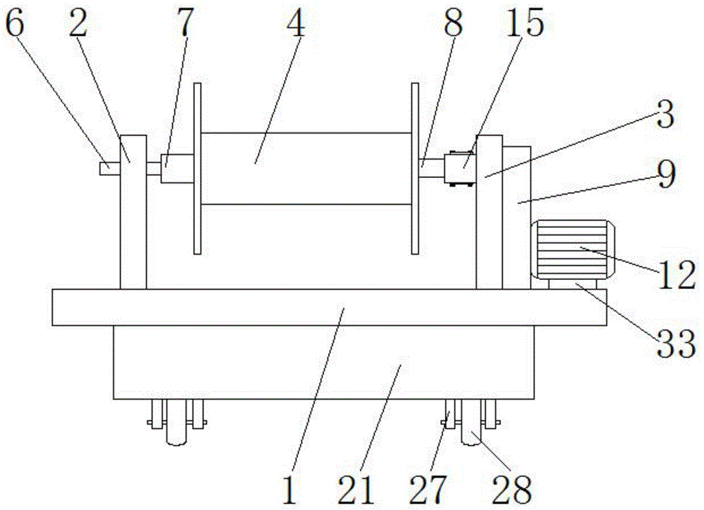
图1为本发明结构示意图;Fig. 1 is the structural representation of the present invention;
图2为本发明连接杆套管连接结构的剖视示意图;FIG. 2 is a schematic cross-sectional view of the connecting rod casing connection structure of the present invention;
图3为本发明外壳内部连接结构的剖视示意图;Fig. 3 is the cross-sectional schematic diagram of the internal connection structure of the casing of the present invention;
图4为本发明第一支撑架与轴承连接结构的侧视示意图;4 is a schematic side view of the first support frame and the bearing connection structure of the present invention;
图5为本发明箱体内部连接结构的剖视示意图。FIG. 5 is a schematic cross-sectional view of the internal connection structure of the box according to the present invention.
图中:1、固定架;2、第一支撑架;3、第二支撑架;4、放线辊;5、轴承;6、固定轴;7、螺纹套;8、连接杆;9、外壳;10、传动杆;11、从动齿轮;12、第一电机;13、转杆;14、主动齿轮;15、套管;16、弹簧;17、垫板;18、固定块;19、卡块;20、卡槽;21、箱体;22、螺栓;23、第二电机;24、螺纹杆;25、螺纹块;26、加固杆;27、支架;28、滚轮;29、支杆;30、滑轮;31、滑槽;32、开口;33、固定座。In the figure: 1. Fixed frame; 2. First support frame; 3. Second support frame; 4. Pay-off roller; 5. Bearing; 6. Fixed shaft; 7. Threaded sleeve; 8. Connecting rod; ;10, transmission rod; 11, driven gear; 12, first motor; 13, rotating rod; 14, driving gear; 15, sleeve; 16, spring; 17, backing plate; 18, fixed block; 19, clip block; 20, card slot; 21, box body; 22, bolt; 23, second motor; 24, threaded rod; 25, threaded block; 26, reinforcement rod; 27, bracket; 28, roller; 29, support rod; 30, pulley; 31, chute; 32, opening; 33, fixed seat.
具体实施方式Detailed ways
下面将结合本发明实施例中的附图,对本发明实施例中的技术方案进行清楚、完整地描述,显然,所描述的实施例仅仅是本发明一部分实施例,而不是全部的实施例。基于本发明中的实施例,本领域普通技术人员在没有做出创造性劳动前提下所获得的所有其他实施例,都属于本发明保护的范围。The technical solutions in the embodiments of the present invention will be clearly and completely described below with reference to the accompanying drawings in the embodiments of the present invention. Obviously, the described embodiments are only a part of the embodiments of the present invention, but not all of the embodiments. Based on the embodiments of the present invention, all other embodiments obtained by those of ordinary skill in the art without creative efforts shall fall within the protection scope of the present invention.
在发明的描述中,需要说明的是,术语“上”、“下”、“内”、“外”“前端”、“后端”、“两端”、“一端”、“另一端”等指示的方位或位置关系为基于附图所示的方位或位置关系,仅是为了便于描述本发明和简化描述,而不是指示或暗示所指的装置或元件必须具有特定的方位、以特定的方位构造和操作,因此不能理解为对本发明的限制。此外,术语“第一”、“第二”仅用于描述目的,而不能理解为指示或暗示相对重要性。In the description of the invention, it should be noted that the terms "upper", "lower", "inner", "outer", "front end", "rear end", "two ends", "one end", "the other end", etc. The indicated orientation or positional relationship is based on the orientation or positional relationship shown in the accompanying drawings, which is only for the convenience of describing the present invention and simplifying the description, rather than indicating or implying that the indicated device or element must have a specific orientation or a specific orientation. construction and operation, and therefore should not be construed as limiting the invention. Furthermore, the terms "first" and "second" are used for descriptive purposes only and should not be construed to indicate or imply relative importance.
在发明的描述中,需要说明的是,除非另有明确的规定和限定,术语“安装”、“设置有”、“连接”等,应做广义理解,例如“连接”,可以是固定连接,也可以是可拆卸连接,或一体地连接;可以是机械连接,也可以是电连接;可以是直接相连,也可以通过中间媒介间接相连,可以是两个元件内部的连通。对于本领域的普通技术人员而言,可以具体情况理解上述术语在本发明中的具体含义。In the description of the invention, it should be noted that, unless otherwise expressly specified and limited, the terms "installed", "provided with", "connected", etc. should be understood in a broad sense, for example, "connected" may be a fixed connection, It can also be a detachable connection, or an integral connection; it can be a mechanical connection or an electrical connection; it can be a direct connection, or an indirect connection through an intermediate medium, or the internal communication between the two components. For those of ordinary skill in the art, the specific meanings of the above terms in the present invention can be understood in specific situations.
本发明所采用的部件均为通用标准件或本领域技术人员知晓的部件,其结构和原理都为本技术人员均可通过技术手册得知或通过常规实验方法获知。The components used in the present invention are all common standard components or components known to those skilled in the art, and the structures and principles thereof are known to those skilled in the art through technical manuals or through routine experimental methods.
请参阅图1-5,一种捻股机用方便更换线圈的放线装置,包括固定架1,固定架1顶部的左侧固定连接有第一支撑架2,第一支撑架2的形状为U形,第一电机12的底部固定连接有固定座33,固定架1顶部的右侧固定连接有第二支撑架3,第一支撑架2与第二支撑架3之间活动连接有放线辊4,第一支撑架2的内腔固定连接有轴承5,轴承5的内腔转动连接有固定轴6,放线辊4的左侧固定连接有螺纹套7,螺纹套7与固定轴6的右侧螺纹连接,放线辊4的右侧固定连接有连接杆8,第二支撑架3的右侧固定连接有外壳9,外壳9内腔右侧的顶部活动连接有传动杆10,传动杆10的表面固定连接有从动齿轮11,外壳9右侧的底部固定连接有第一电机12,第一电机12的输出端固定连接有转杆13,转杆13的左侧贯穿至外壳9的内腔,转杆13的表面固定连接有与从动齿轮11配合使用的主动齿轮14,传动杆10的左侧贯穿外壳9的内腔并延伸至第二支撑架3的左侧,传动杆10的左侧固定连接有套管15,套管15内腔的右侧固定连接有弹簧16,弹簧16的左侧固定连接有垫板17,连接杆8的右侧延伸至套管15的内腔并与垫板17接触,套管15的顶部和底部均设置有固定块18,固定块18远离套管15的一侧螺纹连接有螺栓22,螺栓22的数量为两个,螺栓22的一侧与套管15螺纹连接,两个固定块18相对的一侧固定连接有卡块19,卡块19远离固定块18的一侧延伸至套管15的内腔,连接杆8的顶部和底部均开设有与卡块19配合使用的卡槽20,固定架1的底部固定连接有箱体21,箱体21内腔的底部固定连接有第二电机23,第二电机23的输出端固定连接有螺纹杆24,螺纹杆24的表面螺纹连接有螺纹块25,螺纹块25的一侧固定连接有加固杆26,加固杆26的底部固定连接有支架27,支架27的底部通过转轴活动连接有滚轮28,加固杆26远离螺纹套7的一侧固定连接有支杆29,支杆29的一侧活动连接有滑轮30,箱体21内腔的一侧开设有与滑轮30配合使用的滑槽31,箱体21底部的两侧开设有与滚轮28配合使用的开口32,第二电机23的两侧均固定连接有加固块,加固块的底部与箱体21内腔的底部固定连接,通过设置螺栓22,能够对固定块18进行固定,从而保证了套管15与连接杆8之间的稳定性,保证了放线辊4在转动时的稳定性,通过设置第二电机23、螺纹杆24、螺纹套7、加固杆26、支架27和滚轮28,能够便于对该装置进行移动,同时提高了装置的稳定性,达到更加便捷的使用方式,通过设置支杆29、滑轮30、滑槽31和开口32的配合使用,能够对加固杆26进行限位,从而使加固杆26稳定的上升和下降,通过设置固定座33,能够便于对第一电机12进行支撑,从而保证了第一电机12的稳定性,通过固定架1、第一支撑架2、第二支撑架3、放线辊4、轴承5、固定轴6、螺纹套7、连接杆8、外壳9、传动杆10、从动齿轮11、第一电机12、转杆13、主动齿轮14、套管15、弹簧16、垫板17、固定块18、卡块19、卡槽20和箱体21的配合使用,能够有效对传统捻股机的放线装置进行改进,在保持原有自转的基础上,扩大工字轮的适配范围,并做到拆卸和安装方便,减少人员搬运的使用,从而达到提高工作效率和产品质量的目的。Please refer to Figures 1-5, a wire pay-off device for a twisting machine that is convenient for replacing coils, including a
使用时,对放线辊4进行拆卸时,通过取下固定套管15与固定块18之间的螺栓22,便可取出固定块18,使得卡块19脱离卡槽20的内腔,此时连接杆8处于活动状态,能够从套管15中取出,将放线辊4左侧的螺纹套7与固定轴6松动分离,从而能够取下放线辊4,带动放线辊4实现自转时,通过外设控制器启动第一电机12,第一电机12带动转杆13转动,转杆13带动主动齿轮14转动,主动齿轮14带动从动齿轮11转动,从动齿轮11带动传动杆10转动,传动杆10带动套管15转动,套管15带动连接杆8转动,从而能够使放线辊4实现自转,对该装置进行移动时,通过启动第二电机23,第二电机23带动螺纹杆24转动,螺纹杆24带动螺纹块25下降,螺纹块25带动加固杆26下降,加固杆26带动支架27下降,支架27带动滚轮28支撑地面,从而能够使设备进行移动,通过外设控制器反向转动第二电机23时,能够带动支架27和滚轮28收缩至箱体21的内部,从而保证了设备在使用过程中的稳定性,使得工作人员的操作更加便利,该装置便于拆换线圈,操作较为简便。When in use, when disassembling the pay-off roller 4, the fixing
尽管已经示出和描述了本发明的实施例,对于本领域的普通技术人员而言,可以理解在不脱离本发明的原理和精神的情况下可以对这些实施例进行多种变化、修改、替换和变型,本发明的范围由所附权利要求及其等同物限定。Although embodiments of the present invention have been shown and described, it will be understood by those skilled in the art that various changes, modifications, and substitutions can be made in these embodiments without departing from the principle and spirit of the invention and modifications, the scope of the present invention is defined by the appended claims and their equivalents.
Claims (6)
Priority Applications (1)
| Application Number | Priority Date | Filing Date | Title |
|---|---|---|---|
| CN201911035153.9A CN110884940A (en) | 2019-10-29 | 2019-10-29 | Stranding machine is with pay-off of conveniently changing coil |
Applications Claiming Priority (1)
| Application Number | Priority Date | Filing Date | Title |
|---|---|---|---|
| CN201911035153.9A CN110884940A (en) | 2019-10-29 | 2019-10-29 | Stranding machine is with pay-off of conveniently changing coil |
Publications (1)
| Publication Number | Publication Date |
|---|---|
| CN110884940A true CN110884940A (en) | 2020-03-17 |
Family
ID=69746574
Family Applications (1)
| Application Number | Title | Priority Date | Filing Date |
|---|---|---|---|
| CN201911035153.9A Pending CN110884940A (en) | 2019-10-29 | 2019-10-29 | Stranding machine is with pay-off of conveniently changing coil |
Country Status (1)
| Country | Link |
|---|---|
| CN (1) | CN110884940A (en) |
Cited By (2)
| Publication number | Priority date | Publication date | Assignee | Title |
|---|---|---|---|---|
| CN111331811A (en) * | 2020-04-26 | 2020-06-26 | 安徽汉唐光缆有限公司 | Butterfly-shaped leading-in optical cable production line |
| CN112653020A (en) * | 2020-10-15 | 2021-04-13 | 湖南理工职业技术学院 | Cable moving device for electric power construction and using method thereof |
Citations (5)
| Publication number | Priority date | Publication date | Assignee | Title |
|---|---|---|---|---|
| CN108116466A (en) * | 2017-12-25 | 2018-06-05 | 苏州聚飞纺织科技有限公司 | A kind of textile process transporter |
| CN207861528U (en) * | 2017-11-08 | 2018-09-14 | 保定茂华塑料制品有限公司 | A kind of agricultural mulching draw off gear |
| CN208198468U (en) * | 2018-04-11 | 2018-12-07 | 浙江嘉昱达机械有限公司 | Cart is used in a kind of detection of drug |
| CN208829009U (en) * | 2018-08-18 | 2019-05-07 | 江苏德顺纺织有限公司 | A kind of section warping sizing winding device |
| CN211895427U (en) * | 2019-10-29 | 2020-11-10 | 南京引力工业焊接技术研究院有限公司 | Stranding machine is with pay-off of conveniently changing coil |
-
2019
- 2019-10-29 CN CN201911035153.9A patent/CN110884940A/en active Pending
Patent Citations (5)
| Publication number | Priority date | Publication date | Assignee | Title |
|---|---|---|---|---|
| CN207861528U (en) * | 2017-11-08 | 2018-09-14 | 保定茂华塑料制品有限公司 | A kind of agricultural mulching draw off gear |
| CN108116466A (en) * | 2017-12-25 | 2018-06-05 | 苏州聚飞纺织科技有限公司 | A kind of textile process transporter |
| CN208198468U (en) * | 2018-04-11 | 2018-12-07 | 浙江嘉昱达机械有限公司 | Cart is used in a kind of detection of drug |
| CN208829009U (en) * | 2018-08-18 | 2019-05-07 | 江苏德顺纺织有限公司 | A kind of section warping sizing winding device |
| CN211895427U (en) * | 2019-10-29 | 2020-11-10 | 南京引力工业焊接技术研究院有限公司 | Stranding machine is with pay-off of conveniently changing coil |
Cited By (3)
| Publication number | Priority date | Publication date | Assignee | Title |
|---|---|---|---|---|
| CN111331811A (en) * | 2020-04-26 | 2020-06-26 | 安徽汉唐光缆有限公司 | Butterfly-shaped leading-in optical cable production line |
| CN112653020A (en) * | 2020-10-15 | 2021-04-13 | 湖南理工职业技术学院 | Cable moving device for electric power construction and using method thereof |
| CN112653020B (en) * | 2020-10-15 | 2022-02-15 | 湖南理工职业技术学院 | Cable moving device for electric power construction and using method thereof |
Similar Documents
| Publication | Publication Date | Title |
|---|---|---|
| CN206969873U (en) | A kind of pay off rack of cables manufacturing production | |
| CN202796426U (en) | Wire supplying device of coiling equipment | |
| CN203568583U (en) | Take-up machine | |
| CN110775708A (en) | A pay-off device | |
| CN208700273U (en) | A kind of wirerope quickly winds collection device | |
| CN215870528U (en) | Electronic communication wire laying device | |
| CN107649616A (en) | Bar straightener and its application method | |
| CN104743413A (en) | Manual wire payoff and takeup device | |
| CN214424060U (en) | Installation elevation adjusting device of prefabricated building | |
| CN106516884A (en) | Cable take-up mechanism | |
| CN106783147B (en) | Production equipment for cylindrical windings of substation transformers | |
| CN214298671U (en) | Winding and winding device for cable processing | |
| CN207957382U (en) | A kind of building is electromechanical to use cable coiling device | |
| CN107555264A (en) | A kind of cable Winder and its method of work | |
| CN216679584U (en) | Single-wire multistage metal wire drawing machine | |
| CN214298641U (en) | Cable coiling device | |
| CN205380229U (en) | Novel electric power cable copper wire straightening machine | |
| CN211895427U (en) | Stranding machine is with pay-off of conveniently changing coil | |
| CN207451261U (en) | An automatic pay-off machine | |
| CN206219879U (en) | A kind of Ding Jin testing agencies for strander | |
| CN212070278U (en) | Feeding device for steel bar straightening machine | |
| CN214693030U (en) | Multifunctional winching machine | |
| CN117208663A (en) | A cable take-up device for electric power | |
| CN204847574U (en) | Drum support | |
| CN212269042U (en) | Paying-off device |
Legal Events
| Date | Code | Title | Description |
|---|---|---|---|
| PB01 | Publication | ||
| PB01 | Publication | ||
| SE01 | Entry into force of request for substantive examination | ||
| SE01 | Entry into force of request for substantive examination | ||
| RJ01 | Rejection of invention patent application after publication | ||
| RJ01 | Rejection of invention patent application after publication |
Application publication date: 20200317 |