CN110860986A - Roller shaft bar cutting device of chain link - Google Patents
Roller shaft bar cutting device of chain link Download PDFInfo
- Publication number
- CN110860986A CN110860986A CN201911297520.2A CN201911297520A CN110860986A CN 110860986 A CN110860986 A CN 110860986A CN 201911297520 A CN201911297520 A CN 201911297520A CN 110860986 A CN110860986 A CN 110860986A
- Authority
- CN
- China
- Prior art keywords
- cylinder
- shaft
- base
- support
- grinding wheel
- Prior art date
- Legal status (The legal status is an assumption and is not a legal conclusion. Google has not performed a legal analysis and makes no representation as to the accuracy of the status listed.)
- Pending
Links
Images


Classifications
-
- B—PERFORMING OPERATIONS; TRANSPORTING
- B24—GRINDING; POLISHING
- B24B—MACHINES, DEVICES, OR PROCESSES FOR GRINDING OR POLISHING; DRESSING OR CONDITIONING OF ABRADING SURFACES; FEEDING OF GRINDING, POLISHING, OR LAPPING AGENTS
- B24B27/00—Other grinding machines or devices
- B24B27/06—Grinders for cutting-off
-
- B—PERFORMING OPERATIONS; TRANSPORTING
- B24—GRINDING; POLISHING
- B24B—MACHINES, DEVICES, OR PROCESSES FOR GRINDING OR POLISHING; DRESSING OR CONDITIONING OF ABRADING SURFACES; FEEDING OF GRINDING, POLISHING, OR LAPPING AGENTS
- B24B41/00—Component parts such as frames, beds, carriages, headstocks
- B24B41/02—Frames; Beds; Carriages
-
- B—PERFORMING OPERATIONS; TRANSPORTING
- B24—GRINDING; POLISHING
- B24B—MACHINES, DEVICES, OR PROCESSES FOR GRINDING OR POLISHING; DRESSING OR CONDITIONING OF ABRADING SURFACES; FEEDING OF GRINDING, POLISHING, OR LAPPING AGENTS
- B24B45/00—Means for securing grinding wheels on rotary arbors
- B24B45/006—Quick mount and release means for disc-like wheels, e.g. on power tools
-
- B—PERFORMING OPERATIONS; TRANSPORTING
- B24—GRINDING; POLISHING
- B24B—MACHINES, DEVICES, OR PROCESSES FOR GRINDING OR POLISHING; DRESSING OR CONDITIONING OF ABRADING SURFACES; FEEDING OF GRINDING, POLISHING, OR LAPPING AGENTS
- B24B47/00—Drives or gearings; Equipment therefor
- B24B47/02—Drives or gearings; Equipment therefor for performing a reciprocating movement of carriages or work- tables
- B24B47/06—Drives or gearings; Equipment therefor for performing a reciprocating movement of carriages or work- tables by liquid or gas pressure only
-
- B—PERFORMING OPERATIONS; TRANSPORTING
- B24—GRINDING; POLISHING
- B24B—MACHINES, DEVICES, OR PROCESSES FOR GRINDING OR POLISHING; DRESSING OR CONDITIONING OF ABRADING SURFACES; FEEDING OF GRINDING, POLISHING, OR LAPPING AGENTS
- B24B51/00—Arrangements for automatic control of a series of individual steps in grinding a workpiece
Landscapes
- Engineering & Computer Science (AREA)
- Mechanical Engineering (AREA)
- Finish Polishing, Edge Sharpening, And Grinding By Specific Grinding Devices (AREA)
Abstract
本发明公开了一种链条节的滚轴棒料切割装置,底座上安装纵横行走机构,纵横行走机构的纵向行走板上端安装夹紧机械手,夹紧机械手的一侧设切割装置,纵横行走机构、夹紧机械手和切割装置的运作由外接的高压气体和电路控制运行,本发明由气缸控制砂轮上下移动完成夹紧棒料切割,电磁阀控制气缸活塞的伸缩来实现夹紧和放松,整个机器由PLC控制各个气动换向阀的电磁铁,由气缸驱动完成顺序切割动作过程,随动工作台的随动前进速度也可以通过夹紧机械手夹紧铸棒使之与铸棒速度同步,控制方便,性能稳定,结构简单,调节、修改方便、生产率高等优点。
The invention discloses a roller bar cutting device for chain links. A vertical and horizontal traveling mechanism is installed on a base, a clamping manipulator is installed on the upper end of a vertical traveling plate of the vertical and horizontal traveling mechanism, and a cutting device is arranged on one side of the clamping manipulator. The vertical and horizontal traveling mechanism, The operation of the clamping manipulator and the cutting device is controlled by the external high-pressure gas and circuit. In the present invention, the cylinder controls the grinding wheel to move up and down to complete the clamping and cutting of the bar material, and the solenoid valve controls the expansion and contraction of the cylinder piston to realize clamping and loosening. PLC controls the electromagnets of each pneumatic reversing valve, and is driven by the cylinder to complete the sequential cutting process. The follow-up speed of the follow-up table can also be synchronized with the speed of the cast bar by clamping the manipulator, which is convenient to control. It has the advantages of stable performance, simple structure, convenient adjustment and modification, and high productivity.
Description
技术领域technical field
本发明涉及一种链条生产装备类技术领域,尤其是链条节的滚轴棒料切割装置。The invention relates to the technical field of chain production equipment, in particular to a roller bar cutting device for chain links.
背景技术Background technique
各节链条间用连接销的初始原材料均为棒料,直径较大的为圆棒,直径较小的为筒卷料拉直后在切割为技术规定的长度,后续在进一步金加工。在长期的棒料切断时,大多是采用切割机的方式人工切割,切割方式的工作效率低下是严重制约加工成本居高不下和人机配置较多的问题。The initial raw materials of the connecting pins between each chain are bars, the larger diameter is a round bar, and the smaller diameter is a coiled material that is straightened and then cut to the length specified by the technology, and then further gold processing. In the long-term bar cutting, most of the cutting machines are used for manual cutting. The low working efficiency of the cutting method is a serious problem that restricts the high processing cost and many man-machine configurations.
发明内容SUMMARY OF THE INVENTION
为解决上述技术问题,本发明的目的在于提供链条节的滚轴棒料切割装置,底座上安装纵横行走机构,纵横行走机构的纵向行走板上端安装夹紧机械手,夹紧机械手的一侧设切割装置,纵横行走机构、夹紧机械手和切割装置的运作由外接的高压气体和电路控制运行,本发明由气缸控制砂轮上下移动完成夹紧棒料切割,电磁阀控制气缸活塞的伸缩来实现夹紧和放松,整个机器由PLC控制各个气动换向阀的电磁铁,由气缸驱动完成顺序切割动作过程,随动工作台的随动前进速度也可以通过夹紧机械手夹紧铸棒使之与铸棒速度同步,控制方便,性能稳定,结构简单,调节、修改方便、生产率高等优点。In order to solve the above-mentioned technical problems, the object of the present invention is to provide a roller bar cutting device for chain links, a vertical and horizontal traveling mechanism is installed on the base, a clamping manipulator is installed at the upper end of the vertical traveling plate of the vertical and horizontal traveling mechanism, and one side of the clamping manipulator is provided with a cutting machine. The operation of the device, the vertical and horizontal travel mechanism, the clamping manipulator and the cutting device are controlled by the external high-pressure gas and circuit. The whole machine is controlled by PLC to control the electromagnets of each pneumatic reversing valve, and is driven by the cylinder to complete the sequential cutting action process. Speed synchronization, convenient control, stable performance, simple structure, convenient adjustment and modification, high productivity.
为达到上述目的,本发明的技术方案是:链条节的滚轴棒料切割装置,包括底座,所述底座上安装纵横行走机构,所述纵横行走机构的纵向行走板上端安装夹紧机械手,夹紧机械手的一侧设切割装置,纵横行走机构、夹紧机械手和切割装置的运作由外接的高压气体和电路控制运行;In order to achieve the above purpose, the technical scheme of the present invention is: a roller bar cutting device for a chain link, comprising a base, a vertical and horizontal traveling mechanism is installed on the base, and a clamping manipulator is installed on the upper end of the vertical traveling plate of the There is a cutting device on one side of the tightening manipulator, and the operation of the vertical and horizontal traveling mechanism, the clamping manipulator and the cutting device is controlled by an external high-pressure gas and circuit;
底座上的纵横行走机构设气缸一,所述气缸一一端的伸缩杆与底座右端固定的固定架连接,气缸一另一端的伸缩杆头部设气缸接头一,所述气缸接头一连接耳座一,横向行走板底部的耳座四与气缸一的伸缩杆连接固定,横向行走板下端两侧均设滑块,所述滑块与底座上端两侧的钟祥导轨二嵌入式连接,横向行走板上端两侧设与下端滑块位置垂直的直线导轨一,所述直线导轨一与纵向行走板下端两侧的滑块连接,纵向行走板中间位置设耳座二,气缸二的连接固定在横向行走板上的耳座三,气缸二的伸缩杆与耳座二连接,气缸二的伸缩杆一端设气缸接头二与耳座五用销轴连接,整体连接后,横向行走板相对与横向行走板腾空且能在气缸二的带动下沿着直线导轨一移动;The vertical and horizontal walking mechanism on the base is provided with a cylinder one, the telescopic rod at one end of the cylinder is connected with the fixing frame fixed at the right end of the base, and the head of the telescopic rod at the other end of the cylinder one is provided with a cylinder joint one, and the cylinder joint one is connected to the
纵横行走机构上设的切割装置的支座五上端内设轴套,销轴穿入轴套内把电机支座连接,所述电机支座上设电机,二片支架二的一端分别设置电机支座两侧且连接并能以销轴为基准俯仰式摆动,支架二的另一端设支座四,所述支座四内设轴,所述轴两端的设角接触轴承,角接触轴承的外侧设封油环和轴承端盖,轴一端安装两端均装砂轮卡盘的砂轮片,砂轮罩与支座四端面固定且把砂轮片局部包围,外侧的砂轮卡盘外设挡板一且用紧固螺丝把砂轮卡盘和砂轮片与轴固定,轴的另一端设带轮,传动带把带轮与电机旋转轴上的传动轮传动连接,支架二偏中间位置设朝下的支座三与气缸三伸缩杆头部的气缸接头三连接,气缸三底部的气缸尾座连接支座一,支座一与纵向行走板固定;The upper end of the support five of the cutting device installed on the vertical and horizontal traveling mechanism is provided with a shaft sleeve, and the pin shaft penetrates into the shaft sleeve to connect the motor support, the motor support is provided with a motor, and one end of the two brackets is respectively provided with a motor support The two sides of the seat are connected and can be tilted swinging based on the pin shaft. The other end of the bracket two is provided with a support four. The support four is provided with a shaft inside. Set oil seal ring and bearing end cover, one end of the shaft is installed with grinding wheel disc with grinding wheel chuck at both ends, the grinding wheel cover is fixed with the four end faces of the support and partially surrounds the grinding wheel piece, the outer grinding wheel chuck is equipped with a baffle plate and used Tighten the screw to fix the grinding wheel chuck and the grinding wheel to the shaft. The other end of the shaft is provided with a pulley. The transmission belt connects the pulley with the transmission wheel on the rotating shaft of the motor. The cylinder joints at the head of the three telescopic rods of the cylinder three are connected, and the cylinder tailstock at the bottom of the cylinder three is connected with the support one, and the support one is fixed with the longitudinal walking plate;
纵横行走机构上安装的夹紧机械手在切割装置的一侧,所述夹紧机械手的底座二内设开口槽且底部与纵向行走板固定,静臂嵌入安装在底座二的开口槽内,上动臂在开口槽的上端,静臂与上动臂中间的连接块对称与底座二的开口槽用连接轴连接且连接后静臂与上动臂能以连接轴为基轴咬合式摆动,底座二的开口槽上端设气缸四,气缸四的一端与底座二的开口槽用连接轴固定,气缸四的另一端连接搁置在支撑块上的滚轮,所述滚轮连接两件连杆,所述连杆另一端分别各与静臂与上动臂连接,连接后两件连杆呈V形且前端为夹紧爪,静臂与上动臂的另一端均设向内伸展的支点顶块,两件支点顶块的凹槽内设限位块。The clamping manipulator installed on the vertical and horizontal walking mechanism is on one side of the cutting device. The base two of the clamping manipulator is provided with an opening groove and the bottom is fixed with the vertical walking plate. The static arm is embedded in the opening groove of the base two and moves upward. The arm is at the upper end of the opening slot, the connecting block between the static arm and the upper boom is symmetrical with the opening slot of the base two and is connected with a connecting shaft, and after the connection, the static arm and the upper moving arm can swing with the connecting shaft as the base shaft. The upper end of the opening slot is provided with a
进一步设置,所述电机的旋转轴与带轮连接内设平键一。It is further arranged that a flat key is set inside the connection between the rotating shaft of the motor and the pulley.
进一步设置,所述带轮与轴连接端设键,带轮外侧面设挡板二且用紧固螺丝把带轮与轴固定。It is further arranged that the connecting end of the pulley and the shaft is provided with a key, the outer side of the pulley is provided with two baffle plates, and the pulley and the shaft are fixed with tightening screws.
本发明的有益效果是:本发明由气缸控制砂轮上下移动完成夹紧棒料切割,电磁阀控制气缸活塞的伸缩来实现夹紧和放松,整个机器由PLC控制各个气动换向阀的电磁铁,由气缸驱动完成顺序切割动作过程,随动工作台的随动前进速度也可以通过夹紧机械手夹紧铸棒使之与铸棒速度同步,控制方便,性能稳定,结构简单,调节、修改方便、生产率高等优点。The beneficial effects of the invention are: the cylinder controls the grinding wheel to move up and down to complete the clamping bar cutting, the solenoid valve controls the expansion and contraction of the cylinder piston to realize clamping and loosening, and the PLC controls the electromagnets of each pneumatic reversing valve in the whole machine. Driven by the cylinder to complete the sequential cutting action process, the follow-up speed of the follow-up table can also be synchronized with the speed of the cast bar by clamping the manipulator, which is convenient to control, stable in performance, simple in structure, convenient in adjustment and modification, High productivity.
附图说明Description of drawings
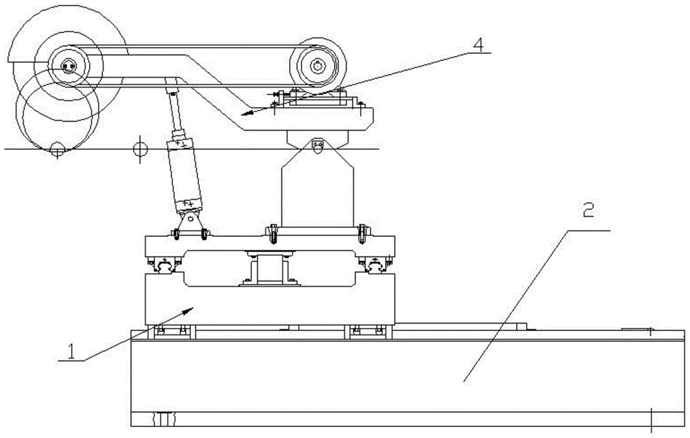
图1为本发明的示意图;Fig. 1 is the schematic diagram of the present invention;
图2为图1的俯视图;Fig. 2 is the top view of Fig. 1;
图3为图1的左视图;Fig. 3 is the left side view of Fig. 1;
图4为图3中夹紧机械手的右视图;Fig. 4 is the right side view of the clamping manipulator in Fig. 3;
图5图1中纵横行走机构1的示意图;Fig. 5 is the schematic diagram of the vertical and
图6为图5的俯视图;Fig. 6 is the top view of Fig. 5;
图7为图5的左视图;Fig. 7 is the left side view of Fig. 5;
图8为图7中A向的放大图;Fig. 8 is the enlarged view of A direction in Fig. 7;
图9为图1中切割装置的示意图;Fig. 9 is the schematic diagram of the cutting device in Fig. 1;
图10为图9的左视图;Fig. 10 is the left side view of Fig. 9;
图11为本发明的气动原理图;Fig. 11 is the pneumatic principle diagram of the present invention;
图12为本发明的电路连接图。FIG. 12 is a circuit connection diagram of the present invention.
图中:纵横行走机构1、气缸接头一102、耳座一103、耳座二108、滑块1010、直线导轨一1011、横向行走板1012、气缸一1013、气缸二1017、耳座三1018、耳座四1023、气缸接头二1026、耳座五1027、销轴1028、滑块1030、直线导轨二1031、纵向行走板1032、底座2、切割装置4、支座一401、气缸三402、砂轮片403、支架二404、传动带405、支座三408、平键一4013、电机4014、电机支座4015、定位板4016、气缸尾座4018、销轴4019、轴套4020、挡板一4024、砂轮卡盘4025、砂轮罩4026、支座四4030、轴4031、轴承端盖4032、封油环4033、带轮4034、键4035、紧固螺丝4036、挡板二4037、角接触轴承4038、气缸接头三4039、支座五4042、夹紧机械手7、底座二701、支撑块702、连杆703、滚轮704、气缸四705、上动臂706、静臂7061、支点顶块707、限位块708、夹紧爪709。In the figure: Vertical and
具体实施方式Detailed ways
下面通过实施例,并结合附图,对本发明的技术方案作进一步具体的说明。The technical solutions of the present invention will be further described in detail below through embodiments and in conjunction with the accompanying drawings.
如图1~图3所示,链条节的滚轴棒料切割装置,包括底座2,所述底座2上安装纵横行走机构1,所述纵横行走机构1的纵向行走板1032上端安装夹紧机械手7,夹紧机械手7的一侧设切割装置4,纵横行走机构1、夹紧机械手7和切割装置4的运作由外接的高压气体和电路控制运行;As shown in FIGS. 1 to 3 , the roller bar cutting device for chain links includes a
如图5~图8所示,底座2上的纵横行走机构1设气缸一1013,所述气缸一1013一端的伸缩杆与底座2右端固定的固定架连接,气缸一1013另一端的伸缩杆头部设气缸接头一102,所述气缸接头一102连接耳座一103,横向行走板1012底部的耳座四1023与气缸一1013的伸缩杆连接固定,横向行走板1012下端两侧均设滑块1030,所述滑块1030与底座2上端两侧的钟祥导轨二1031嵌入式连接,横向行走板1012上端两侧设与下端滑块1030位置垂直的直线导轨一1011,所述直线导轨一1011与纵向行走板1032下端两侧的滑块1010连接,纵向行走板1032中间位置设耳座二108,气缸二1017的连接固定在横向行走板1012上的耳座三1018,气缸二1017的伸缩杆与耳座二108连接,气缸二1017的伸缩杆一端设气缸接头二1026与耳座五1027用销轴1028连接,整体连接后,横向行走板1012相对与横向行走板1012腾空且能在气缸二1017的带动下沿着直线导轨一1011移动;As shown in Figures 5 to 8, the vertical and
如图9~图10纵横行走机构1上设的切割装置4的支座五4042上端内设轴套4020,销轴4019穿入轴套4020内把电机支座4015连接,所述电机支座4015上设电机4014,二片支架二404的一端分别设置电机支座4015两侧且连接并能以销轴4019为基准俯仰式摆动,支架二404的另一端设支座四4030,所述支座四4030内设轴4031,所述轴4031两端的设角接触轴承4038,角接触轴承4038的外侧设封油环4033和轴承端盖4032,轴4031一端安装两端均装砂轮卡盘4025的砂轮片403,砂轮罩4026与支座四4030端面固定且把砂轮片403局部包围,外侧的砂轮卡盘4025外设挡板一4024且用紧固螺丝把砂轮卡盘4025和砂轮片403与轴4031固定,轴4031的另一端设带轮4034,传动带405把带轮4034与电机4014旋转轴上的传动轮传动连接,支架二404偏中间位置设朝下的支座三408与气缸三402伸缩杆头部的气缸接头三4039连接,气缸三402底部的气缸尾座4018连接支座一401,支座一401与纵向行走板1032固定;As shown in FIG. 9-FIG. 10, the upper end of the support five 4042 of the
如图4所示,纵横行走机构1上安装的夹紧机械手7在切割装置4的一侧,所述夹紧机械手7的底座二701内设开口槽且底部与纵向行走板1032固定,静臂7061嵌入安装在底座二701的开口槽内,上动臂706在开口槽的上端,静臂7061与上动臂706中间的连接块对称与底座二701的开口槽用连接轴连接且连接后静臂7061与上动臂706能以连接轴为基轴咬合式摆动,底座二701的开口槽上端设气缸四705,气缸四705的一端与底座二701的开口槽用连接轴固定,气缸四705的另一端连接搁置在支撑块702上的滚轮704,所述滚轮704连接两件连杆703,所述连杆703另一端分别各与静臂7061与上动臂706连接,连接后两件连杆703呈V形且前端为夹紧爪709,静臂7061与上动臂706的另一端均设向内伸展的支点顶块707,两件支点顶块707的凹槽内设限位块708。As shown in FIG. 4 , the
所述电机4014的旋转轴与带轮连接内设平键一4013,使电机4014的旋转轴与带轮连接角度位置锁止固定。A flat key 4013 is set inside the connection between the rotating shaft of the
所述带轮4034与轴4031连接端设键4035,带轮4034外侧面设挡板二4037且用紧固螺丝4036把带轮4034与轴4031固定。The connecting end of the
本技术方案主要由三个大的部分组成,即切割部分、夹紧部分和纵横行走部分,切割部分是由电机4014带动砂轮片403旋转,由气缸三402控制砂轮片403上下移动完成切割。夹紧部分主要采用了一个气动夹紧机械手7,电磁阀控制气缸活塞的伸缩来实现夹紧和放松。纵横行走部分是由气缸控制纵向、横向行走板,使之沿直线导轨前进或返回,整个机器由PLC控制各个气动换向阀的电磁铁,由气缸驱动完成顺序切割动作过程,而随动工作台的随动前进速度也可以通过夹紧机械手夹紧铸棒使之与铸棒速度同步,横向切割时的切割速度可以通过气缸来调节。The technical solution is mainly composed of three large parts, namely the cutting part, the clamping part and the vertical and horizontal walking part. The cutting part is driven by the
与一般的切割机相比,这种切割机有以下优点:Compared with the general cutting machine, this cutting machine has the following advantages:
一、实现了机械工程和自动控制的有效结合,机械部分采用机械优化设计,整个设计过程中都进行了综合技术比较与经济评价,实现了预定的功能。1. It realizes the effective combination of mechanical engineering and automatic control. The mechanical part adopts mechanical optimization design. In the whole design process, comprehensive technical comparison and economic evaluation are carried out to realize the predetermined function.
二、整个运动过程都采用了气压传动控制,与液压传动相比,气压传动有无介质费用、处理方便、无泄露污染、无介质变质等优点。2. The entire movement process adopts pneumatic transmission control. Compared with hydraulic transmission, pneumatic transmission has the advantages of no medium cost, convenient handling, no leakage pollution, and no medium deterioration.
三、在设计过程中,纵横行走装置采用了直线导轨,既提高了运动系统的运动精度,又很大程度的减小了摩擦力,达到了节能的效果。3. In the design process, the vertical and horizontal walking device adopts linear guide rail, which not only improves the motion accuracy of the motion system, but also reduces the friction force to a great extent, and achieves the effect of energy saving.
四、整个切割过程都由PCL控制,以其结构简单合理、设备性能良好、使用寿命长、安全系数高等因素,满足了自动化大批量的生产要求。4. The entire cutting process is controlled by PCL, which meets the requirements of automated mass production due to its simple and reasonable structure, good equipment performance, long service life and high safety factor.
这种切割机具有控制方便,性能稳定,结构简单,调节、修改方便、生产率高等优点,具有广阔的应用前景。This cutting machine has the advantages of convenient control, stable performance, simple structure, convenient adjustment and modification, and high productivity, and has broad application prospects.
本装置的工作是由PLC控制电磁阀,使电磁阀控制气缸,并由气缸驱动与其连接的部件,实现对铸棒的准确定长切割,切割后自动返回初始位置。一个切割机分别切割两条铸棒,其切口深度为35mm,然后由压断机进行压断。The work of the device is to control the solenoid valve by PLC, so that the solenoid valve controls the cylinder, and the cylinder drives the components connected to it, so as to realize the accurate fixed-length cutting of the cast rod, and automatically return to the initial position after cutting. A cutting machine cuts two cast rods respectively, and the incision depth is 35mm, and then they are cut by a crushing machine.
铸棒线切割机是一种既能有效的提高生产率,又在价格和使用方面能被广大用户所接受的一种新型的自动控制切割机,由PLC控制的气动铸棒切割机,融合了气压自动控制、机器人技术和PLC控制技术。PLC控制各个气动换向阀的电磁铁,由气缸驱动机械手完成顺序切割过程,实现了机械设计、电器控制和气动控制的有效结合。这种切割机具有控制方便,性能稳定,结构简单,调节、维修方便,生产率高等优点,具有广泛的应用前景。Cast bar wire cutting machine is a new type of automatic control cutting machine that can not only effectively improve productivity, but also be accepted by the majority of users in terms of price and use. The pneumatic cast bar cutting machine controlled by PLC integrates air pressure. Automatic control, robotics and PLC control technology. PLC controls the electromagnets of each pneumatic reversing valve, and the cylinder drives the manipulator to complete the sequential cutting process, realizing the effective combination of mechanical design, electrical control and pneumatic control. This cutting machine has the advantages of convenient control, stable performance, simple structure, convenient adjustment and maintenance, high productivity, and has wide application prospects.
切割方案:电机通过带传动带动砂轮片转动。夹紧机构不但在切割之前机械手抓能够根据事先收到的信号准确地运动到每个工位,而且在切割过程中要夹紧运动着的铸铁棒,使砂轮与铸棒同步。夹紧部分是由气缸推动机械手实现夹紧和放松的。它是用一个机械手同时负责夹紧两根铸棒,根据需要对被切割的那条进行夹紧。纵横行走装置主要是为了配合切割装置和夹紧装置,使砂轮片和夹紧机械手能够在走刀过程中横向移动,迅速准确地达到工作位,在切割过程中能够随着铸棒纵向移动,切完后在返回初始位置。纵横行走装置主要是为了实现切割机砂轮片的纵向和横向移动,使之完成切割动作。Cutting scheme: The motor drives the grinding wheel to rotate through the belt drive. The clamping mechanism not only moves the manipulator to each station accurately according to the signal received in advance before cutting, but also clamps the moving cast iron bar during the cutting process to synchronize the grinding wheel with the cast bar. The clamping part is clamped and released by the cylinder pushing the manipulator. It uses a manipulator to clamp two cast rods at the same time, and clamps the cut one as needed. The vertical and horizontal traveling device is mainly to cooperate with the cutting device and the clamping device, so that the grinding wheel and the clamping manipulator can move laterally during the cutting process, and reach the working position quickly and accurately. Return to the original position when finished. The vertical and horizontal walking device is mainly to realize the vertical and horizontal movement of the grinding wheel of the cutting machine, so that it can complete the cutting action.
本技术方案主要工作分为两大部分,第一部分为切割机的机械设计,其中主要包括砂轮片的选择、电机的选择、砂轮片传动方式的选择和优化、电机和砂轮的安装、各个气缸力的计算及其参数选择计算、滑动导轨的设计以及其他部分和整体结构的设计,第二部分为电气原理及控制部分的设计,启动如图11显示的气动控制原理控制,如图12显示了电气原理图的设计、配线图的设计、控制柜的设计及电路控制面板的设计。The main work of this technical solution is divided into two parts. The first part is the mechanical design of the cutting machine, which mainly includes the selection of grinding wheel, the selection of motor, the selection and optimization of the transmission mode of grinding wheel, the installation of motor and grinding wheel, and the force of each cylinder. The calculation and parameter selection calculation, the design of the sliding guide rail and the design of other parts and the overall structure, the second part is the design of the electrical principle and the control part, start the control of the pneumatic control principle shown in Figure 11, and the electrical control shown in Figure 12. Schematic design, wiring diagram design, control cabinet design and circuit control panel design.
本技术方案中的输入设备是电气控制系统进行信号才的界面设备,完成人与机之间的信号采集和机与机之间的信号采集。操作人员发出的主令信号通过按钮、各类手动开关送入控制系统,现场自动运行的控制信号通过行程开关等现场检测设备送入控制系统。The input device in the technical solution is an interface device for the electrical control system to perform signal acquisition, and completes signal acquisition between humans and machines and signal acquisition between machines. The main command signal sent by the operator is sent into the control system through buttons and various manual switches, and the control signal of automatic operation on site is sent into the control system through the on-site detection equipment such as the travel switch.
本技术方案中的输出设备是用控制系统发出的控制信号去控制执行机构,实现要求的运动的输出和显示设备运行的状态。被信号驱动的执行机构有继电器、交流接触器、控制液压系统的电磁阀、信号显示灯等。The output device in the technical solution uses the control signal sent by the control system to control the actuator, so as to realize the output of the required motion and display the running state of the device. The actuators driven by the signal include relays, AC contactors, solenoid valves that control the hydraulic system, and signal display lights.
本技术方案中的逻辑控制系统根据给定的控制对输入设备送来的控制、检测信号进行计算处理,并将计算结果转换为控制信号经输出设备控制机械设备运行。组成控制系统的器件有两类:一是继电器控制系统,其控制逻辑由硬件构成,另一类为用可编程控制器构成的控制系统,其控制逻辑由编程软件构成。The logic control system in the technical solution calculates and processes the control and detection signals sent by the input device according to the given control, and converts the calculation result into a control signal to control the operation of the mechanical device through the output device. There are two types of devices that make up the control system: one is the relay control system, whose control logic is composed of hardware, and the other is the control system composed of programmable controllers, whose control logic is composed of programming software.
本行业的技术人员也了解,本发明不受上述实施案例的限制,上述实施案例和说明书中描述的只是说明本发明的原理,在不脱离本发明连接计范畴前提下,本发明还会有各种变化和改进,这些变化和改进都落入要求保护的本发明范围内。本发明要求保护范围由所附的权利要求书及其等效物界定。Those skilled in the art also understand that the present invention is not limited by the above-mentioned implementation cases. The above-mentioned implementation cases and descriptions in the description are only to illustrate the principle of the present invention. Such changes and improvements fall within the scope of the claimed invention. The claimed scope of the present invention is defined by the appended claims and their equivalents.
Claims (3)
Priority Applications (1)
| Application Number | Priority Date | Filing Date | Title |
|---|---|---|---|
| CN201911297520.2A CN110860986A (en) | 2019-12-17 | 2019-12-17 | Roller shaft bar cutting device of chain link |
Applications Claiming Priority (1)
| Application Number | Priority Date | Filing Date | Title |
|---|---|---|---|
| CN201911297520.2A CN110860986A (en) | 2019-12-17 | 2019-12-17 | Roller shaft bar cutting device of chain link |
Publications (1)
| Publication Number | Publication Date |
|---|---|
| CN110860986A true CN110860986A (en) | 2020-03-06 |
Family
ID=69659658
Family Applications (1)
| Application Number | Title | Priority Date | Filing Date |
|---|---|---|---|
| CN201911297520.2A Pending CN110860986A (en) | 2019-12-17 | 2019-12-17 | Roller shaft bar cutting device of chain link |
Country Status (1)
| Country | Link |
|---|---|
| CN (1) | CN110860986A (en) |
Cited By (2)
| Publication number | Priority date | Publication date | Assignee | Title |
|---|---|---|---|---|
| CN111702644A (en) * | 2020-07-03 | 2020-09-25 | 南京工业职业技术学院 | A bar cutting machine |
| CN111843674A (en) * | 2020-08-05 | 2020-10-30 | 郑州工业应用技术学院 | A kind of auxiliary trimming device for wall and roof for architectural decoration |
Citations (6)
| Publication number | Priority date | Publication date | Assignee | Title |
|---|---|---|---|---|
| DE1704789A1 (en) * | 1968-03-01 | 1971-06-03 | Gottfried Bitterlich | Foam cutting machine |
| WO2016207499A1 (en) * | 2015-06-24 | 2016-12-29 | Eaton Leonard Group | Device for bending profile members comprising tools for bending profile members and a tool for cutting said profile members |
| CN206464954U (en) * | 2017-01-22 | 2017-09-05 | 宁波大学 | A kind of bar cutting machine |
| CN110340437A (en) * | 2018-04-03 | 2019-10-18 | 湖北乾奥建设工程有限公司 | Fully automatic cutting machine for building pipe cutting |
| CN110340954A (en) * | 2018-04-03 | 2019-10-18 | 湖北乾奥建设工程有限公司 | The atmospheric control of building pipe fully automatic cutting machine |
| CN212122812U (en) * | 2019-12-17 | 2020-12-11 | 浙江来源机械有限公司 | Roller bearing bar cutting device of chain festival |
-
2019
- 2019-12-17 CN CN201911297520.2A patent/CN110860986A/en active Pending
Patent Citations (6)
| Publication number | Priority date | Publication date | Assignee | Title |
|---|---|---|---|---|
| DE1704789A1 (en) * | 1968-03-01 | 1971-06-03 | Gottfried Bitterlich | Foam cutting machine |
| WO2016207499A1 (en) * | 2015-06-24 | 2016-12-29 | Eaton Leonard Group | Device for bending profile members comprising tools for bending profile members and a tool for cutting said profile members |
| CN206464954U (en) * | 2017-01-22 | 2017-09-05 | 宁波大学 | A kind of bar cutting machine |
| CN110340437A (en) * | 2018-04-03 | 2019-10-18 | 湖北乾奥建设工程有限公司 | Fully automatic cutting machine for building pipe cutting |
| CN110340954A (en) * | 2018-04-03 | 2019-10-18 | 湖北乾奥建设工程有限公司 | The atmospheric control of building pipe fully automatic cutting machine |
| CN212122812U (en) * | 2019-12-17 | 2020-12-11 | 浙江来源机械有限公司 | Roller bearing bar cutting device of chain festival |
Cited By (3)
| Publication number | Priority date | Publication date | Assignee | Title |
|---|---|---|---|---|
| CN111702644A (en) * | 2020-07-03 | 2020-09-25 | 南京工业职业技术学院 | A bar cutting machine |
| CN111843674A (en) * | 2020-08-05 | 2020-10-30 | 郑州工业应用技术学院 | A kind of auxiliary trimming device for wall and roof for architectural decoration |
| CN111843674B (en) * | 2020-08-05 | 2021-07-27 | 郑州工业应用技术学院 | A kind of auxiliary trimming device for wall and roof for architectural decoration |
Similar Documents
| Publication | Publication Date | Title |
|---|---|---|
| CN102951576B (en) | Dual-drive body-in-white lifting working platform | |
| CN203665526U (en) | Full-automatic loading-unloading mechanical arm | |
| CN205651120U (en) | Whole process automation anchor clamps of EMUs car body side wall and system of processing | |
| CN211812267U (en) | A crucible automatic turning over clamping and positioning mechanism | |
| CN102079068A (en) | Hydraulic supporting, leveling and clamping device of large-size working piece | |
| CN105215098A (en) | A kind of bender and using method thereof | |
| CN105127637A (en) | Automatic welding clamp for cross type iron tower workpiece | |
| CN205056721U (en) | Bending machine | |
| CN208350270U (en) | A kind of pressure switch automatic Regulation detection device | |
| CN212122812U (en) | Roller bearing bar cutting device of chain festival | |
| CN211991643U (en) | Multi-station synchronous rotation positioner | |
| CN104801582A (en) | Rotary left-right pipe bending machine | |
| CN201613507U (en) | Large workpiece hydraulic support leveling and clamping device | |
| CN211276956U (en) | Automatic change ultrasonic welding special plane | |
| CN113357222A (en) | Novel hydraulic mechanism LVDT connects device | |
| CN202428183U (en) | Automatic chamfering and reaming device for shaft sleeve machining | |
| CN208289516U (en) | A kind of hardware machinery part processing material-pulling device | |
| CN202344885U (en) | Mold changing auxiliary device of stamping machine | |
| CN105810474A (en) | Third assembling mechanism of limiting switch assembling machine | |
| CN215199367U (en) | Three-dimensional manipulator | |
| CN105826103B (en) | The rotating disk mechanism of limit switch main body kludge | |
| CN211539264U (en) | Cylinder pusher | |
| CN113927315B (en) | Manufacturing equipment and manufacturing method suitable for curved side wall of motor car cab | |
| CN105328630B (en) | A kind of engine piston is installed automatically and control device and its design method | |
| CN108655469B (en) | Special processing equipment for replacing turning with milling |
Legal Events
| Date | Code | Title | Description |
|---|---|---|---|
| PB01 | Publication | ||
| PB01 | Publication | ||
| SE01 | Entry into force of request for substantive examination | ||
| SE01 | Entry into force of request for substantive examination | ||
| WD01 | Invention patent application deemed withdrawn after publication |
Application publication date: 20200306 |
|
| WD01 | Invention patent application deemed withdrawn after publication |