Three-port direct current converter and control method and circuit thereof
Technical Field
The invention belongs to the technical field of power electronics, and particularly relates to a three-port direct-current converter, a control method and a control circuit thereof.
Background
In recent years, with the increasing environmental pollution and energy crisis problems, it has become a hot point of research to generate electricity by using new energy such as solar energy, hydrogen energy, wind energy, and the like. The new energy power generation system is divided into two operation modes of grid-connected operation and independent operation according to whether the new energy power generation system is connected with a power grid or not, the independently operated new energy power generation system is widely applied to power supply of non-power grid areas such as remote mountainous areas, islands, industrial parks and the like due to the advantages of simple structure, high power supply quality and the like, and in addition, the independently operated new energy power generation system is also widely applied to power supply of new energy automobiles and independent LED lighting systems. However, since the output characteristics of the new energy power generation system are often closely related to environmental factors, and the output characteristics of the new energy power generation system have randomness and volatility under different environmental conditions, an energy storage unit must be equipped in the independently operated new energy power generation system to store and regulate electric energy so as to meet the requirements of power supply continuity and stability of power utilization loads.
In a traditional new energy power generation system, because an input source, energy storage equipment and a load need to be managed simultaneously, a plurality of independent converters are often needed for electric energy conversion and energy management, the system is complex in structure, low in efficiency and high in cost, and centralized control cannot be achieved. In order to further improve the efficiency of the system, the cost of the system is reduced. In view of the above problems of the system, researchers have proposed to apply a three-port converter to a new energy power generation system, thereby improving the efficiency of the system, reducing the cost, increasing the power density, and realizing centralized control. There are many documents that propose topologies of three-port converters, such as the documents "Hongfei Wu, Peng Xu, Haibing Hu, Zhou Zihu, Yan xing. multiple converters based on integration of full-bridge and bidirectional dc-topologies for renewable generation systems, IEEE trans. ind. electron, 2014,61(2), 856-869", "Jianwu Zeng, weii Qiao, Liyan Qu,Yanping Jiao,An isolated multiport dc-dc converter for simultaneous power management of multhe topology is suitable for application occasions with high voltage grade and high Power. However, the problems of large number of devices, large volume, low power density, high cost and complex control exist.
Disclosure of Invention
Aiming at the defects of the prior art, the invention provides six three-port direct-current converters which can simultaneously realize the power flow management among an input power source, an energy storage device and a load, and a control method and a control circuit thereof.
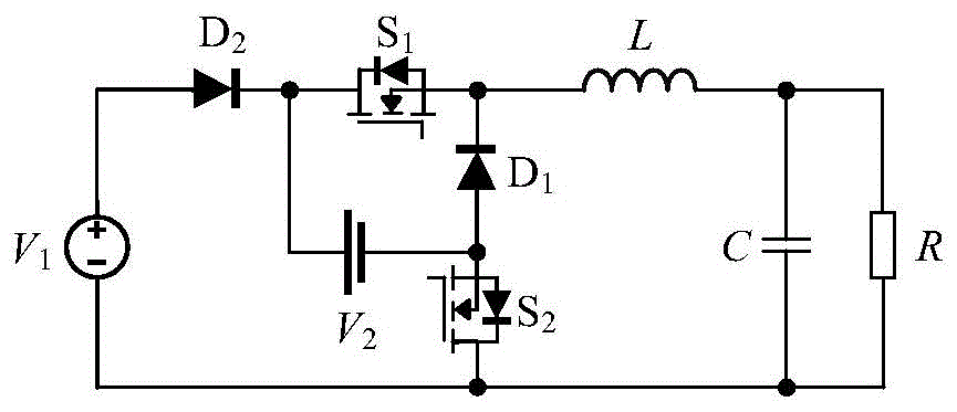
The first three-port DC converter includes a first switch tube S1A second switch tube S2A first diode D1A second diode D2And an energy storage inductor L; d2Is connected to S1Of the drain electrode, S1Is connected to D1And one end of L, D1Is connected to S2A source electrode of (a); d2And S2And a positive and a negative electrode respectively being input terminals, D2And S2The source electrode of (1) and the anode and the cathode which are respectively an energy storage end, the other end of L and S2The drain electrodes of (1) are respectively the anode and the cathode of the load end.
The second three-port DC converter comprises a first switch tube S1A second switch tube S2A first diode D1A second diode D2And an energy storage inductor L; one end of L is connected to S1Drain electrode of (1) and (D)1Of the anode, S1Is connected to D2Anode of (D)1Is connected to S2A drain electrode of (1); the other end of L and D2The cathodes of (a) are respectively the positive and negative poles of the input terminal, D1And S1The source electrodes of (1) are respectively the anode and the cathode of the energy storage end, S2Source electrode and D2The cathodes of (a) are respectively the positive electrode and the negative electrode of the load end.
The third three-port DC converter comprises a first switch tube S1A second switch tube S2A first diode D1A second diode D2And an energy storage inductor L; d2Is connected to S1Of the drain electrode, S1Is connected to D1And one end of L, D1Is connected to S2A source electrode of (a); d2The other end of the L and the anode of the L are respectively a positive pole and a negative pole of the input end, D2And D1The anodes of (A) are respectively the anode and the cathode of the energy storage end, S2And the other end of the L is a positive electrode and a negative electrode of the load end respectively.
A fourth three-port DC converter including a first switch tube S1A second switch tube S2A first diode D1A second diode D2A first energy storage inductor L1A second energy storage inductor L2And an energy storage capacitor C1;L1Is connected at one end to D2And C1One end of (A), C1Is connected at the other end to S2And L is2One end of (A), D2Is connected to S1Of the drain electrode, S2Is connected to D1Anode of (D)1Is connected to S1A source electrode of (a); l is1And the other end of (1) and S1The source electrodes of (1) are respectively the positive electrode and the negative electrode of the input end, D2And S2The source electrodes of (1) are respectively the anode and the cathode of an energy storage end, L2And another end of D1The cathodes of (a) are respectively the positive electrode and the negative electrode of the load end.
The fifth three-port DC converter comprises a first switch tube S1A second switch tube S2A first diode D1A second diode D2A first energy storage inductor L1A second energy storage inductor L2And an energy storage capacitor C1;L1Is connected at one end to S1Drain electrode of (1) and C1One end of (A), C1Is connected at the other end to D1And L2One end of (A), S1Is connected to D2Anode of (D)1Is connected to S2Of the drain electrode, L2Is connected at the other end to D2A cathode of (a); l is1And another end of D2The cathodes of (a) are respectively the positive pole and the negative pole of the input endPole, D1And S1The source electrodes of (1) are respectively the anode and the cathode of the energy storage end, S2Source and L of2The other ends of the two ends are respectively a positive electrode and a negative electrode of the load end.
A sixth three-port DC converter, comprising a first switch tube S1A second switch tube S2A first diode D1A second diode D2A first energy storage inductor L1A second energy storage inductor L2And an energy storage capacitor C1;D2Is connected to S1Of the drain electrode, S1Is connected to L1And C and1one end of (A), C1Is connected at the other end to D1And L2One end of (A), D1Is connected to S2Source of (2), S2Is connected to L1The other end of (a); d2And L1The other ends of the two electrodes are respectively a positive electrode and a negative electrode of the input end, D2And D1The anodes of (A) are respectively the anode and the cathode of the energy storage end, L2And the other end of (1) and S2The drain electrodes of (1) are respectively the anode and the cathode of the load end.
Control method of three-port direct current converter, and sampling value v of input voltage of direct current converter1And a reference value V1_refAfter error amplification, the signal is mixed with sawtooth wave vtComparing to generate a drive signal Vgs1Controlling a first switching tube of the direct current converter; at the same time, the sampled value v of the load voltage of the DC converteroAnd a reference value Vo_refAfter error amplification, the signal is mixed with sawtooth wave vtComparing to generate a drive signal Vgs2And controlling a second switching tube of the direct current converter.
Further, a reference value V of the input voltage1_refFrom sampled values v of the input voltage of the DC converter1And the input current sample value i1Obtained by MPPT algorithm.
A control circuit of a three-port DC converter includes a first error amplifier EA1, a second error amplifier EA2, a first comparator CMP1 and a second comparator CMP 2; input end of EA1 for input direct current converterSampling value v of input voltage1And a reference value V1_refThe output terminal is connected to the positive input terminal of the CMP 1; input end of EA2 is used for inputting sampled value v of load voltage of direct current converteroAnd a reference value Vo_refThe output terminal is connected to the positive input terminal of the CMP 2; the negative inputs of CMP1 and CMP2 are for inputting sawtooth wave vt(ii) a The output end of the CMP1 is used for connecting the grid electrode of the first switch tube of the direct current converter, and the output end of the CMP2 is used for connecting the grid electrode of the second switch tube of the direct current converter.
Further, the MPPT controller is also included; the input end of the MPPT controller is used for inputting a sampling value v of the input voltage of the direct current converter1And the input current sample value i1And the output is connected to an input of EA 1.
Compared with the prior art, the invention has the beneficial effects that:
(1) power management and control among the input source, the energy storage device and the load can be achieved by adopting a single converter.
(2) The converter only comprises two switching tubes, so that the cost is low and the control is simple.
(3) Single-stage power conversion is carried out between any two ports, and centralized control can be realized.
Drawings
Fig. 1 is a schematic diagram of a first three-port dc converter.
Fig. 2 is a schematic diagram of a second three-port dc converter.
Fig. 3 is a schematic diagram of a third three-port dc converter.
Fig. 4 is a schematic diagram of a fourth three-port dc converter.
Fig. 5 is a schematic diagram of a fifth three-port dc converter.
Fig. 6 is a schematic diagram of a sixth three-port dc converter.
Fig. 7 is a schematic diagram of a control circuit of a three-port dc converter.
Fig. 8 shows two driving signals of a three-port dc converter.
FIG. 9 is a fourth three port DCEquivalent circuit for four switching states of the converter. Wherein, FIG. 9(a) shows the first switch tube S1And a second switching tube S2Equivalent circuit when conducting simultaneously, FIG. 9(b) is the first switch tube S1Conducting the second switch tube S2An equivalent circuit at the time of turn-off, and FIG. 9(c) shows the first switching tube S1Off, the second switching tube S2An equivalent circuit when conducting, and FIG. 9(d) shows the first switch tube S1And a second switching tube S2And an equivalent circuit when the circuit is turned off.
Fig. 10 is a simulation result of the fourth three-port dc converter at the time of load jump.
Fig. 11 is a simulation result of the fourth three-port dc converter at the time of input transition.
Symbolic illustration in fig. 10 and 11: v. of1Is the voltage across the input source, i1Is the current of the input source, voIs the voltage across the load, ioFor the current flowing through the load, ibatFor discharge current of energy storage device, iL1And iL2Respectively, a first energy storage inductor L1And a second energy storage inductor L2Current of (I)batIs the average value of the energy storage device current.
Detailed Description
The invention is further described with reference to the following figures and specific examples.
FIG. 1 shows a first three-port DC converter, comprising an input source V1Energy storage device V2A first switch tube S1A second switch tube S2A first diode D1A second diode D2Energy storage inductance L, filter capacitor C and load R, wherein: second diode D2Anode and input source V1Is connected to the anode of a second diode D2Respectively connected with the negative pole of the energy storage device and the first switch tube S1Is connected with the drain electrode of the first switching tube S1With the source of the energy storage inductor L and the first diode D, respectively1Is connected to the cathode of a first diode D1Respectively with an energy storage device V2Positive pole and second switch tube S2Is connected to the source electrodeThe other end of the energy storage inductor L is respectively connected to one end of the filter capacitor C and one end of the load R, and the other end of the load R is respectively connected to the input source V1Negative electrode of (1), second switching tube S2And the other end of the filter capacitor C.
FIG. 2 shows a second three-port DC converter, comprising an input source V1Energy storage device V2A first switch tube S1A second switch tube S2A first diode D1A second diode D2Energy storage inductance L, filter capacitor C and load R, wherein: one end of the energy storage inductor L and the input source V1The other end of the energy storage inductor L is respectively connected to the first diode D1And a first switching tube S1The first switch tube S1Respectively with the energy storage device V2And a second diode D2Is connected to the anode of a first diode D1Respectively with the energy storage device V2And a second switching tube S2Is connected with the drain electrode of the second switching tube S2Is connected to one end of the filter capacitor C and one end of the load R, the other end of the load R is connected to the input source V1Negative electrode of (1), second diode D2Is connected to the other end of the filter capacitor C.
FIG. 3 shows a third three-port DC converter, comprising an input source V1Energy storage device V2A first switch tube S1A second switch tube S2A first diode D1A second diode D2Energy storage inductance L, filter capacitor C and load R, wherein: second diode D2Anode and input source V1Is connected to the anode of a second diode D2Respectively with the energy storage device V2Negative pole of (2) and first switch tube S1Is connected with the source electrode of the first switching tube S1With one end of the energy storage inductor L and the first diode D, respectively1Is connected to the cathode of a first diode D1Respectively with an energy storage device V2Positive pole and second switch tube S2Is connected with the source electrode of the second switch tube S2Are respectively connected to the filterOne end of the capacitor C and one end of the load R, the other end of the load R is respectively connected to the input source V1The other end of the energy storage inductor L and the other end of the filter capacitor C.
FIG. 4 shows a fourth three-port DC converter, comprising an input source V1Energy storage device V2A first switch tube S1A second switch tube S2A first diode D1A second diode D2A first energy storage inductor L1A second energy storage inductor L2And an energy storage capacitor C1Filter capacitor C2And a load R, wherein: first energy storage inductor L1One end of (1) and an input source V1Is connected with the positive pole of the first energy storage inductor L1The other end of the capacitor is respectively connected with an energy storage capacitor C1And a second diode D2Is connected to the anode of a second diode D2Respectively with the energy storage device V2Positive pole and first switch tube S1Is connected with the drain electrode of the energy storage capacitor C1The other end of the first energy storage inductor is respectively connected with a second energy storage inductor L2And a second switching tube S2Is connected to the drain of the second switching tube S2Respectively with the energy storage device V2Negative electrode of (2) and first diode D1Is connected with the anode of the second energy storage inductor L2The other end of the filter is respectively connected with a filter capacitor C2Is connected to one end of a load R, the other end of the load R being connected to an input source V, respectively1Negative electrode of (1), first switching tube S1Source electrode of, the first diode D1Cathode and filter capacitor C2And the other end of the same.
FIG. 5 shows a fifth three-port DC converter, which includes an input source V1Energy storage device V2A first switch tube S1A second switch tube S2A first diode D1A second diode D2A first energy storage inductor L1A second energy storage inductor L2And an energy storage capacitor C1Filter capacitor C2And a load R, wherein: first energy storage inductor L1One end of (1) and an input source V1Is connected with the positive pole of the first energy storage inductor L1The other end of the capacitor is respectively connected with an energy storage capacitor C1And a first switching tube S1Is connected with the drain electrode of the first switching tube S1Respectively with the energy storage device V2And a second diode D2Is connected with an energy storage capacitor C1The other end of the first energy storage inductor is respectively connected with a second energy storage inductor L2And a first diode D1Is connected to the anode of a first diode D1Respectively with the energy storage device V2Positive pole and second switch tube S2Is connected with the drain electrode of the second switching tube S2Are respectively connected to the filter capacitors C2And one end of a load R, the other end of the load R being connected to an input source V, respectively1Negative electrode of (1), second diode D2Cathode and second energy storage inductor L2Another terminal of (1) and a filter capacitor C2And the other end of the same.
FIG. 6 shows a sixth three-port DC converter, which includes an input source V1Energy storage device V2A first switch tube S1A second switch tube S2A first diode D1A second diode D2A first energy storage inductor L1A second energy storage inductor L2And an energy storage capacitor C1Filter capacitor C2And a load R, wherein: second diode D2Anode and input source V1Is connected to the anode of a second diode D2Respectively with the first switching tube S1And energy storage device V2Is connected to the positive pole of the first switching tube S1Respectively with the first energy storage inductor L1One terminal of and an energy storage capacitor C1Is connected to an energy storage capacitor C1Are respectively connected to the first diode D1And the second energy storage inductor L2One terminal of (1), a first diode D1Respectively with an energy storage device V2And a second switching tube S2Is connected to the source of a second energy-storing inductor L2The other end of the filter is respectively connected with a filter capacitor C2Is connected with one end of a load R, and the other end of the load R is respectively connected with an input source V1Negative pole, first energy storage inductance L1Another terminal of (1), a first diode D1And an anode ofFilter capacitor C2And the other end of the same.
Wherein the last three converters are added with an energy storage capacitor C1And a second energy storage inductor L2Compared with the first three converters, the three-phase inverter has the technical effects of smaller voltage constraint between ports, wider application range and continuous input/output current.
The control method of the three-port direct current converter comprises the following steps: input source V1Voltage sampled value v1And a reference value V1_refAfter error amplification, the signal is mixed with sawtooth wave vtComparing to generate a drive signal Vgs1Controlling a first switching tube S1(ii) a At the same time, the voltage sampling value v of the load RoAnd a reference value Vo_refAfter error amplification, the signal is mixed with sawtooth wave vtComparing to generate a drive signal Vgs2Controlling the second switch tube S2. The control method can be applied to the six two-switch three-port direct-current converters. In particular, as input source V1For new energy, the reference value V of the input voltage1_refFrom an input source V1Voltage sampled value v1And the input current sample value i1Obtained by MPPT (maximum power point tracking) algorithm.
The control method may adopt a control circuit as shown in fig. 7, including: an MPPT controller, a first error amplifier EA1, a second error amplifier EA2, a first comparator CMP1, and a second comparator CMP 2. MPPT controller input as input source V1Is sampled by a voltage v1And a sampling current i1The output of the first error amplifier EA1 is connected to one input end of a first error amplifier EA1, the other input end of which is an input source V1Is sampled by a voltage v1The output of the first error amplifier EA1 is connected to one input terminal of a first comparator CMP1, and the other input terminal of the first comparator CMP1 is a sawtooth wave vtThe input of the second error amplifier EA2 is a sampled value v of the load voltageoAnd a reference value Vo_refThe output terminal is connected to one input terminal of a second comparator CMP2, and the other input terminal of the second comparator CMP2 is a sawtooth wave vt. The output of the first comparator CMP1 is taken as the firstSwitch tube S1The output of the second comparator CMP2 is used as the second switch tube S2By adjusting the first switching tube S1The duty ratio of the second switching tube S is adjusted to adjust the power of the input source2The duty cycle of (a) regulates the load voltage. Wherein the MPPT controller is used to obtain the input voltage reference value V1_refNormally for the input source V1Is the case of new energy.
Fig. 8 shows two possible switch drive signals after the use of the control circuit. Under the first switch driving signal, the first switch tube S1Is larger than the second switch tube S2On duty ratio of the first switching tube S under the second switching drive signal1Is smaller than the second switch tube S2On duty cycle of (d).
The first three-port DC converter requires an input source voltage v1Load voltage voAnd the voltage v of the energy storage device2Satisfies the relation v2>v1>vo(ii) a The second three-port DC converter requires an input source voltage v1Load voltage voAnd the voltage v of the energy storage device2Satisfies the relation v2>vo>v1(ii) a The third three-port DC converter requires an input source voltage v1Load voltage voAnd the voltage v of the energy storage device2Satisfies the relation v2>v1(ii) a The fourth three-port dc converter requires an input source voltage v1Load voltage voAnd the voltage v of the energy storage device2Satisfies the relation v2>v1+vo(ii) a The fifth three-port DC converter requires an input source voltage v1Load voltage voAnd the voltage v of the energy storage device2Satisfies the relation v2>vo(ii) a The sixth three-port dc converter requires an input source voltage v1Load voltage voAnd the voltage v of the energy storage device2Satisfies the relation v2>v1。
The operation principle of the present invention will be described below by taking the three-port dc converter shown in fig. 4 as an example, and the operation principles of the other five three-port dc converters are similar to the three-port dc converter.
A three-port dc converter as shown in fig. 4. In this system, an input source V1As the main power source of the system to provide energy for the load, a general photovoltaic cell, a fuel cell, etc. can be used as the input source V1When the maximum power that the input source can provide is greater than the power that the load needs, the energy storage device presents a charging state, and when the maximum power that the input source can provide is less than the power that the load needs, the energy storage device presents a discharging state. With the control circuit shown in fig. 7, the system is able to perform power flow control and management through the power relationship of the input source and the load.
FIG. 9 shows an equivalent circuit corresponding to four possible switch states of the fourth three-port DC converter, where FIG. 9(a) shows the first switch tube S1And a second switching tube S2Equivalent circuit on the same time (state 1), in which the first diode D is in the on-off state1And a second diode D2All are turned off, and the energy storage equipment is turned to the first energy storage inductor L1And a second energy storage inductor L2Discharging; FIG. 9(b) shows the first switch tube S1Conducting the second switch tube S2Equivalent circuit when switched off (state 2), in which the first diode D is in the on-off state1Off, second diode D2Conducting, the energy storage equipment does not participate in the work, and the input source V1For the first energy-storing inductor L1Charging and energy-storing capacitor C1For the second energy storage inductor L2Charging; FIG. 9(c) shows the first switch tube S1Off, the second switching tube S2An equivalent circuit when conducting (state 3), in which state the first diode D1On, the second diode D2The first energy storage inductor L is turned off, the energy storage equipment does not participate in the work1Energy supply and storage capacitor C1Charging, second energy storage inductance L2Discharging the load; FIG. 9(d) shows the first switch tube S1And a second switching tube S2Equivalent circuit when turned off at the same time (state 4), in which state the first diode D1And a second diode D2Are all conducted, the first energy storage inductor L1And a second stored energyFeeling L2Are discharged to the energy storage device.
When the first switch tube S1Is larger than the second switch tube S2At the on duty cycle (corresponding to the first switch driving signal shown in fig. 8), state 1, state 2, and state 4 occur in sequence within one switching period; when the first switch tube S1Is smaller than the second switch tube S2On duty cycle (corresponding to the second switch driving signal shown in fig. 8), state 1, state 3, and state 4 occur in sequence in one switching cycle.
Performing time domain simulation analysis on the fourth three-port direct current converter by using PSIM simulation software, wherein the input source V1Adopting a photovoltaic cell model, wherein the maximum power point voltage of the photovoltaic cell is 25V, the maximum power point current is 2A-12A, and other system parameters are set as follows: the load power range is 0W-300W, and the voltage v of the energy storage equipment180V, load voltage Vo48V, energy storage capacitor C11000 muF, filter capacitance C21000 muF, 300 muH and FsThe system simulation results are as follows, 100 kHz.
Fig. 10 shows simulation results of the fourth three-port dc converter when the load jumps between 100W and 300W, where the maximum power point current of the photovoltaic cell is 8A, and it can be seen from the simulation results that when the load jumps, the photovoltaic cell always operates at its maximum power point, the load voltage is kept constant, when the load power is 300W, the energy storage device is in a discharge state, and when the load power is 100W, the energy storage device is in a charge state.
Fig. 11 shows a simulation result of the fourth three-port dc converter when the maximum power point current of the photovoltaic jumps between 6A and 10A, where the load is kept constant at 200W, and it can be seen from the simulation result that when the input jumps, the photovoltaic cell always operates at its maximum power point, the load voltage is kept constant, when the maximum power point current of the photovoltaic cell is 6A, the energy storage device is in a discharge state, and when the maximum power point current of the photovoltaic cell is 10A, the energy storage device is in a charge state.