CN110848231A - Anti-loosening connecting pair - Google Patents
Anti-loosening connecting pair Download PDFInfo
- Publication number
- CN110848231A CN110848231A CN201911177379.2A CN201911177379A CN110848231A CN 110848231 A CN110848231 A CN 110848231A CN 201911177379 A CN201911177379 A CN 201911177379A CN 110848231 A CN110848231 A CN 110848231A
- Authority
- CN
- China
- Prior art keywords
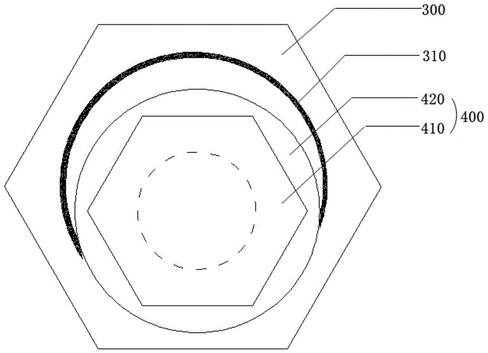
- bolt
- nut
- locking
- backstop
- thread
- Prior art date
- Legal status (The legal status is an assumption and is not a legal conclusion. Google has not performed a legal analysis and makes no representation as to the accuracy of the status listed.)
- Pending
Links
Images


Classifications
-
- F—MECHANICAL ENGINEERING; LIGHTING; HEATING; WEAPONS; BLASTING
- F16—ENGINEERING ELEMENTS AND UNITS; GENERAL MEASURES FOR PRODUCING AND MAINTAINING EFFECTIVE FUNCTIONING OF MACHINES OR INSTALLATIONS; THERMAL INSULATION IN GENERAL
- F16B—DEVICES FOR FASTENING OR SECURING CONSTRUCTIONAL ELEMENTS OR MACHINE PARTS TOGETHER, e.g. NAILS, BOLTS, CIRCLIPS, CLAMPS, CLIPS OR WEDGES; JOINTS OR JOINTING
- F16B39/00—Locking of screws, bolts or nuts
- F16B39/02—Locking of screws, bolts or nuts in which the locking takes place after screwing down
- F16B39/021—Locking of screws, bolts or nuts in which the locking takes place after screwing down by injecting a settable material after the screwing down
-
- F—MECHANICAL ENGINEERING; LIGHTING; HEATING; WEAPONS; BLASTING
- F16—ENGINEERING ELEMENTS AND UNITS; GENERAL MEASURES FOR PRODUCING AND MAINTAINING EFFECTIVE FUNCTIONING OF MACHINES OR INSTALLATIONS; THERMAL INSULATION IN GENERAL
- F16B—DEVICES FOR FASTENING OR SECURING CONSTRUCTIONAL ELEMENTS OR MACHINE PARTS TOGETHER, e.g. NAILS, BOLTS, CIRCLIPS, CLAMPS, CLIPS OR WEDGES; JOINTS OR JOINTING
- F16B39/00—Locking of screws, bolts or nuts
- F16B39/02—Locking of screws, bolts or nuts in which the locking takes place after screwing down
- F16B39/10—Locking of screws, bolts or nuts in which the locking takes place after screwing down by a plate, spring, wire or ring immovable with regard to the bolt or object and mainly perpendicular to the axis of the bolt
-
- F—MECHANICAL ENGINEERING; LIGHTING; HEATING; WEAPONS; BLASTING
- F16—ENGINEERING ELEMENTS AND UNITS; GENERAL MEASURES FOR PRODUCING AND MAINTAINING EFFECTIVE FUNCTIONING OF MACHINES OR INSTALLATIONS; THERMAL INSULATION IN GENERAL
- F16B—DEVICES FOR FASTENING OR SECURING CONSTRUCTIONAL ELEMENTS OR MACHINE PARTS TOGETHER, e.g. NAILS, BOLTS, CIRCLIPS, CLAMPS, CLIPS OR WEDGES; JOINTS OR JOINTING
- F16B39/00—Locking of screws, bolts or nuts
- F16B39/02—Locking of screws, bolts or nuts in which the locking takes place after screwing down
- F16B39/12—Locking of screws, bolts or nuts in which the locking takes place after screwing down by means of locknuts
- F16B39/16—Locking of screws, bolts or nuts in which the locking takes place after screwing down by means of locknuts in which the screw-thread of the locknut differs from that of the nut
-
- F—MECHANICAL ENGINEERING; LIGHTING; HEATING; WEAPONS; BLASTING
- F16—ENGINEERING ELEMENTS AND UNITS; GENERAL MEASURES FOR PRODUCING AND MAINTAINING EFFECTIVE FUNCTIONING OF MACHINES OR INSTALLATIONS; THERMAL INSULATION IN GENERAL
- F16B—DEVICES FOR FASTENING OR SECURING CONSTRUCTIONAL ELEMENTS OR MACHINE PARTS TOGETHER, e.g. NAILS, BOLTS, CIRCLIPS, CLAMPS, CLIPS OR WEDGES; JOINTS OR JOINTING
- F16B39/00—Locking of screws, bolts or nuts
- F16B39/22—Locking of screws, bolts or nuts in which the locking takes place during screwing down or tightening
- F16B39/24—Locking of screws, bolts or nuts in which the locking takes place during screwing down or tightening by means of washers, spring washers, or resilient plates that lock against the object
-
- F—MECHANICAL ENGINEERING; LIGHTING; HEATING; WEAPONS; BLASTING
- F16—ENGINEERING ELEMENTS AND UNITS; GENERAL MEASURES FOR PRODUCING AND MAINTAINING EFFECTIVE FUNCTIONING OF MACHINES OR INSTALLATIONS; THERMAL INSULATION IN GENERAL
- F16B—DEVICES FOR FASTENING OR SECURING CONSTRUCTIONAL ELEMENTS OR MACHINE PARTS TOGETHER, e.g. NAILS, BOLTS, CIRCLIPS, CLAMPS, CLIPS OR WEDGES; JOINTS OR JOINTING
- F16B39/00—Locking of screws, bolts or nuts
- F16B39/22—Locking of screws, bolts or nuts in which the locking takes place during screwing down or tightening
- F16B39/28—Locking of screws, bolts or nuts in which the locking takes place during screwing down or tightening by special members on, or shape of, the nut or bolt
- F16B39/282—Locking by means of special shape of work-engaging surfaces, e.g. notched or toothed nuts
Landscapes
- Engineering & Computer Science (AREA)
- General Engineering & Computer Science (AREA)
- Mechanical Engineering (AREA)
- Bolts, Nuts, And Washers (AREA)
- Connection Of Plates (AREA)
Abstract
本发明公开了一种防松动连接副,包括偏心螺栓、止退件与锁止件,所述偏心螺栓包括螺杆部,所述螺杆部的一端设有与锁止件螺纹配合的内螺母或者延伸螺栓,所述内螺母或者延伸螺栓与所述螺杆部的轴线不在同一条直线上;所述止退件套设在所述螺杆部,所述止退件朝向所述锁止件的一侧设有凸起部,所述凸起部上设有C型卡口,所述锁止件与所述止退件抵靠且卡入所述C型卡口中。当安装了所述连接副的机械处于高频振动状态时,由于多重作用的存在使本发明的连接副锁紧更为牢靠、稳定。
The invention discloses an anti-loosening connection pair, which comprises an eccentric bolt, a backstop and a locking member. The eccentric bolt includes a screw part, and one end of the screw part is provided with an inner nut or an extension threadedly matched with the locking member. Bolts, the inner nut or the extension bolt and the axis of the screw portion are not on the same line; the backstop is sleeved on the screw portion, and the backstop is provided on the side facing the locking piece. There is a protruding part, the protruding part is provided with a C-shaped bayonet, and the locking piece abuts against the backstop and is snapped into the C-shaped bayonet. When the machine on which the connecting pair is installed is in a state of high frequency vibration, the locking of the connecting pair of the present invention is more firm and stable due to the existence of multiple functions.
Description
技术领域technical field
本发明属于紧固件技术领域,具体涉及一种防松动连接副。The invention belongs to the technical field of fasteners, and in particular relates to an anti-loosening connecting pair.
背景技术Background technique
机械设备通常采用螺纹连接的方式,紧固件大都为普通螺栓和螺母连接紧固的方式即普通螺栓副,对于要经常拆运组装的金属结构产品,在拆装中提供了方便。但是这种连接方式在机械震动和变载荷的环境中容易松动。现有技术中增加摩擦力的方式使机械放松或防止螺栓、螺母之间的松动,而常用的增加摩擦力的方式为增加弹簧螺母或双螺母、镶嵌尼龙垫圈、设置凹锥或者涂抹粘合剂等方式,但是螺母会在一定间隙内松动,重复利用率低,且安装条件受到较大限制,导致现有的螺纹连接方式极其不稳定。Mechanical equipment is usually connected by threads, and most of the fasteners are connected by ordinary bolts and nuts, that is, ordinary bolt pairs. For metal structural products that need to be dismantled and assembled frequently, it provides convenience in disassembly and assembly. However, this connection method is prone to loosening in the environment of mechanical vibration and variable load. In the prior art, the way of increasing the friction force makes the machine loosen or prevents the loosening between the bolts and nuts, and the commonly used ways to increase the friction force are adding spring nuts or double nuts, inserting nylon washers, setting concave cones, or applying adhesive. However, the nut will be loose within a certain gap, the reuse rate is low, and the installation conditions are greatly restricted, resulting in extremely unstable existing threaded connection methods.
实用新型专利CN 203809476 U公开了一种防松螺母,包括具有主螺纹孔的螺母本体,具有自锁螺纹孔的自锁套,螺母本体的上端面具有向上延伸的偏心凸台,该偏心凸台的中轴线与所述主螺纹孔的中轴线具有一个偏心距离,自锁套的下端面具有套设在偏心凸台上的偏心止孔,该偏心止孔的中轴线与偏心凸台的中轴线重合,偏心止孔的内周壁与偏心凸台外周壁之间具有摩擦力,在自锁套设置在偏心凸台的初始状态下,自锁螺纹孔的中轴线与主螺纹孔的中轴线重合,同时偏心凸台的上端面与偏心止孔顶壁之间具有间隙,在自锁套相对偏心凸台偏转一个角度的状态下,所述自锁螺纹孔的中轴线与主螺纹孔的中轴线发生偏移,由于该偏移的存在使得自锁套和螺母柱体锁紧在一起,加强了防松效果。Utility model patent CN 203809476 U discloses an anti-loosening nut, comprising a nut body with a main threaded hole, a self-locking sleeve with a self-locking threaded hole, an eccentric boss extending upward on the upper end face of the nut body, the eccentric boss The central axis of the self-locking sleeve has an eccentric distance from the central axis of the main threaded hole, the lower end surface of the self-locking sleeve has an eccentric stop hole sleeved on the eccentric boss, the central axis of the eccentric stop hole and the central axis of the eccentric boss Coincidence, there is friction between the inner peripheral wall of the eccentric stop hole and the outer peripheral wall of the eccentric boss. In the initial state that the self-locking sleeve is set on the eccentric boss, the central axis of the self-locking threaded hole coincides with the central axis of the main threaded hole. At the same time, there is a gap between the upper end face of the eccentric boss and the top wall of the eccentric stop hole. When the self-locking sleeve is deflected by an angle relative to the eccentric boss, the central axis of the self-locking threaded hole and the central axis of the main threaded hole Offset, due to the existence of the offset, the self-locking sleeve and the nut cylinder are locked together, which enhances the anti-loosening effect.
普通的偏心式螺栓能够满足静置或者无需高频运作装置的安装要求,但是机械运转时往往处于高频振动状态,利用普通的偏心式螺栓进行连接很容易因机械的高频振动而松动脱落,甚至可能发生事故。Ordinary eccentric bolts can meet the installation requirements of stationary or no high-frequency operation devices, but they are often in a state of high-frequency vibration during mechanical operation. Using ordinary eccentric bolts for connection is easy to loose and fall off due to high-frequency mechanical vibration. Accidents may even occur.
发明内容SUMMARY OF THE INVENTION
针对现有技术的不足,本发明通过提供一种防松动连接副,以解决机械设备运行时在高频震动状态下,容易导致螺栓连接副松动甚至脱落的技术问题。In view of the deficiencies of the prior art, the present invention solves the technical problem that the bolted connection pair is easily loosened or even falls off under the high-frequency vibration state during operation of the mechanical equipment by providing an anti-loosening connection pair.
为实现上述目的,本发明的技术方案为:For achieving the above object, the technical scheme of the present invention is:
一种防松动连接副,包括偏心螺栓、锁止螺栓和止退件,所述偏心螺栓包括螺杆部和内螺母,所述止退件套设在所述螺杆部,所述内螺母为开设于所述螺杆部一端的凹槽,所述螺杆部的中轴线与所述内螺母的中轴线不在同一条直线上;所述锁止螺栓同轴设置依次相连的法兰部I、凸台部I和螺栓部(230),所述螺栓部(230)与所述内螺母螺纹连接;所述止退件朝向所述凸台部I的一侧设有凸起部,所述凸起部上设有C型卡口,所述锁止螺栓的凸台部I与所述止退件抵靠且卡入所述C型卡口中。An anti-loosening connection pair includes an eccentric bolt, a locking bolt and a backstop, the eccentric bolt includes a screw portion and an inner nut, the backstop is sleeved on the screw portion, and the inner nut is opened at the screw portion. The groove at one end of the screw portion, the central axis of the screw portion and the central axis of the inner nut are not on the same line; and a bolt portion (230), the bolt portion (230) is threadedly connected with the inner nut; the side of the backstop facing the boss portion I is provided with a convex portion, and a convex portion is provided on the convex portion There is a C-shaped bayonet, and the boss portion I of the locking bolt abuts against the backstop and snaps into the C-shaped bayonet.
进一步,所述螺杆部的外壁上设有外螺纹I,所述内螺母的内壁上设有内螺纹I,所述外螺纹I与所述内螺纹I的旋向相反;所述螺栓部上设有与所述内螺母旋向相同的外螺纹II。Further, the outer wall of the screw part is provided with an external thread I, the inner wall of the inner nut is provided with an internal thread I, and the rotation direction of the external thread I and the internal thread I is opposite; There is an external thread II with the same rotation direction as the internal nut.
优选的,所述外螺纹I为右旋螺纹,所述内螺纹I为左旋螺纹,所述外螺纹II为左旋螺纹。Preferably, the external thread I is a right-hand thread, the internal thread I is a left-hand thread, and the external thread II is a left-hand thread.
优选的,所述锁止螺栓的凸台部I朝向所述止退件的一侧设有齿状凸起I。Preferably, a tooth-shaped protrusion I is provided on the side of the boss portion I of the locking bolt facing the backstop.
一种防松动连接副,包括偏心螺栓、锁止螺母和止退件,所述偏心螺栓包括一体式的螺杆部和延伸螺栓,所述止退件套设在所述螺杆部,所述螺杆部的中轴线与所述延伸螺栓的中轴线不在同一条直线上;所述锁止螺母包括同轴设置有法兰部II、凸台部II和螺母部,所述螺母部穿设于所述法兰部II、凸台部II的轴心处,所述螺母部与所述延伸螺栓螺纹连接;所述止退件朝向所述凸台部II的一侧设有凸起部,所述凸起部上设有C型卡口,所述锁止螺母的凸台部II与所述止退件抵靠且卡入所述C型卡口中。An anti-loosening connection pair includes an eccentric bolt, a locking nut and a backstop, the eccentric bolt includes an integral screw portion and an extension bolt, the backstop is sleeved on the screw portion, and the screw portion The central axis of the bolt is not on the same line as the central axis of the extension bolt; the locking nut includes a flange portion II, a boss portion II and a nut portion that are coaxially arranged, and the nut portion passes through the flange portion. At the axial centers of the flange portion II and the boss portion II, the nut portion is threadedly connected with the extension bolt; the backstop member is provided with a convex portion on the side facing the boss portion II, and the convex portion is There is a C-shaped bayonet on the part, and the boss portion II of the locking nut abuts against the backstop and is snapped into the C-shaped bayonet.
进一步,所述螺杆部的外壁上设有外螺纹I,所述延伸螺栓的外壁上设有外螺纹III,所述外螺纹I与所述外螺纹III的旋向相反;所述锁止螺母内部设有与所述延伸螺栓旋向相同的内螺纹III。Further, the outer wall of the screw portion is provided with an external thread I, the outer wall of the extension bolt is provided with an external thread III, and the rotation direction of the external thread I and the external thread III is opposite; the inside of the locking nut There is an internal thread III with the same rotation direction as the extension bolt.
优选的,所述外螺纹I为右旋螺纹,所述外螺纹III为左旋螺纹,所述内螺纹III为左旋螺纹。Preferably, the external thread I is a right-hand thread, the external thread III is a left-hand thread, and the internal thread III is a left-hand thread.
优选的,所述锁止螺母的凸台部II朝向所述止退件的一侧设有齿状凸起II。Preferably, a tooth-shaped protrusion II is provided on the side of the boss portion II of the locking nut facing the backstop.
优选的,所述止退件为止退螺母,所述止退螺母上设有与所述螺杆部旋向相同的内螺纹II。Preferably, the backstop member is a backstop nut, and the backstop nut is provided with an internal thread II that is rotated in the same direction as the screw portion.
优选的,所述止退件为止退垫片,所述止退垫片通过过盈配合套设在所述偏心螺栓的螺杆部。Preferably, the backstop member is a backstop washer, and the backstop washer is sleeved on the screw portion of the eccentric bolt through interference fit.
优选的,所述偏心螺栓还包括螺帽,所述螺帽位于远离所述内螺母或者延伸螺栓的一端。Preferably, the eccentric bolt further includes a nut, and the nut is located at one end away from the inner nut or the extension bolt.
进一步,一种连接副的安装方法,包括以下步骤:Further, a method for installing a connecting pair includes the following steps:
(1)在高频振动机械上需要安装连接副的部件A和部件B上分别预留安装孔A和安装孔B,所述安装孔B的内壁上设有与所述螺杆部的外壁螺纹旋向相同的内螺纹IV,所述部件B在远离所述部件A的一侧预留用于限制所述止退垫片偏移的槽口,所述槽口的形状和尺寸与所述止退垫片相匹配;(1) A mounting hole A and a mounting hole B are reserved on the component A and component B that need to install the connection pair on the high-frequency vibration machine, and the inner wall of the mounting hole B is provided with a screw thread with the outer wall of the screw part. To the same internal thread IV, the part B reserves a notch on the side away from the part A for limiting the offset of the backstop washer, and the shape and size of the notch are the same as the backstop. Gaskets match;
(2)将所述偏心螺栓的螺杆部沿安装孔A穿过,然后沿安装孔B旋出;(2) Pass the screw portion of the eccentric bolt along the mounting hole A, and then unscrew it along the mounting hole B;
(3)将止退垫片按入槽口内,并使止退垫片套设在所述偏心螺栓的螺杆部;所述止退垫片的凸起部的一端朝外,且所述止退垫片的凸起部为环状;(3) Press the backstop washer into the slot, and set the backstop washer on the screw portion of the eccentric bolt; one end of the convex portion of the backstop washer faces outward, and the backstop The raised part of the gasket is annular;
(4)利用现有的磨平工具与偏心螺栓配合,所述磨平工具的打磨头与所述锁止螺栓或所述锁止螺母的凸台部外径相同,将磨平工具的打磨头与所述止退垫片的凸起部重叠的部分磨平形成所述C型卡口;(4) Use the existing flattening tool to cooperate with the eccentric bolt. The grinding head of the flattening tool is the same as the outer diameter of the boss part of the locking bolt or the locking nut. The part overlapping with the convex part of the backstop washer is ground to form the C-shaped bayonet;
(5)将所述锁止螺栓或所述锁止螺母与所述偏心螺栓旋紧,并使所述锁止螺栓或所述锁止螺母卡入所述C型卡口处,从而使所述偏心螺栓与所述锁止螺栓或所述锁止螺母处于锁止状态。(5) Tighten the locking bolt or the locking nut and the eccentric bolt, and make the locking bolt or the locking nut snap into the C-shaped bayonet, so that the The eccentric bolt is in a locked state with the locking bolt or the locking nut.
与现有技术相比,本发明的优点:Compared with the prior art, the advantages of the present invention:
(1)本发明公开了一种偏心式的防松动螺丝,根据离心运动原理,在螺杆部的一端增设有偏离轴心的内螺母或延伸螺栓,通过连接安装相匹配的锁止螺栓或者锁止螺母,从而改变螺杆部一端的轴向活动半径,增大连接副的摩擦力。(1) The present invention discloses an eccentric anti-loosening screw. According to the principle of centrifugal motion, an inner nut or an extension bolt that deviates from the axis is added at one end of the screw part, and a matching locking bolt or locking bolt is installed through the connection. nut, thereby changing the axial active radius of one end of the screw part and increasing the frictional force of the connecting pair.
(2)本发明的螺杆部外壁设有右旋螺纹,锁止螺栓或者锁止螺母上设有左旋螺纹,因此在机械高频振动状态下,螺杆部会产生朝向旋紧件的轴向力,而锁止螺栓或者锁止螺母则会产生朝向螺杆部的轴向力,使锁止螺栓或者锁止螺母和螺杆部之间处于更加咬紧的状态,因此,这种反向的螺纹设置方式,能够保证连接副的整体强度。(2) The outer wall of the screw portion of the present invention is provided with a right-hand thread, and the locking bolt or locking nut is provided with a left-hand thread. Therefore, in the state of mechanical high-frequency vibration, the screw portion will generate an axial force toward the tightening member, and The locking bolt or locking nut will generate an axial force towards the screw part, so that the locking bolt or locking nut and the screw part will be in a more tight state. Therefore, this reverse thread setting method can Ensure the overall strength of the connection pair.
(3)本发明在螺杆部上套设有止退件,止退件朝向旋紧件的一侧设有凸起部,所述凸起部在与锁止螺栓或者锁止螺母的抵靠处设有C型卡口,在锁止状态时锁止螺栓或者锁止螺母卡入至C型卡口内,从而限制锁止螺栓或者锁止螺母的移位,使连接副锁紧更为牢靠、稳定,不易松动。(3) In the present invention, a backstop is sleeved on the screw part, and the backstop is provided with a convex part on the side facing the tightening part, and the convex part is in abutment with the locking bolt or the locking nut There is a C-shaped bayonet, and the locking bolt or locking nut is stuck into the C-shaped bayonet in the locked state, so as to limit the displacement of the locking bolt or the locking nut, and make the connection pair locking more firmly and stably , not easy to loosen.
(4)本发明在锁止螺栓或者锁止螺母朝向止退件的一侧设有齿状凸起,能够有效增加锁止螺栓或者锁止螺母与止退件的接触面的摩擦力,使锁紧状态时旋紧件更难移位,进一步增强了连接副的连接稳定性。(4) In the present invention, a tooth-shaped protrusion is provided on the side of the locking bolt or locking nut facing the backstop, which can effectively increase the frictional force of the contact surface between the locking bolt or locking nut and the backstop, so that the lock can be locked. In the tight state, the tightening member is more difficult to displace, which further enhances the connection stability of the connecting pair.
综上所述,当安装了所述连接副的机械处于高频振动状态时,由于连接副轴向外向力的存在,高频振动使螺栓与锁止螺栓或者锁止螺母之间更加靠近咬紧;锁止螺栓或者锁止螺母端部的齿状凸起进一步增加其与止退件接触面的摩擦力;C型卡口能够防止锁止螺栓或者锁止螺母的转动偏移,以上多重作用下使本发明的连接副锁紧更为牢靠、稳定。To sum up, when the machine on which the connecting pair is installed is in a high-frequency vibration state, due to the presence of the outward force on the connecting pair, the high-frequency vibration makes the bolt and the locking bolt or the locking nut closer to bite. ; The tooth-like protrusions at the end of the locking bolt or locking nut further increase the friction between the contact surface of the locking bolt or the locking nut; the C-type bayonet can prevent the rotational deviation of the locking bolt or locking nut. The locking of the connecting pair of the present invention is more firm and stable.
附图说明Description of drawings
下面结合附图和实施例对本发明进一步说明。The present invention will be further described below in conjunction with the accompanying drawings and embodiments.
图1为实施例1的连接副的结构示意图;Fig. 1 is the structural representation of the connection pair of
图2实施例1的止退垫片的放大结构示意图;Figure 2 is an enlarged schematic view of the structure of the backstop gasket of
图3为实施例1的锁止螺栓与止退垫片安装状态的放大示意图;3 is an enlarged schematic view of the installation state of the locking bolt and the backstop washer of
图4为实施例1的锁止螺栓与止退垫片的放大示意图;4 is an enlarged schematic view of the locking bolt and the backstop washer of
图5为实施例2的止退螺母的放大结构示意图;Fig. 5 is the enlarged structural schematic diagram of the backstop nut of embodiment 2;
图6为实施例3的连接副的结构示意图;Fig. 6 is the structural representation of the connection pair of embodiment 3;
图7为实施例3的锁止螺母的放大结构示意图;Fig. 7 is the enlarged structural schematic diagram of the lock nut of embodiment 3;
图8为实施例3的锁止螺母与止退垫片安装状态的放大示意图;8 is an enlarged schematic view of the installation state of the lock nut and the backstop washer of Embodiment 3;
图9为实施例1的安装示意图;Fig. 9 is the installation schematic diagram of
图10为实施例3的安装示意图;Fig. 10 is the installation schematic diagram of embodiment 3;
附图标记:Reference number:
100、偏心螺栓;110、螺杆部;111、外螺纹I;120a、内螺母;120a-1、内螺纹I;120b、延伸螺栓;120b-1、外螺纹III;130、螺帽;100, eccentric bolt; 110, screw part; 111, external thread I; 120a, internal nut; 120a-1, internal thread I; 120b, extension bolt; 120b-1, external thread III; 130, nut;
200、锁止螺栓;210、法兰部I;220、凸台部I; 230、螺栓部;231、外螺纹II;200, locking bolt; 210, flange part I; 220, boss part I; 230, bolt part; 231, external thread II;
300、止退件;310、凸起部;320、C型卡口;330、内螺纹II;300, backstop; 310, raised part; 320, C-type bayonet; 330, internal thread II;
400、锁止螺母;410、法兰部II;420、凸台部II;421、齿状凸起II;430、螺母部;431、内螺纹III;400, locking nut; 410, flange part II; 420, boss part II; 421, toothed protrusion II; 430, nut part; 431, internal thread III;
500、部件A;510、安装孔A;500, component A; 510, mounting hole A;
600、部件B;610、安装孔B;620、内螺纹IV。600, component B; 610, mounting hole B; 620, internal thread IV.
具体实施方式Detailed ways
下面结合附图和具体实施方式对本发明作进一步详细的说明。The present invention will be described in further detail below with reference to the accompanying drawings and specific embodiments.
实施例1Example 1
如图1-4所示,一种防松动连接副,包括偏心螺栓(100)、锁止螺栓(200)和止退件(300),所述止退件(300)为止推垫片,所述偏心螺栓(100)包括螺杆部(110)和内螺母(120a),所述止退垫片套设在所述螺杆部(110),所述内螺母(120a)为开设于所述螺杆部(110)一端的凹槽,所述螺杆部(110)的中轴线与所述内螺母(120a)的中轴线不在同一条直线上。所述锁止螺栓(200)同轴设置依次相连的法兰部I(210)、凸台部I(220)和螺栓部(230),所述螺栓部(230)与所述内螺母(120a)螺纹连接。As shown in Figures 1-4, an anti-loosening connection pair includes an eccentric bolt (100), a locking bolt (200) and a backstop (300), the backstop (300) is a thrust washer, so The eccentric bolt (100) includes a screw portion (110) and an inner nut (120a), the backlash washer is sleeved on the screw portion (110), and the inner nut (120a) is provided on the screw portion (110) a groove at one end, the central axis of the screw part (110) and the central axis of the inner nut (120a) are not on the same straight line. The locking bolt (200) is coaxially provided with a flange portion I (210), a boss portion I (220) and a bolt portion (230) that are connected in sequence, and the bolt portion (230) is connected to the inner nut (120a) ) threaded connection.
所述螺杆部(110)的外壁上设有外螺纹I(111),所述外螺纹I(111)为右旋螺纹,所述内螺母(120a)的内壁上设有内螺纹I(120a-1),所述内螺纹I(120a-1)为左旋螺纹,所述外螺纹I(111)与所述内螺纹I(120a-1)的旋向相反。所述锁止螺栓(200)的螺栓部(230)上设有与所述内螺母(120a)旋向相同的外螺纹II(231),所述外螺纹II(231)也为左旋螺纹。由于所述偏心螺栓(100)的螺杆部(110)与所述内螺母(120a)的旋向相反,使所述连接副在机械高频振动下松动产生的轴向外向力,利用该外向作用力的相互作用能够很好地防止连接副松动。The outer wall of the screw part (110) is provided with an external thread I (111), the external thread I (111) is a right-hand thread, and the inner wall of the inner nut (120a) is provided with an internal thread I (120a- 1), the internal thread I (120a-1) is a left-handed thread, and the external thread I (111) and the internal thread I (120a-1) have opposite directions of rotation. The bolt portion (230) of the locking bolt (200) is provided with an external thread II (231) having the same rotation direction as the inner nut (120a), and the external thread II (231) is also a left-hand thread. Since the screw portion (110) of the eccentric bolt (100) is opposite to the rotation direction of the inner nut (120a), the axial outward force generated by the loosening of the connection pair under the mechanical high-frequency vibration, the outward action is utilized. The interaction of forces can well prevent the loosening of the connection pair.
所述止退垫片通过过盈配合套设在所述偏心螺栓(100)的螺杆部(110)。所述止退垫片朝向所述凸台部I(220)的一侧设有凸起部(310),所述凸起部(310)上设有C型卡口(320),所述锁止螺栓(200)的凸台部I(220)与所述止退垫片抵靠且卡入所述C型卡口(320)中。当所述锁止螺栓(200)与所述偏心螺栓(100)旋紧连接在一起时,由于所述内螺母(120a)在所述螺杆部(110)内的偏心设计,使所述锁止螺栓(200)的凸台部I(220)与所述止退垫片的凸起部(310)抵靠时产生部分重叠,将重叠部分磨平即形成所述C型卡口(320)。所述止退垫片的设计往往应用于本身设有内螺纹设置的机械部件。The backstop washer is sleeved on the screw portion (110) of the eccentric bolt (100) through interference fit. A convex portion (310) is provided on the side of the backstop gasket facing the boss portion I (220), and a C-shaped bayonet (320) is provided on the convex portion (310). The boss portion I (220) of the stop bolt (200) abuts against the backstop washer and is clamped into the C-shaped bayonet (320). When the locking bolt (200) and the eccentric bolt (100) are screwed together, due to the eccentric design of the inner nut (120a) in the screw portion (110), the locking When the boss portion I (220) of the bolt (200) is in contact with the boss portion (310) of the backstop washer, a partial overlap occurs, and the C-shaped bayonet (320) is formed by grinding the overlapped portion. The design of the backstop gasket is often applied to mechanical parts that are provided with internal threads.
所述锁止螺栓(200)与所述偏心螺栓(100)处于旋紧状态下(即凸台部I(220)抵靠在止退垫片处),所述锁止螺栓(200)的凸台部I(220)卡入至所述C型卡口(320)中,由于C型卡口(320)和连接副的轴向外向力的存在,连接副处于锁止状态。尤其机械处于高频振动状态下,轴向外向力使连接副锁紧更为牢靠。When the locking bolt (200) and the eccentric bolt (100) are in a tightened state (that is, the boss portion I (220) abuts against the back-stop washer), the protrusion of the locking bolt (200) The platform portion I (220) is snapped into the C-shaped bayonet (320), and the connection pair is in a locked state due to the existence of the axial outward force of the C-shaped bayonet (320) and the connection pair. Especially when the machine is in a state of high frequency vibration, the axial outward force makes the connection pair more firmly locked.
所述锁止螺栓(200)的凸台部I(220)朝向所述止退垫片的一侧设有齿状凸起I(图中未示出),以增大凸台部I(220)与止退垫片接触面的摩擦力,使连接副在机械高频振动状态下不易松动。此外,为了是连接副的连接效果更好,所述凹槽内注入有复合凝固剂,能够进一步提高连接副的整体强度和稳定性。所述偏心螺栓(100)还包括螺帽(130),所述螺帽(130)位于远离所述内螺母(120a)或者延伸螺栓(120b)的一端,螺母的安装适合活动式安装方式(即有螺帽(130)的阻挡)。The side of the boss portion I (220) of the locking bolt (200) facing the backstop washer is provided with a tooth-shaped projection I (not shown in the figure) to increase the boss portion I (220). ) and the frictional force of the contact surface of the backstop gasket, so that the connecting pair is not easy to loosen under the state of mechanical high frequency vibration. In addition, in order to improve the connection effect of the connection pair, a composite coagulant is injected into the groove, which can further improve the overall strength and stability of the connection pair. The eccentric bolt (100) further includes a nut (130), the nut (130) is located at one end away from the inner nut (120a) or the extension bolt (120b), and the nut is installed in a movable installation manner (ie Blocked with nut (130)).
实施例2Example 2
与实施例1不同的是,如图5所示,一种防松动连接副,包括偏心螺栓(100)、锁止螺栓(200)和止退件(300),所述止退件(300)为止退螺母,所述偏心螺栓(100)包括螺杆部(110)和内螺母(120a),所述止退螺母套设在所述螺杆部(110),所述内螺母(120a)为开设于所述螺杆部(110)一端的凹槽,所述螺杆部(110)的中轴线与所述内螺母(120a)的中轴线不在同一条直线上。所述锁止螺栓(200)同轴设置依次相连的法兰部I(210)、凸台部I(220)和螺栓部(230),所述螺栓部(230)与所述内螺母(120a)螺纹连接。Different from
所述螺杆部(110)的外壁上设有外螺纹I(111),所述外螺纹I(111)为右旋螺纹,所述止退螺母上设有与所述螺杆部(110)旋向相同的内螺纹II(330),所述内螺纹II(330)为右旋螺纹。所述内螺母(120a)的内壁上设有内螺纹I(120a-1),所述内螺纹I(120a-1)为左旋螺纹,所述外螺纹I(111)与所述内螺纹I(120a-1)的旋向相反。所述锁止螺栓(200)的螺栓部(230)上设有与所述内螺母(120a)旋向相同的外螺纹II(231),所述外螺纹II(231)也为左旋螺纹。由于所述偏心螺栓(100)的螺杆部(110)与所述内螺母(120a)的旋向相反,使所述连接副在机械高频振动下松动产生的轴向外向力,利用该外向作用力的相互作用能够很好地防止连接副松动。The outer wall of the screw part (110) is provided with an external thread I (111), the external thread I (111) is a right-hand thread, and the backstop nut is provided with a rotation direction of the screw part (110). The same internal thread II (330), the internal thread II (330) is a right-hand thread. The inner wall of the inner nut (120a) is provided with an inner thread I (120a-1), the inner thread I (120a-1) is a left-hand thread, and the outer thread I (111) and the inner thread I ( 120a-1) in the opposite direction. The bolt portion (230) of the locking bolt (200) is provided with an external thread II (231) having the same rotation direction as the inner nut (120a), and the external thread II (231) is also a left-hand thread. Since the screw portion (110) of the eccentric bolt (100) is opposite to the rotation direction of the inner nut (120a), the axial outward force generated by the loosening of the connection pair under the mechanical high-frequency vibration, the outward action is utilized. The interaction of forces can well prevent the loosening of the connection pair.
所述止退螺母朝向所述凸台部I(220)的一侧设有凸起部(310),所述凸起部(310)上设有C型卡口(320),所述锁止螺栓(200)的凸台部I(220)与所述止退螺母抵靠且卡入所述C型卡口(320)中。当所述锁止螺栓(200)与所述偏心螺栓(100)旋紧连接在一起时,由于所述内螺母(120a)在所述螺杆部(110)内的偏心设计,使所述锁止螺栓(200)的凸台部I(220)与所述止退螺母的凸起部(310)抵靠时产生部分重叠,将重叠部分磨平即形成所述C型卡口(320)。所述止退螺母的设计往往应用于本身无内螺纹设置的机械部件。The side of the backstop nut facing the boss portion I (220) is provided with a protruding portion (310), and a C-shaped bayonet (320) is provided on the protruding portion (310), and the locking The boss portion I (220) of the bolt (200) abuts against the backstop nut and is snapped into the C-shaped bayonet (320). When the locking bolt (200) and the eccentric bolt (100) are screwed together, due to the eccentric design of the inner nut (120a) in the screw portion (110), the locking When the boss portion I (220) of the bolt (200) is in contact with the boss portion (310) of the backstop nut, a partial overlap occurs, and the C-shaped bayonet (320) is formed by smoothing the overlapped portion. The design of the backstop nut is often applied to mechanical parts that are not provided with internal threads.
所述锁止螺栓(200)与所述偏心螺栓(100)处于旋紧状态下(即凸台部I(220)抵靠在止退螺母处),所述锁止螺栓(200)的凸台部I(220)卡入至所述C型卡口(320)中,由于C型卡口(320)和连接副的轴向外向力的存在,连接副处于锁止状态。尤其机械处于高频振动状态下,轴向外向力使连接副锁紧更为牢靠。When the locking bolt (200) and the eccentric bolt (100) are in a tightened state (that is, the boss portion I (220) abuts against the backstop nut), the boss of the locking bolt (200) The part I (220) is snapped into the C-shaped bayonet (320), and the connection pair is in a locked state due to the existence of the axial outward force of the C-shaped bayonet (320) and the connection pair. Especially when the machine is in a state of high frequency vibration, the axial outward force makes the connection pair more firmly locked.
所述锁止螺栓(200)的凸台部I(220)朝向所述止退螺母的一侧设有齿状凸起I,以增大凸台部I(220)与止退螺母接触面的摩擦力,使连接副在机械高频振动状态下不易松动。此外,为了是连接副的连接效果更好,所述凹槽内注入有复合凝固剂,能够进一步提高连接副的整体强度和稳定性。相较于实施例1的活动式安装方式(即有螺帽的阻挡),所述螺杆部(110)上并未设置螺帽(图中未示出),此设置能够用于固定式的连接副安装方式。The side of the boss portion I (220) of the locking bolt (200) facing the backstop nut is provided with a toothed projection I to increase the contact surface between the boss portion I (220) and the backstop nut. The friction force makes the connection pair not easy to loosen under the state of mechanical high frequency vibration. In addition, in order to improve the connection effect of the connection pair, a composite coagulant is injected into the groove, which can further improve the overall strength and stability of the connection pair. Compared with the movable installation method of Embodiment 1 (that is, there is a nut for blocking), the screw portion (110) is not provided with a nut (not shown in the figure), which can be used for fixed connection. Sub-installation method.
实施例3Example 3
与实施例1不同的是,如图6-8所示,一种防松动连接副,包括偏心螺栓(100)、锁止螺母(400)和止退件(300),所述止退件(300)为止退垫片,所述偏心螺栓(100)包括一体式的螺杆部(110)和延伸螺栓(120b),所述止退垫片套设在所述螺杆部(110),所述螺杆部(110)的中轴线与所述延伸螺栓(120b)的中轴线不在同一条直线上。所述锁止螺母(400)包括同轴设置有法兰部II(410)、凸台部II(420)和螺母部(430),所述螺母部(430)穿设于所述法兰部II(410)、凸台部II(420)的轴心处,所述螺母部(430)与所述延伸螺栓(120b)螺纹连接。Different from
所述止退垫片通过过盈配合套设在所述偏心螺栓(100)的螺杆部(110)。所述螺杆部(110)的外壁上设有外螺纹I(111),所述外螺纹I(111)为右旋螺纹。所述延伸螺栓(120b)的外壁上设有外螺纹III(120b-1),所述外螺纹I(111)与所述外螺纹III(120b-1)的旋向相反,所述外螺纹III(120b-1)为左旋螺纹。所述锁止螺母(400)内部设有与所述延伸螺栓(120b)旋向相同的内螺纹III(431),所述内螺纹III(431)为左旋螺纹。由于所述偏心螺栓(100)的螺杆部(110)与所述延伸螺栓(120b)的旋向相反,使所述连接副在机械高频振动下松动产生的轴向外向力,利用该外向作用力的相互作用能够很好地防止连接副松动。The backstop washer is sleeved on the screw portion (110) of the eccentric bolt (100) through interference fit. An external thread I (111) is provided on the outer wall of the screw portion (110), and the external thread I (111) is a right-hand thread. The outer wall of the extension bolt (120b) is provided with an external thread III (120b-1), the external thread I (111) and the external thread III (120b-1) have opposite directions of rotation, and the external thread III (120b-1) (120b-1) is a left-hand thread. The locking nut (400) is internally provided with an internal thread III (431) having the same rotation direction as the extension bolt (120b), and the internal thread III (431) is a left-handed thread. Since the screw portion (110) of the eccentric bolt (100) is opposite to the direction of rotation of the extension bolt (120b), the axial outward force generated by the loosening of the connection pair under the mechanical high-frequency vibration, the outward action is utilized. The interaction of forces can well prevent the loosening of the connection pair.
所述止退垫片朝向所述凸台部II(420)的一侧设有凸起部(310),所述凸起部(310)上设有C型卡口(320),所述锁止螺母(400)的凸台部II(420)与所述止退垫片抵靠且卡入所述C型卡口(320)中。所述锁止螺母(400)的凸台部II(420)朝向所述止退垫片的一侧设有齿状凸起II(421),以增大凸台部与止退螺母接触面的摩擦力,使连接副在机械高频振动状态下不易松动。A convex portion (310) is provided on the side of the backstop gasket facing the boss portion II (420), and a C-shaped bayonet (320) is provided on the convex portion (310). The boss portion II (420) of the stop nut (400) abuts against the backstop washer and is snapped into the C-shaped bayonet (320). The side of the boss portion II (420) of the locking nut (400) facing the backstop washer is provided with a tooth-shaped projection II (421) to increase the contact surface between the boss portion and the backstop nut. The friction force makes the connection pair not easy to loosen under the state of mechanical high frequency vibration.
当所述锁止螺母(400)与所述偏心螺栓(100)旋紧连接在一起时,由于所述延伸螺栓(120b)与所述螺杆部(110)的偏心设计,使所述延伸的凸台部II(420)与所述止退垫片垫片的凸起部(310)抵靠时产生部分重叠,将重叠部分磨平即形成所述C型卡口(320)。所述止退垫片的设计往往应用于本身设有内螺纹的机械部件。When the locking nut (400) and the eccentric bolt (100) are screwed together, due to the eccentric design of the extension bolt (120b) and the screw portion (110), the extended convex When the platform portion II (420) is in contact with the convex portion (310) of the backstop washer, a partial overlap occurs, and the C-shaped bayonet (320) is formed by grinding the overlapped portion flat. The design of the back-stop washer is often applied to mechanical parts with internal threads.
实施例4Example 4
与实施例1不同的是,一种防松动连接副,包括偏心螺栓(100)、锁止螺母(400)和止退件(300),所述止退件(300)为止推垫片,所述偏心螺栓(100)包括一体式的螺杆部(110)和延伸螺栓(120b),所述止退螺母套设在所述螺杆部(110),所述螺杆部(110)的中轴线与所述延伸螺栓(120b)的中轴线不在同一条直线上。所述锁止螺母(400)包括同轴设置有法兰部II(410)、凸台部II(420)和螺母部(430),所述螺母部(430)穿设于所述法兰部II(410)、凸台部II(420)的轴心处,所述螺母部(430)与所述延伸螺栓(120b)螺纹连接。Different from
所述螺杆部(110)的外壁上设有外螺纹I(111),所述外螺纹I(111)为右旋螺纹。所述止退螺母上设有与所述螺杆部(110)旋向相同的内螺纹II,所述内螺纹II为右旋螺纹。所述延伸螺栓(120b)的外壁上设有外螺纹III(120b-1),所述外螺纹I(111)与所述外螺纹III(120b-1)的旋向相反,所述外螺纹III(120b-1)为左旋螺纹。所述锁止螺母(400)内部设有与所述延伸螺栓(120b)旋向相同的内螺纹III(431),所述内螺纹III(431)为左旋螺纹。由于所述偏心螺栓(100)的螺杆部(110)与所述延伸螺栓(120b)的旋向相反,使所述连接副在机械高频振动下松动产生的轴向外向力,利用该外向作用力的相互作用能够很好地防止连接副松动。An external thread I (111) is provided on the outer wall of the screw portion (110), and the external thread I (111) is a right-hand thread. The backstop nut is provided with an internal thread II having the same rotation direction as the screw portion (110), and the internal thread II is a right-hand thread. The outer wall of the extension bolt (120b) is provided with an external thread III (120b-1), the external thread I (111) and the external thread III (120b-1) have opposite directions of rotation, and the external thread III (120b-1) (120b-1) is a left-hand thread. The locking nut (400) is internally provided with an internal thread III (431) having the same rotation direction as the extension bolt (120b), and the internal thread III (431) is a left-handed thread. Since the screw portion (110) of the eccentric bolt (100) is opposite to the direction of rotation of the extension bolt (120b), the axial outward force generated by the loosening of the connection pair under the mechanical high-frequency vibration, the outward action is utilized. The interaction of forces can well prevent the loosening of the connection pair.
所述止退螺母朝向所述凸台部II(420)的一侧设有凸起部(310),所述凸起部(310)上设有C型卡口(320),所述锁止螺母(400)的凸台部II(420)与所述止退螺母抵靠且卡入所述C型卡口(320)中。所述锁止螺母(400)的凸台部II(420)朝向所述止退螺母的一侧设有齿状凸起II,以增大凸台部与止退螺母接触面的摩擦力,使连接副在机械高频振动状态下不易松动。The side of the backstop nut facing the boss portion II (420) is provided with a protruding portion (310), and a C-shaped bayonet (320) is provided on the protruding portion (310). The boss portion II (420) of the nut (400) abuts against the backstop nut and is snapped into the C-shaped bayonet (320). The side of the boss portion II (420) of the locking nut (400) facing the backstop nut is provided with a tooth-shaped projection II, so as to increase the frictional force between the boss portion and the contact surface of the backstop nut, so that the The connection pair is not easy to loosen under the state of mechanical high frequency vibration.
当所述锁止螺母(400)与所述偏心螺栓(100)旋紧连接在一起时,由于所述延伸螺栓(120b)与所述螺杆部(110)的偏心设计,使所述延伸的凸台部II(420)与所述止退螺母的凸起部(310)抵靠时产生部分重叠,将重叠部分磨平即形成所述C型卡口(320)。When the locking nut (400) and the eccentric bolt (100) are screwed together, due to the eccentric design of the extension bolt (120b) and the screw portion (110), the extended convex When the platform portion II (420) abuts against the protruding portion (310) of the retaining nut, a partial overlap occurs, and the C-shaped bayonet (320) is formed by smoothing the overlapped portion.
一种实施例1(如图9所示)和实施例3(如图10所示)的连接副的安装方法,包括以下步骤:A method for installing the connection pair of Embodiment 1 (as shown in FIG. 9 ) and Embodiment 3 (as shown in FIG. 10 ) includes the following steps:
(1)在高频振动机械上需要安装连接副的部件A(500)和部件B(600)上分别预留安装孔A(510)和安装孔B(610),所述安装孔B(610)的内壁上设有与所述螺杆部(110)的外壁螺纹旋向相同的内螺纹IV(620),所述部件B(600)在远离所述部件A(500)的一侧预留用于限制所述止退垫片偏移的槽口,所述槽口的形状和尺寸与所述止退垫片相匹配;(1) A mounting hole A (510) and a mounting hole B (610) are reserved on the component A (500) and the component B (600) where the connection pair needs to be installed on the high-frequency vibration machine, respectively. The mounting hole B (610) ) is provided with an inner thread IV (620) with the same threading direction as the outer wall thread of the screw part (110), and the part B (600) is reserved for use on the side away from the part A (500). a notch for limiting the offset of the backstop washer, and the shape and size of the notch match the backstop washer;
(2)将所述偏心螺栓(100)的螺杆部(110)沿安装孔A(510)穿过,然后沿安装孔B(610)旋出;(2) Pass the screw portion (110) of the eccentric bolt (100) along the mounting hole A (510), and then unscrew it along the mounting hole B (610);
(3)将止退垫片按入槽口内,并使止退垫片套设在所述偏心螺栓(100)的螺杆部(110);所述止退垫片的凸起部(310)的一端朝外,且所述止退垫片的凸起部(310)为环状;(3) Press the backstop washer into the slot, and set the backstop washer on the screw portion (110) of the eccentric bolt (100); One end faces outward, and the protrusion (310) of the backstop washer is annular;
(4)利用现有的磨平工具与偏心螺栓(100)配合,所述磨平工具的打磨头与所述锁止螺栓(200)或所述锁止螺母(400)的凸台部外径相同,将磨平工具的打磨头与所述止退垫片的凸起部(310)重叠的部分磨平形成所述C型卡口(320);(4) Use the existing leveling tool to cooperate with the eccentric bolt (100), the grinding head of the leveling tool and the outer diameter of the boss portion of the locking bolt (200) or the locking nut (400) Similarly, the overlapping portion of the grinding head of the grinding tool and the convex portion (310) of the backstop washer is ground to form the C-shaped bayonet (320);
(5)将所述锁止螺栓(200)或所述锁止螺母(400)与所述偏心螺栓(100)旋紧,并使所述锁止螺栓(200)或所述锁止螺母(400)卡入所述C型卡口(320)处,从而使所述偏心螺栓(100)与所述锁止螺栓(200)或所述锁止螺母(400)处于锁止状态。(5) Tighten the locking bolt (200) or the locking nut (400) with the eccentric bolt (100), and make the locking bolt (200) or the locking nut (400) ) is snapped into the C-shaped bayonet (320), so that the eccentric bolt (100) is in a locked state with the locking bolt (200) or the locking nut (400).
当连接副处于锁止状态,机械处于高频振动状态时,由于连接副的轴向外向力的存在,机械的高频振动使螺杆部(110)朝锁止螺栓(200)或者锁止螺母(400)的方向移动,并使锁止螺栓(200)或者锁止螺母(400)朝向止退件(300)方向移动,因此使锁止螺栓(200)或者锁止螺母(400)和止退件(300)(或螺杆部(110))更加靠近锁紧;锁止螺栓(200)或者锁止螺母(400)端部的齿状凸起进一步增加其与止退件(300)接触面的摩擦力;C型卡口(320)能够防止锁止螺栓(200)或者锁止螺母(400)转动偏移,多重作用下使连接副锁紧更为牢靠、稳定。如果需要拆卸连接副,使机械处于关闭静置状态,人力转动锁止螺母(400)和止退件(300)使其从C型卡口(320)脱离,然后继续转动拆卸所述连接副即可。When the connection pair is in a locked state and the machine is in a high-frequency vibration state, due to the existence of the axial outward force of the connection pair, the high-frequency vibration of the machine causes the screw portion (110) to move toward the locking bolt (200) or the locking nut ( 400), and make the locking bolt (200) or the locking nut (400) move in the direction of the backstop (300), so that the locking bolt (200) or the locking nut (400) and the backstop (300) (or the screw part (110)) is closer to the locking; the tooth-like protrusion at the end of the locking bolt (200) or the locking nut (400) further increases the friction between the contact surface of the locking bolt (200) or the locking nut (400) The C-type bayonet (320) can prevent the locking bolt (200) or the locking nut (400) from rotating and offset, and under multiple actions, the connection pair can be locked more firmly and stably. If it is necessary to disassemble the connecting pair, so that the machine is in a closed and static state, manually turn the locking nut (400) and the backstop (300) to disengage from the C-shaped bayonet (320), and then continue to rotate and disassemble the connecting pair, namely Can.
虽然,上文中已经用一般性说明及具体实施例对本发明作了详尽的描述,但在本发明基础上,可以对之作一些修改或改进,这对本领域技术人员而言是显而易见的。因此,在不偏离本发明精神的基础上所做的这些修改或改进,均属于本发明要求保护的范围。Although the present invention has been described in detail above with general description and specific embodiments, some modifications or improvements can be made on the basis of the present invention, which will be obvious to those skilled in the art. Therefore, these modifications or improvements made without departing from the spirit of the present invention fall within the scope of the claimed protection of the present invention.
Claims (10)
Priority Applications (1)
| Application Number | Priority Date | Filing Date | Title |
|---|---|---|---|
| CN201911177379.2A CN110848231A (en) | 2019-11-27 | 2019-11-27 | Anti-loosening connecting pair |
Applications Claiming Priority (1)
| Application Number | Priority Date | Filing Date | Title |
|---|---|---|---|
| CN201911177379.2A CN110848231A (en) | 2019-11-27 | 2019-11-27 | Anti-loosening connecting pair |
Publications (1)
| Publication Number | Publication Date |
|---|---|
| CN110848231A true CN110848231A (en) | 2020-02-28 |
Family
ID=69604891
Family Applications (1)
| Application Number | Title | Priority Date | Filing Date |
|---|---|---|---|
| CN201911177379.2A Pending CN110848231A (en) | 2019-11-27 | 2019-11-27 | Anti-loosening connecting pair |
Country Status (1)
| Country | Link |
|---|---|
| CN (1) | CN110848231A (en) |
Cited By (2)
| Publication number | Priority date | Publication date | Assignee | Title |
|---|---|---|---|---|
| CN111664732A (en) * | 2020-05-25 | 2020-09-15 | 上海雷林工业设备有限公司 | Plate Heat Exchanger |
| CN115076492A (en) * | 2022-05-24 | 2022-09-20 | 中山科迪厨卫科技有限公司 | Wall dress fixing device, wall dress faucet and wall dress gondola water faucet |
Citations (7)
| Publication number | Priority date | Publication date | Assignee | Title |
|---|---|---|---|---|
| KR19980060388U (en) * | 1997-03-11 | 1998-11-05 | 권재기 | Nut loosening prevention device |
| CN101963182A (en) * | 2010-10-18 | 2011-02-02 | 南京航空航天大学 | Screw thread locking device with pretightening force not acting on tightened piece |
| CN205190488U (en) * | 2015-12-11 | 2016-04-27 | 陈德龙 | Novel structure anti -loose thread fastener |
| JP2017067253A (en) * | 2015-10-02 | 2017-04-06 | 濱中ナット株式会社 | Bolt / nut locking structure |
| CN208619505U (en) * | 2018-08-09 | 2019-03-19 | 四川英赛特克能源有限公司 | A kind of threaded components of difference screw pitch fastening |
| CN208845554U (en) * | 2018-08-09 | 2019-05-10 | 四川英赛特克能源有限公司 | A kind of threaded components of fastened concentric |
| CN211599240U (en) * | 2019-11-27 | 2020-09-29 | 贾贤杰 | Anti-loosening connecting pair |
-
2019
- 2019-11-27 CN CN201911177379.2A patent/CN110848231A/en active Pending
Patent Citations (7)
| Publication number | Priority date | Publication date | Assignee | Title |
|---|---|---|---|---|
| KR19980060388U (en) * | 1997-03-11 | 1998-11-05 | 권재기 | Nut loosening prevention device |
| CN101963182A (en) * | 2010-10-18 | 2011-02-02 | 南京航空航天大学 | Screw thread locking device with pretightening force not acting on tightened piece |
| JP2017067253A (en) * | 2015-10-02 | 2017-04-06 | 濱中ナット株式会社 | Bolt / nut locking structure |
| CN205190488U (en) * | 2015-12-11 | 2016-04-27 | 陈德龙 | Novel structure anti -loose thread fastener |
| CN208619505U (en) * | 2018-08-09 | 2019-03-19 | 四川英赛特克能源有限公司 | A kind of threaded components of difference screw pitch fastening |
| CN208845554U (en) * | 2018-08-09 | 2019-05-10 | 四川英赛特克能源有限公司 | A kind of threaded components of fastened concentric |
| CN211599240U (en) * | 2019-11-27 | 2020-09-29 | 贾贤杰 | Anti-loosening connecting pair |
Cited By (3)
| Publication number | Priority date | Publication date | Assignee | Title |
|---|---|---|---|---|
| CN111664732A (en) * | 2020-05-25 | 2020-09-15 | 上海雷林工业设备有限公司 | Plate Heat Exchanger |
| CN115076492A (en) * | 2022-05-24 | 2022-09-20 | 中山科迪厨卫科技有限公司 | Wall dress fixing device, wall dress faucet and wall dress gondola water faucet |
| CN115076492B (en) * | 2022-05-24 | 2024-03-19 | 中山科迪厨卫科技有限公司 | Wall dress fixing device, wall dress tap and wall dress gondola water faucet |
Similar Documents
| Publication | Publication Date | Title |
|---|---|---|
| US11499586B2 (en) | Anti-loosing bolt component capable of presetting torque and controlling disassembly | |
| CN205371256U (en) | Safe self -locking nut | |
| CN208123221U (en) | It is a kind of to determine torque anti-loosening locking bolt group | |
| CN109899367A (en) | A kind of anti-loosening fastening type flange nut | |
| CN108071656A (en) | Lock washer component | |
| CN108662005A (en) | A kind of special eccentric locking nut | |
| CN209195919U (en) | A kind of locking conjunction type reducing derotation fastened by screw component | |
| CN207945183U (en) | A kind of riveting studs component | |
| CN115559981B (en) | Locknut structural assembly | |
| CN100425846C (en) | Accentric self locking nut | |
| CN114110000B (en) | A kind of anti-thread nut anti-loosening device | |
| CN114508538A (en) | Multiple locking never-loosening bolt assembly | |
| CN212131030U (en) | Anti-loosening bolt assembly | |
| CN211599240U (en) | Anti-loosening connecting pair | |
| CN209067637U (en) | The check bolt group of reversed opposition outer bite-block circle and rotary table hex nut composition | |
| CN108443288A (en) | Fastener | |
| CN207333427U (en) | A kind of screw locking structure | |
| CN205101362U (en) | Location structure suitable for locking mechanical fastening mechanism that takes off | |
| CN205578476U (en) | Two fluting self -locking nuts | |
| CN208619505U (en) | A kind of threaded components of difference screw pitch fastening | |
| CN205207389U (en) | A unidirectional rotating structure for locking mechanical fastening mechanism that takes off | |
| CN207500292U (en) | Fastener | |
| CN208845554U (en) | A kind of threaded components of fastened concentric | |
| CN115653990A (en) | Combined mutually-clamped locknut | |
| CN114776690A (en) | An anti-loosening nut assembly |
Legal Events
| Date | Code | Title | Description |
|---|---|---|---|
| PB01 | Publication | ||
| PB01 | Publication | ||
| SE01 | Entry into force of request for substantive examination | ||
| SE01 | Entry into force of request for substantive examination | ||
| RJ01 | Rejection of invention patent application after publication |
Application publication date: 20200228 |
|
| RJ01 | Rejection of invention patent application after publication |