CN110844842A - Electric hydraulic forklift - Google Patents
Electric hydraulic forklift Download PDFInfo
- Publication number
- CN110844842A CN110844842A CN201911405444.2A CN201911405444A CN110844842A CN 110844842 A CN110844842 A CN 110844842A CN 201911405444 A CN201911405444 A CN 201911405444A CN 110844842 A CN110844842 A CN 110844842A
- Authority
- CN
- China
- Prior art keywords
- hydraulic
- unit
- driving
- frame
- rod
- Prior art date
- Legal status (The legal status is an assumption and is not a legal conclusion. Google has not performed a legal analysis and makes no representation as to the accuracy of the status listed.)
- Withdrawn
Links
- 230000001681 protective effect Effects 0.000 claims description 11
- 210000000078 claw Anatomy 0.000 claims description 3
- 230000005540 biological transmission Effects 0.000 description 2
- 230000004075 alteration Effects 0.000 description 1
- 230000009286 beneficial effect Effects 0.000 description 1
- 230000008602 contraction Effects 0.000 description 1
- 238000009434 installation Methods 0.000 description 1
- 238000004519 manufacturing process Methods 0.000 description 1
- 238000007789 sealing Methods 0.000 description 1
- 238000006467 substitution reaction Methods 0.000 description 1
- 230000007306 turnover Effects 0.000 description 1
Images




Classifications
-
- B—PERFORMING OPERATIONS; TRANSPORTING
- B66—HOISTING; LIFTING; HAULING
- B66F—HOISTING, LIFTING, HAULING OR PUSHING, NOT OTHERWISE PROVIDED FOR, e.g. DEVICES WHICH APPLY A LIFTING OR PUSHING FORCE DIRECTLY TO THE SURFACE OF A LOAD
- B66F9/00—Devices for lifting or lowering bulky or heavy goods for loading or unloading purposes
- B66F9/06—Devices for lifting or lowering bulky or heavy goods for loading or unloading purposes movable, with their loads, on wheels or the like, e.g. fork-lift trucks
- B66F9/075—Constructional features or details
- B66F9/07513—Details concerning the chassis
- B66F9/07527—Covers for, e.g. engines or batteries
-
- B—PERFORMING OPERATIONS; TRANSPORTING
- B66—HOISTING; LIFTING; HAULING
- B66F—HOISTING, LIFTING, HAULING OR PUSHING, NOT OTHERWISE PROVIDED FOR, e.g. DEVICES WHICH APPLY A LIFTING OR PUSHING FORCE DIRECTLY TO THE SURFACE OF A LOAD
- B66F9/00—Devices for lifting or lowering bulky or heavy goods for loading or unloading purposes
- B66F9/06—Devices for lifting or lowering bulky or heavy goods for loading or unloading purposes movable, with their loads, on wheels or the like, e.g. fork-lift trucks
- B66F9/075—Constructional features or details
- B66F9/07568—Steering arrangements
-
- B—PERFORMING OPERATIONS; TRANSPORTING
- B66—HOISTING; LIFTING; HAULING
- B66F—HOISTING, LIFTING, HAULING OR PUSHING, NOT OTHERWISE PROVIDED FOR, e.g. DEVICES WHICH APPLY A LIFTING OR PUSHING FORCE DIRECTLY TO THE SURFACE OF A LOAD
- B66F9/00—Devices for lifting or lowering bulky or heavy goods for loading or unloading purposes
- B66F9/06—Devices for lifting or lowering bulky or heavy goods for loading or unloading purposes movable, with their loads, on wheels or the like, e.g. fork-lift trucks
- B66F9/075—Constructional features or details
- B66F9/07586—Suspension or mounting of wheels on chassis
-
- B—PERFORMING OPERATIONS; TRANSPORTING
- B66—HOISTING; LIFTING; HAULING
- B66F—HOISTING, LIFTING, HAULING OR PUSHING, NOT OTHERWISE PROVIDED FOR, e.g. DEVICES WHICH APPLY A LIFTING OR PUSHING FORCE DIRECTLY TO THE SURFACE OF A LOAD
- B66F9/00—Devices for lifting or lowering bulky or heavy goods for loading or unloading purposes
- B66F9/06—Devices for lifting or lowering bulky or heavy goods for loading or unloading purposes movable, with their loads, on wheels or the like, e.g. fork-lift trucks
- B66F9/075—Constructional features or details
- B66F9/20—Means for actuating or controlling masts, platforms, or forks
- B66F9/22—Hydraulic devices or systems
Landscapes
- Engineering & Computer Science (AREA)
- Transportation (AREA)
- Structural Engineering (AREA)
- Civil Engineering (AREA)
- Life Sciences & Earth Sciences (AREA)
- Geology (AREA)
- Mechanical Engineering (AREA)
- Chemical & Material Sciences (AREA)
- Combustion & Propulsion (AREA)
- Forklifts And Lifting Vehicles (AREA)
Abstract
The invention relates to an electric hydraulic forklift which comprises a frame, a hydraulic lifting unit, a driving unit, a first supporting unit, a second supporting unit, a pair of driving wheels and two groups of driven wheels, wherein the hydraulic lifting unit is arranged on the frame; one end of the frame along the length direction is a hanging end, and the bottom of the hanging end is provided with a plurality of driven wheels; the upper surface of the frame is fixedly connected with the storage battery box; the other end of the frame is connected with a hydraulic lifting unit; the first supporting unit is arranged at the top of the frame and is used for connecting the hydraulic lifting unit; the upper lifting top end of the hydraulic lifting unit is connected with the first supporting unit, and the lower lifting top end of the hydraulic lifting unit is connected with the driving unit; the hydraulic lifting unit and the driving unit are connected in a cross manner with the driving direction all the time; the second supporting unit comprises a base and a supporting rod and is used for supporting the hydraulic lifting unit, installing the driving unit and the driving wheel; the driving unit comprises a motor and a differential mechanism, wherein the motor is connected with the differential mechanism and is arranged between the driving wheels; the power is transmitted by using gears, and the two driving wheels rotate at different speeds during turning.
Description
Technical Field
The invention relates to the technical field of hydraulic forklift equipment, in particular to an electric hydraulic forklift.
Background
The hydraulic vehicle is a carrying tool commonly used in production, is used for short-distance transportation and a short-distance lifting device, is particularly suitable for workshops, is time-consuming and labor-consuming when products produced in the workshops are carried by manpower, is low in efficiency, needs to carry goods manually when the products are pushed to a specified position manually, wastes labor, and is particularly easy to turn over due to the fact that only one driving wheel of a general hydraulic vehicle is arranged, and the potential safety hazard is very large.
Disclosure of Invention
The invention aims to provide an electric hydraulic forklift which can solve the problems in the prior art.
In order to achieve the purpose, the technical scheme adopted by the invention is as follows: an electro-hydraulic forklift comprising: the device comprises a frame, a hydraulic lifting unit, a driving unit, a first supporting unit, a second supporting unit, a pair of driving wheels and two groups of driven wheels; one end of the frame in the length direction is a hanging end, and a plurality of driven wheels are arranged at the bottom of the hanging end; the upper surface of the frame is fixedly connected with the storage battery box; the other end of the frame is connected with a hydraulic lifting unit;
the first supporting unit is arranged at the top of the frame and is used for connecting the hydraulic lifting unit;
the upper lifting top end of the hydraulic lifting unit is connected with the first supporting unit, and the lower lifting top end of the hydraulic lifting unit is connected with the driving unit; the hydraulic lifting unit and the driving unit are connected in a cross manner with the driving direction all the time;
the second supporting unit comprises a base and a supporting rod and is used for supporting the hydraulic lifting unit, installing the driving unit and the driving wheel;
the driving unit comprises a motor and a differential mechanism, and the motor is connected with the differential mechanism and is arranged between the driving wheels; the power is transmitted by using gears, and the two driving wheels rotate at different speeds during turning.
The hydraulic lifting unit comprises a cross beam, a connecting arm assembly, a hydraulic cylinder and a hydraulic pressure handle, and a power control system is arranged at the top end of the hydraulic pressure handle.
The hydraulic pressure handle comprises a hydraulic vertical rod and a control accelerator, a vertical rod hinge seat is welded on a cylinder body base of the hydraulic cylinder, and the hydraulic vertical rod is hinged with the vertical rod hinge seat; the bottom end of the hydraulic vertical rod is provided with a cylindrical pressing shaft, and the top end of the hydraulic vertical rod is provided with a control accelerator which is connected with a driving unit.
The hydraulic cylinder is also provided with a spring assembly for controlling the hydraulic cylinder to stretch; the spring assembly comprises a spring seat, a spring and a spring shaft; the spring seat is arranged right below the vertical rod and is fixedly connected with the cylinder body base through a connecting piece; the bottom end of the spring is fixedly connected with the spring seat, the top of the spring is fixedly connected with the vertical pressure rod, the hydraulic rod is installed in sliding fit with the spring seat, and the top end of the hydraulic rod is tightly pressed on the lower part of the cylindrical pressure shaft; when the vertical rod is rotated, the cylindrical pressing shaft presses the vertical pressing rod downwards, the spring contracts, and the hydraulic cylinder is controlled to lift.
The cross beam is positioned at the bottom of the hydraulic near-term inner bottom, and connecting claws are arranged at two ends of the cross beam and hinged with the connecting arm assembly; the connecting arm assembly comprises a rotating shaft rotatably connected with the frame, and a long connecting arm and a short connecting arm which are fixedly connected to two ends of the rotating shaft, wherein the long connecting arm and the short connecting arm are arranged at an included angle, the long connecting arm is hinged with the cross beam, and the short connecting arm is hinged with a lifting adjusting pull rod of the driven wheel; the fixed end of the hydraulic cylinder is connected with a support rod, and the support rod penetrates through a mounting hole in the middle of the cross beam and is connected with the base; the movable end of the hydraulic cylinder is connected with the first supporting unit.
The forklift is further provided with a protective cover, the protective cover is arranged outside the driving unit, and the top and two sides of the protective cover are respectively provided with a connecting piece with holes and connected with the cross beam and the frame through bolts.
The middle part of the base is provided with a shaft hole, the inner side wall of the shaft hole is symmetrically provided with vertical bosses, the bosses are provided with pin holes, and two sides of the base are symmetrically provided with bearing flanges for mounting a driving wheel; the center connecting line between the bosses is vertical to the connecting line between the bearing flanges on the horizontal plane.
Compared with the prior art, the invention has the following beneficial effects: the hydraulic lifting unit and the driving unit are connected in a cross manner with the driving direction all the time, and the two driving wheels can be automatically controlled to be parallel when being contacted with the concave-convex ground during guiding; simultaneously, to the placing of eminence goods, can carry through the pneumatic cylinder, reduced the labour, single can operate.
Drawings
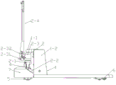
Fig. 1 is a schematic view of the overall structure of an electric hydraulic forklift.
Fig. 2 is a rear view of the electro-hydraulic forklift.
Fig. 3 is a left side view of the electro-hydraulic forklift.
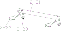
Fig. 4 is a schematic view of a connecting arm assembly.
Fig. 5 is a schematic view of a beam structure.
Fig. 6 is a schematic structural view of the base.
Fig. 7 is a schematic view of a connection structure of the hydraulic cylinder and the second supporting unit.
Fig. 8 is a schematic view of the protective cover structure.
Fig. 9 is a schematic view of the driven wheel structure.
Detailed Description
As shown in fig. 1 to 8, an electro-hydraulic forklift includes: the device comprises a frame 1, a hydraulic lifting unit 2, a driving unit 3, a first supporting unit 1-1, a second supporting unit 4, a pair of driving wheels 5 and two groups of driven wheels 6; one end of the frame 1 along the length direction is a hanging end, and a plurality of driven wheels 6 are arranged at the bottom of the hanging end; the upper surface of the frame 1 is fixedly connected with a storage battery box; the other end of the frame 1 is connected with a hydraulic lifting unit 2; the first supporting unit 1-1 is arranged at the top of the frame 1 and is used for connecting the hydraulic lifting unit 2; the upper lifting top end of the hydraulic lifting unit 2 is connected with the first supporting unit 1-1, and the lower lifting top end is connected with the driving unit 3; the hydraulic lifting unit 2 and the driving unit 3 are connected in a cross way with the driving direction all the time; the second supporting unit 4 comprises a base 4-1 and a supporting rod 4-2, and is used for supporting the hydraulic lifting unit 2, the installation driving unit 3 and the driving wheel 5; the driving unit 3 comprises a motor 3-1 and a differential mechanism 3-2, wherein the motor 3-1 is connected with the differential mechanism 3-2 and is arranged between the driving wheels 5; the power is transmitted by using gears, and the two driving wheels 6 rotate at different speeds when turning.
The hydraulic lifting unit 2 comprises a cross beam 2-1, a connecting arm assembly 2-2, a hydraulic cylinder 2-3 and a hydraulic pressure handle 2-4, and a power control system is arranged at the top end of the hydraulic pressure handle 2-4.
As shown in fig. 2, the hydraulic pressure handle 2-4 comprises a hydraulic upright rod 2-41 and an operating accelerator 2-42, an upright rod hinging seat 2-43 is welded on a cylinder body base 2-31 of the hydraulic cylinder 2-3, and the hydraulic upright rod 2-41 is hinged with the upright rod hinging seat 2-43; the bottom end of the hydraulic vertical rod 2-41 is provided with a cylindrical press shaft 2-44, the top end is provided with a manipulation accelerator 2-42, and the manipulation accelerator 2-42 is connected with the driving unit 3.
As shown in fig. 2, the hydraulic cylinder 2-3 is also provided with a spring assembly 2-32 for controlling the expansion and contraction of the hydraulic cylinder; the spring assembly 2-32 comprises a spring seat 2-321, a spring 2-322 and a spring shaft 2-323; the spring seats 2-321 are arranged right below the vertical rods 7-1, and the spring seats 2-321 are fixedly connected with the cylinder body bases 2-31 through connecting pieces; the bottom end of the spring 2-322 is fixedly connected with the spring seat 2-321, the top of the spring 2-322 is fixedly connected with the vertical pressure rod 2-323, the hydraulic rod 2-323 is installed in a sliding fit with the spring seat 2-321, and the top end of the hydraulic rod is tightly pressed on the lower part of the cylindrical pressure shaft 2-44; when the upright rod 2-41 is rotated, the cylindrical pressure shaft 2-44 presses the vertical pressure rod 2-323, the spring 7-4 contracts, and the hydraulic cylinder 2-3 is controlled to lift.
As shown in fig. 5, the cross beam 2-1 is positioned at the bottom of a hydraulic near-term 2-3, and connecting claws are arranged at two ends of the cross beam and hinged with a connecting arm component 2-2; the connecting arm assembly 2-2 comprises a rotating shaft 2-21 rotatably connected with the frame 1, and a long connecting arm 2-22 and a short connecting arm 2-23 fixedly connected at two ends of the rotating shaft 2-21, wherein the long connecting arm 2-22 and the short connecting arm 2-23 are arranged at an included angle of 90 degrees, the long connecting arm 2-22 is hinged with the cross beam 2-1, and the short connecting arm 2-23 is hinged with a lifting adjusting pull rod 6-1 of the driven wheel 6; the fixed end of the hydraulic cylinder 2-3 is connected with the supporting rod 4-2, and the supporting rod 4-2 penetrates through a mounting hole in the middle of the cross beam 2-1 to be connected with the base 4-1; the movable end of the hydraulic cylinder 2-3 is connected with the first supporting unit 1-1.
As shown in fig. 8, the forklift is further provided with a protective cover 7, the protective cover 7 is installed outside the driving unit 3, and the top and two sides of the protective cover 8 are respectively provided with a connecting piece with holes and connected with the cross beam 2-1 and the frame 1 through bolts.
As shown in fig. 6, the middle of the base 4-1 is provided with a shaft hole 4-11, the inner side wall of the shaft hole 4-11 is symmetrically provided with a vertical boss 4-12, the boss 4-12 is provided with a pin hole 4-13, and two sides of the base 4-1 are symmetrically provided with bearing flanges 4-14 for mounting a driving wheel 5; the central connecting line between the bosses 4-12 is vertical to the connecting line between the bearing flanges 4-14 on the horizontal plane.
The differential mechanism 3-2 controls the rotating speed and braking of the power driving wheel 5, so that the forklift can carry goods; the hydraulic handle controls the hydraulic lifting unit 2 to lift; and the hydraulic cylinder 2-3 is used for extending and contracting the top column through a hydraulic handle and controlling the lifting of the frame 1. The battery box 1-2 has large space and can be loaded with a plurality of batteries and a controller; the cross beam has large span and supports the lifting of the load materials of the whole vehicle; the base is connected with a hydraulic cylinder power system and supports and guides; the protective cover protects the motor and the driving wheel; the connecting arm is used for connecting the cross beam and the driven wheel adjusting pull rod; a baffle is arranged at the rear side of the battery box 1-2 and is used for sealing the battery box, protecting the battery and the controller; the baffle is provided with a power switch, a charging socket and an outlet; the driving unit 3 utilizes a gear to reduce speed for transmission, and the two driving wheels can run at different speeds during turning to stabilize the speed; the driving wheel is directly driven to run by the gearbox through the transmission shaft; the driven wheel assembly lifts, supports and carries the goods, and the resistance is reduced through the driven operation.
And a control knob and a safety emergency stop button are arranged on the hydraulic pressure handles 2-4.
The above description is only a preferred embodiment of the present invention, and does not limit the present invention in any way. It will be understood by those skilled in the art that various changes, substitutions and alterations can be made herein without departing from the spirit and scope of the invention as defined by the appended claims.
Claims (7)
1. An electric hydraulic forklift is characterized by comprising a frame, a hydraulic lifting unit, a driving unit, a first supporting unit, a second supporting unit, a pair of driving wheels and two groups of driven wheels; one end of the frame in the length direction is a hanging end, and a plurality of driven wheels are arranged at the bottom of the hanging end; the upper surface of the frame is fixedly connected with the storage battery box; the other end of the frame is connected with a hydraulic lifting unit; the first supporting unit is arranged at the top of the frame and is used for connecting the hydraulic lifting unit; the upper lifting top end of the hydraulic lifting unit is connected with the first supporting unit, and the lower lifting top end of the hydraulic lifting unit is connected with the driving unit; the hydraulic lifting unit and the driving unit are connected in a cross manner with the driving direction all the time; the second supporting unit comprises a base and a supporting rod and is used for supporting the hydraulic lifting unit, installing the driving unit and the driving wheel; the driving unit comprises a motor and a differential mechanism, and the motor is connected with the differential mechanism and is arranged between the driving wheels; the power is transmitted by using gears, and the two driving wheels rotate at different speeds during turning.
2. The electro-hydraulic forklift as recited in claim 1, wherein the hydraulic lifting unit comprises a cross beam, a connecting arm assembly, a hydraulic cylinder and a hydraulic pressure handle, and a power control system is arranged at the top end of the hydraulic pressure handle.
3. The electro-hydraulic forklift as claimed in claim 2, wherein the hydraulic pressure handle comprises a hydraulic upright and a steering accelerator, an upright hinge seat is welded on a cylinder body base of the hydraulic cylinder, and the hydraulic upright is hinged with the upright hinge seat; the bottom end of the hydraulic vertical rod is provided with a cylindrical pressing shaft, and the top end of the hydraulic vertical rod is provided with a control accelerator which is connected with a driving unit.
4. An electro-hydraulic forklift as claimed in claim 2, wherein the hydraulic cylinder is further provided with a spring assembly for controlling the extension and retraction thereof; the spring assembly comprises a spring seat, a spring and a spring shaft; the spring seat is arranged right below the vertical rod and is fixedly connected with the cylinder body base through a connecting piece; the bottom end of the spring is fixedly connected with the spring seat, the top of the spring is fixedly connected with the vertical pressure rod, the hydraulic rod is installed in sliding fit with the spring seat, and the top end of the hydraulic rod is tightly pressed on the lower part of the cylindrical pressure shaft; when the vertical rod is rotated, the cylindrical pressing shaft presses the vertical pressing rod downwards, the spring contracts, and the hydraulic cylinder is controlled to lift.
5. The electro-hydraulic forklift as claimed in claim 2, wherein the cross beam is located at the bottom of the hydraulic near-term inner bottom, and connecting claws are arranged at two ends of the cross beam and hinged with the connecting arm assembly; the connecting arm assembly comprises a rotating shaft rotatably connected with the frame, and a long connecting arm and a short connecting arm which are fixedly connected to two ends of the rotating shaft, wherein the long connecting arm and the short connecting arm are arranged at an included angle, the long connecting arm is hinged with the cross beam, and the short connecting arm is hinged with a lifting adjusting pull rod of the driven wheel; the fixed end of the hydraulic cylinder is connected with a support rod, and the support rod penetrates through a mounting hole in the middle of the cross beam and is connected with the base; the movable end of the hydraulic cylinder is connected with the first supporting unit.
6. The electro-hydraulic forklift as claimed in claim 1, wherein the forklift is further provided with a protective cover, the protective cover is mounted outside the driving unit, and the top and both sides of the protective cover are respectively provided with a connecting piece with holes and connected with the cross beam and the frame through bolts.
7. The electro-hydraulic forklift as claimed in claim 1, wherein a shaft hole is formed in the middle of the base, vertical bosses are symmetrically arranged on the inner side walls of the shaft hole, pin holes are formed in the bosses, and bearing flanges are symmetrically arranged on two sides of the base and used for mounting a driving wheel; the center connecting line between the bosses is vertical to the connecting line between the bearing flanges on the horizontal plane.
Priority Applications (1)
| Application Number | Priority Date | Filing Date | Title |
|---|---|---|---|
| CN201911405444.2A CN110844842A (en) | 2019-12-30 | 2019-12-30 | Electric hydraulic forklift |
Applications Claiming Priority (1)
| Application Number | Priority Date | Filing Date | Title |
|---|---|---|---|
| CN201911405444.2A CN110844842A (en) | 2019-12-30 | 2019-12-30 | Electric hydraulic forklift |
Publications (1)
| Publication Number | Publication Date |
|---|---|
| CN110844842A true CN110844842A (en) | 2020-02-28 |
Family
ID=69610763
Family Applications (1)
| Application Number | Title | Priority Date | Filing Date |
|---|---|---|---|
| CN201911405444.2A Withdrawn CN110844842A (en) | 2019-12-30 | 2019-12-30 | Electric hydraulic forklift |
Country Status (1)
| Country | Link |
|---|---|
| CN (1) | CN110844842A (en) |
Cited By (2)
| Publication number | Priority date | Publication date | Assignee | Title |
|---|---|---|---|---|
| CN114506379A (en) * | 2022-04-19 | 2022-05-17 | 江苏盈彩纺织科技有限公司 | Weaving winding up roller strorage device with high protectiveness |
| CN115872323A (en) * | 2021-09-27 | 2023-03-31 | 广西大学 | A suspended two-wheel differential electric forklift |
-
2019
- 2019-12-30 CN CN201911405444.2A patent/CN110844842A/en not_active Withdrawn
Cited By (2)
| Publication number | Priority date | Publication date | Assignee | Title |
|---|---|---|---|---|
| CN115872323A (en) * | 2021-09-27 | 2023-03-31 | 广西大学 | A suspended two-wheel differential electric forklift |
| CN114506379A (en) * | 2022-04-19 | 2022-05-17 | 江苏盈彩纺织科技有限公司 | Weaving winding up roller strorage device with high protectiveness |
Similar Documents
| Publication | Publication Date | Title |
|---|---|---|
| CN201125140Y (en) | Electric mechanical loading and unloading forklift | |
| CN105152036A (en) | Electric transportation trolley for automatic glass mounting | |
| CN201702777U (en) | Cantilever type assistance mechanical arm | |
| CN105174140A (en) | Power control assembly of electric tray conveying vehicle and electric conveying vehicle | |
| CN204497630U (en) | A kind of highly compatible for circuit breaker and porcelain vase overturns car | |
| CN110154862B (en) | Full-steering explosion-proof storage battery transfer trolley | |
| CN102935800A (en) | Self-walking scissors fork type lift platform | |
| CN109969983A (en) | A kind of lift carrier | |
| CN212246091U (en) | Electric hydraulic forklift | |
| CN102408081B (en) | Multifunctional electric hoist for indoor hoisting and transporting | |
| CN102267439A (en) | Battery quick-change device for electric automobile | |
| KR101519473B1 (en) | Apparatus for towing apparatus | |
| CN211644507U (en) | Adjustable forklift | |
| CN204454333U (en) | Wind-power tower manufactures special crawler belt suspension transferring machine | |
| CN204675648U (en) | A kind of portal frame hoisting crane automatically | |
| CN103288009A (en) | Small electric forklift | |
| CN202609860U (en) | Container shifter special for container | |
| CN215798067U (en) | Small crane convenient to load | |
| CN202785547U (en) | Vertical column type lifting platform capable of self walking | |
| CN102849661A (en) | Self-propelled vertical column type lifting platform | |
| CN209740583U (en) | Mobile lifting type manual carrier | |
| CN210116654U (en) | An electric small aircraft rodless tractor | |
| CN113991494A (en) | Transformer substation grounding wire moving platform | |
| CN202609892U (en) | Automatic rolling tipper for steel coils | |
| CN205574024U (en) | Electronic hydraulic pressure carrier |
Legal Events
| Date | Code | Title | Description |
|---|---|---|---|
| PB01 | Publication | ||
| PB01 | Publication | ||
| SE01 | Entry into force of request for substantive examination | ||
| SE01 | Entry into force of request for substantive examination | ||
| WW01 | Invention patent application withdrawn after publication |
Application publication date: 20200228 |
|
| WW01 | Invention patent application withdrawn after publication |