CN110839401A - End effector for Chinese cabbage harvesting machine - Google Patents
End effector for Chinese cabbage harvesting machine Download PDFInfo
- Publication number
- CN110839401A CN110839401A CN201911147823.6A CN201911147823A CN110839401A CN 110839401 A CN110839401 A CN 110839401A CN 201911147823 A CN201911147823 A CN 201911147823A CN 110839401 A CN110839401 A CN 110839401A
- Authority
- CN
- China
- Prior art keywords
- end effector
- rotary cutter
- chinese cabbage
- lead screw
- rotating shaft
- Prior art date
- Legal status (The legal status is an assumption and is not a legal conclusion. Google has not performed a legal analysis and makes no representation as to the accuracy of the status listed.)
- Pending
Links
Images


Classifications
-
- A—HUMAN NECESSITIES
- A01—AGRICULTURE; FORESTRY; ANIMAL HUSBANDRY; HUNTING; TRAPPING; FISHING
- A01D—HARVESTING; MOWING
- A01D45/00—Harvesting of standing crops
- A01D45/26—Harvesting of standing crops of cabbage or lettuce
Abstract
The invention relates to an end effector for a Chinese cabbage harvesting machine, which belongs to the field of agricultural machinery and comprises two brackets, a position adjusting device, a power device and a collecting device, wherein the two brackets are arranged in parallel relatively; the position adjusting device comprises a longitudinal slideway, a transverse slideway and a hydraulic system; the power device is arranged at the top end of the bracket; the power device comprises a lead screw, a coupler and a lead screw motor; the lead screw extends downwards from the top end to the bottom end; the coupler and the lead screw motor are positioned at the top end of the lead screw; the collecting device comprises a rotary cutter, a rotating shaft, a bearing seat and a rotary cutter motor; the rotary cutter motor is arranged at the bottom end of the lead screw and is connected with the rotating shaft through a bearing seat; the rotating shaft is positioned between the two brackets and is vertical to the screw rod; the rotary cutter is arranged on the rotating shaft and rotates along with the rotating shaft in the same direction. The end effector is inserted into soil at the root of the Chinese cabbage by adopting two sharp teeth, and the Chinese cabbage is pulled up by overturning, so that the damage to the Chinese cabbage is reduced to the maximum extent.
Description
Technical Field
The invention belongs to the technical field of agricultural equipment, and particularly relates to a Chinese cabbage harvesting machine.
Background
Chinese cabbage is one of the vegetables which have large planting area and are eaten more. Especially, the reserves of cabbage in winter in northern areas are large. Chinese cabbage belongs to the head-forming leaf vegetable, and the whole process from sowing to harvesting accounts for more than half of the total labor amount, so that the labor intensity is high, and the labor cost is high. At present, due to the planting amount of vegetable growers, the high price and the unstable operation of a Chinese cabbage harvesting machine, most of the Chinese cabbage harvesting field adopts manual harvesting, the Chinese cabbage needs to be stooped over for a long time during harvesting to be pulled out, picked up, carried and the like, the labor intensity is very high, and a large amount of manpower and material resources are consumed.
At present, most of end effectors of the Chinese cabbage harvesters adopt annular belts which rotate oppositely to directly contact with the Chinese cabbage bodies and pull out the Chinese cabbage bodies by virtue of friction, the harvesting modes are very easy to damage the surfaces of the Chinese cabbage, so that the Chinese cabbage is rotten, the yield and the quality are reduced, and the integrated Chinese cabbage harvesters are expensive and cannot be born by common vegetable growers; in addition, the Chinese cabbages are righted and clamped by the clamping mechanisms with symmetrical sides, the roots of the Chinese cabbages are cut off by the high-speed rotating disc cutters which are symmetrically arranged, the Chinese cabbages are easily damaged in the root cutting process due to uneven growth of the Chinese cabbages, the rotting of the Chinese cabbages is affected, the economic value of the Chinese cabbages is affected, and the Chinese cabbage roots left in the field need to be subjected to secondary treatment, so that time and labor are wasted.
Disclosure of Invention
In order to solve the defects in the prior art, the invention aims to provide an end effector for a Chinese cabbage harvesting machine, which is improved in that two sharp teeth are inserted into soil at the root of a Chinese cabbage, the Chinese cabbage is pulled up by overturning, the Chinese cabbage is pulled up by adopting a linear motion mode until the Chinese cabbage is contacted, and the damage to the Chinese cabbage is reduced to the maximum extent by pulling up the Chinese cabbage.
In order to achieve the purpose, the invention adopts the specific scheme that:
an end effector for a cabbage harvesting machine, the end effector being connected to the cabbage harvesting machine; the end effector comprises two brackets, a position adjusting device, a power device and a collecting device which are arranged in parallel relatively; the position adjusting device is arranged on the outer side of the bracket; the position adjusting device comprises a longitudinal slideway, a transverse slideway in sliding connection with the longitudinal slideway through a movable sliding block and a hydraulic system; the power device is arranged at the top end of the bracket; the power device comprises a lead screw, a coupler and a lead screw motor; the lead screw extends downwards from the top end to the bottom end; the coupler and the lead screw motor are positioned at the top end of the lead screw;
the collecting device comprises a rotary cutter, a rotating shaft, a bearing seat and a rotary cutter motor; the rotary cutter motor is arranged at the bottom end of the lead screw and is connected with the rotating shaft through a bearing seat; the rotating shaft is positioned between the two brackets and is vertical to the screw rod;
the rotary cutter comprises a baffle and an insertion part positioned at the end of the baffle; the insertion part consists of two sharp teeth which are arranged at intervals; the rotary cutter is arranged on the rotating shaft and rotates along the same direction of the rotating shaft;
as a further optimization of the above solution, the end effector further comprises a transmission device, and the transmission device is located at the rear end of the end effector; the conveying device comprises a conveying belt, belt wheels positioned at two ends of the conveying belt and a motor for driving the belt wheels to rotate; the conveyor belt is positioned between the two brackets and below the rotary cutter; the belt wheel is parallel to the rotating shaft.
As a further optimization of the above scheme, the rotary cutter comprises a baffle plate, and an upper insertion part and a lower insertion part which are positioned at two ends of the baffle plate, wherein the upper insertion part and the lower insertion part are both perpendicular to the baffle plate and extend in opposite directions.
As a further optimization of the scheme, the end effector is connected with the Chinese cabbage harvesting machine through the suspension part.
The invention has the advantages that:
(1) the Chinese cabbage harvesting is carried out by adopting the insertion and rolling type matching technology for the first time, the complex control degree of the harvesting machine is reduced, the manufacturing cost is low, and the maintenance is convenient.
(2) The device can be matched with a tractor for use, and is conveyed to a designated collecting device through a conveying belt for collection, or only Chinese cabbage and land can be separated and collected in addition.
(3) The harvesting device is directly inserted into the soil on two sides of the root and is not in direct contact with the Chinese cabbage, so that the damage of a mechanical device to the Chinese cabbage is avoided.
Has the advantages that:
the Chinese cabbage harvesting machine performs Chinese cabbage harvesting in a mode of matching insertion and turnover, has a simple mechanical structure, is low in manufacturing cost, is convenient to maintain, and is more acceptable to vegetable growers. The device can be matched with the conveying belt to effectively collect the Chinese cabbages, can also omit conveying and only pile the Chinese cabbages and the land separation belt in situ, and vegetable growers can select a collection mode as required. The harvesting device is not in direct contact with the Chinese cabbages, avoids damage to the Chinese cabbages, and is beneficial to the transportation and storage of the Chinese cabbages.
Drawings
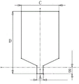
FIG. 1 is a cabbage-like drawing; in the figure, A represents the diameter of the root of the Chinese cabbage, B represents the depth of the root into the soil, C represents the width of the Chinese cabbage body, and D represents the overall height;
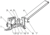
FIG. 2 is a view showing the overall assembly structure of the end effector described in embodiment 1;
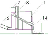
FIG. 3 is a side view of the end effector of example 1 as it begins harvesting;
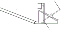
FIG. 4 is a side view of a cabbage when inverted using the end effector described in example 1;
FIG. 5 is a side view of the end effector of example 1 used to slide cabbage; wherein E is 200 mm;
FIG. 6 is a side view of the return knife after the cabbage has been collected by the end effector of example 1;
FIG. 7 is a view showing the overall assembly structure of the end effector described in embodiment 2;
in the figure: 1. rotating a cutter; 2. a rotating shaft; 3. a lead screw; 4. a coupling; 5. a wire cylinder motor; 6. a conveyor belt; 7. a suspension member; 8. a longitudinal slideway; 9. moving the slide block; 10. a transverse slideway; 11. a support; 12. a rotary cutter motor; 13. a bearing seat; 14. chinese cabbage.
Detailed Description
The technical solutions in the embodiments of the present invention will be clearly and completely described below with reference to the embodiments of the present invention.
Example 1
An end effector for a cabbage harvesting machine, the cabbage harvesting machine being a tractor; the end effector is connected with the tractor through a suspension component 7; and the hanging part 7 is provided with a screw hole, and the hanging part 7 is fixed on the tractor through the matching of the screw hole and a bolt.
The end effector comprises two brackets 11 (a bracket I and a bracket II) which are arranged in parallel relatively, a position adjusting device, a power device and a collecting device;
the position adjusting device comprises a longitudinal slideway 8, a transverse slideway 10 and a hydraulic system; the longitudinal slideway 8 is connected with the suspension part 7 in a sliding way; the transverse slide way 10 is vertical to and connected with the longitudinal slide way 8 in a sliding way through a movable slide block 9; when the device works, the working position of the device can be adjusted through the longitudinal slide way 8 and the transverse slide way 10, and power can be driven by a hydraulic system.
The position adjusting device is arranged on the outer side of the bracket 11; one end of the transverse slideway 10 is fixedly connected with the bracket I, and the other end of the transverse slideway extends in the direction far away from the bracket II;
the power devices are respectively arranged at the top ends of the brackets 11; the power device comprises a lead screw 3, a coupler 4 and a lead screw motor 5; the lead screw 3 is obliquely arranged and extends downwards from the top end to the bottom end; the coupler 4 and the lead screw motor 5 are positioned at the top end of the lead screw 3; the bottom end of the lead screw 3 is connected with a collecting device.
The collecting device comprises a rotary cutter 1, a rotating shaft 2, a bearing seat 13 and a rotary cutter motor 12; the rotary cutter motor 12 is arranged at the bottom end of the screw rod 3 and is connected with the rotating shaft 2 through a bearing seat 13; the rotating shaft 2 is positioned between the two brackets 11 and is vertical to the screw rod 3;
the rotary cutter 1 comprises a baffle, an upper insertion part and a lower insertion part, wherein the upper insertion part and the lower insertion part are positioned at two ends of the baffle, the upper insertion part and the lower insertion part are both vertical to the baffle and opposite in extension direction, and the upper insertion part and the lower insertion part are both composed of two sharp teeth arranged at intervals; the rotary cutter 1 is arranged on the rotating shaft 2 and rotates along with the rotating shaft 2 in the same direction between the two brackets 11.
The end effector further comprises a transmission device, and the transmission device is positioned at the rear end of the end effector; the conveying device comprises a conveying belt 6, belt wheels positioned at two ends of the conveying belt 6 and a motor for driving the belt wheels to rotate in the same direction; the conveyor belt 6 is positioned between the two brackets 11 and below the rotary cutter 1; the belt wheel is parallel to the rotating shaft 2. One end of the conveying belt 6 is connected with the bottom of the rear part of the support 11 through a belt wheel, and the other end of the conveying belt extends to a designated cabbage collecting position.
As shown in figure 1, the diameter (A) of the root of the Chinese cabbage is about 40-60mm, the depth (B) of the root of the Chinese cabbage is about 50mm, the width (C) of the main body of the Chinese cabbage is about 200-400mm, and the overall height (D) of the Chinese cabbage is about 350-500 mm.
Before the start of work, the rotary cutter 1 is in a horizontal position and is positioned at the bottom end of the screw rod 3, the tractor drives the end effector to move forward, the rotary cutter 1 cannot rotate at the moment, two sharp teeth of the rotary cutter 1 are inserted into two sides of the root of the Chinese cabbage 14, and the direct contact with the body of the Chinese cabbage 14 is avoided, as shown in figure 3.
When the cabbage 14 abuts against the baffle on the vertical surface of the rotary cutter 1, the rotary cutter 1 is turned upwards, and simultaneously the lead screw motor 5 drives the lead screw 3 to rotate, so as to drive the rotary cutter 1 to move upwards, and the rotation and the movement of the rotary cutter 1 are simultaneously carried out, as shown in fig. 4.
When the rotary knife 1 moves upwards by 200mm, the rotary knife 1 rotates by an angle enough to enable the Chinese cabbage 14 to naturally slide down by means of gravity and directly slide on the conveyor belt 6, as shown in fig. 5.
After the cabbage 14 slides down, the rotary cutter 1 continues to rotate, meanwhile, the lead screw motor 5 rotates reversely to drive the lead screw 3 to rotate, and the rotary cutter 1 moves downwards until the two sharp teeth of the rotary cutter 1 are horizontal and move to the bottommost end of the lead screw 3, as shown in fig. 6 and 2.
Example 2
The structure is substantially the same as that of embodiment 1, except that a conveying device is not provided, as shown in fig. 7. The Chinese cabbage naturally slides down by gravity and directly falls on the ground, and the harvested Chinese cabbage is spread on the ground and then collected for the second time.
In summary, compared with the prior art, the end effector of the present invention has the following differences and advantages:
(1) the existing Chinese cabbage harvesting machine is a large-scale complete machine with a complicated mechanical structure or a harvesting operation machine matched with a tractor, is expensive and inconvenient to maintain, and cannot be borne by common vegetable growers; the invention can be hung by tractors of various types in front, has simplified structure and low cost, and is easy to be widely accepted by vegetable growers;
(2) the existing Chinese cabbage harvesting machines mostly adopt the way that double rollers rotate oppositely, the Chinese cabbage is held and pulled up and then is conveyed into a conveying belt, certain mechanical damage is caused to the Chinese cabbage, the rotting of the Chinese cabbage is accelerated, and the Chinese cabbage harvesting machines are not beneficial to transportation and storage; according to the invention, the two shovels extend to the two sides of the rhizome and are then turned over to be pulled up, so that the damage to the Chinese cabbage is reduced to the minimum extent;
(3) the existing partial Chinese cabbage harvesting machine cuts the root of the Chinese cabbage and then harvests the Chinese cabbage, so that the surface of the Chinese cabbage is easily damaged, and the Chinese cabbage root is left in soil to be subjected to secondary treatment, which wastes time and labor; the invention can pull up the Chinese cabbage with roots, thereby saving the process of cutting the roots and reducing the trouble of soil preparation.
It should be noted that the above-mentioned embodiments illustrate rather than limit the scope of the invention, which is defined by the appended claims. It will be apparent to those skilled in the art that certain insubstantial modifications and adaptations of the present invention can be made without departing from the spirit and scope of the invention.
Claims (4)
1. The utility model provides an end effector for chinese cabbage harvesting machinery, end effector is connected with chinese cabbage harvesting machinery which characterized in that: the end effector comprises two brackets (11) which are arranged in parallel relatively, a position adjusting device, a power device and a collecting device; the position adjusting device is arranged on the outer side of the bracket (11); the position adjusting device comprises a longitudinal slideway (8), a transverse slideway (8) and a hydraulic system, wherein the transverse slideway (8) is connected with the longitudinal slideway (8) in a sliding manner through a movable sliding block (9); the power device is arranged at the top end of the bracket (11); the power device comprises a lead screw (3), a coupler (4) and a lead screw motor (5); the screw rod (3) extends downwards from the top end to the bottom end; the coupler (4) and the lead screw motor (5) are positioned at the top end of the lead screw (3);
the collecting device comprises a rotary cutter (1), a rotating shaft (2), a bearing seat (13) and a rotary cutter motor (12); the rotary cutter motor (12) is arranged at the bottom end of the lead screw (3) and is connected with the rotating shaft (2) through a bearing seat (13); the rotating shaft (2) is positioned between the two brackets (11) and is vertical to the screw rod (3);
the rotary cutter (1) comprises a baffle and an insertion part positioned at the end of the baffle; the insertion part consists of two sharp teeth which are arranged at intervals; the rotary cutter (1) is arranged on the rotating shaft (2) and rotates along with the rotating shaft (2) in the same direction.
2. The end effector for a cabbage harvesting machine as claimed in claim 1, wherein: the end effector further comprises a transmission device, and the transmission device is positioned at the rear end of the end effector; the conveying device comprises a conveying belt (6), belt wheels positioned at two ends of the conveying belt (6) and a motor for driving the belt wheels to rotate in the same direction; the conveyor belt (6) is positioned between the two brackets (11) and below the rotary cutter (1); the belt wheel is parallel to the rotating shaft (2).
3. The end effector for a cabbage harvesting machine as claimed in claim 1, wherein: the rotary cutter (1) comprises a baffle, an upper insertion part and a lower insertion part, wherein the upper insertion part and the lower insertion part are positioned at two ends of the baffle, and the upper insertion part and the lower insertion part are perpendicular to the baffle and opposite in extension direction.
4. The end effector for a cabbage harvesting machine as claimed in claim 1, wherein: the end effector is connected with a Chinese cabbage harvesting machine through a suspension part (7).
Priority Applications (1)
| Application Number | Priority Date | Filing Date | Title |
|---|---|---|---|
| CN201911147823.6A CN110839401A (en) | 2019-11-21 | 2019-11-21 | End effector for Chinese cabbage harvesting machine |
Applications Claiming Priority (1)
| Application Number | Priority Date | Filing Date | Title |
|---|---|---|---|
| CN201911147823.6A CN110839401A (en) | 2019-11-21 | 2019-11-21 | End effector for Chinese cabbage harvesting machine |
Publications (1)
| Publication Number | Publication Date |
|---|---|
| CN110839401A true CN110839401A (en) | 2020-02-28 |
Family
ID=69603155
Family Applications (1)
| Application Number | Title | Priority Date | Filing Date |
|---|---|---|---|
| CN201911147823.6A Pending CN110839401A (en) | 2019-11-21 | 2019-11-21 | End effector for Chinese cabbage harvesting machine |
Country Status (1)
| Country | Link |
|---|---|
| CN (1) | CN110839401A (en) |
Cited By (2)
| Publication number | Priority date | Publication date | Assignee | Title |
|---|---|---|---|---|
| CN112262654A (en) * | 2020-10-28 | 2021-01-26 | 付书勇 | Aquatic plant pulling-out device |
| CN113396726A (en) * | 2021-05-25 | 2021-09-17 | 河南科技大学 | Intelligent profile modeling stripping device for hydroponic lettuce and yellow rotten vegetable leaves |
-
2019
- 2019-11-21 CN CN201911147823.6A patent/CN110839401A/en active Pending
Cited By (3)
| Publication number | Priority date | Publication date | Assignee | Title |
|---|---|---|---|---|
| CN112262654A (en) * | 2020-10-28 | 2021-01-26 | 付书勇 | Aquatic plant pulling-out device |
| CN113396726A (en) * | 2021-05-25 | 2021-09-17 | 河南科技大学 | Intelligent profile modeling stripping device for hydroponic lettuce and yellow rotten vegetable leaves |
| CN113396726B (en) * | 2021-05-25 | 2022-09-13 | 河南科技大学 | Intelligent profile modeling stripping device for hydroponic lettuce and yellow rotten vegetable leaves |
Similar Documents
| Publication | Publication Date | Title |
|---|---|---|
| CN202603210U (en) | Common head cabbage harvester | |
| CN101444161B (en) | Cotton stalk puller | |
| CN110679271B (en) | Potato seedling ensiling header and self-propelled potato seedling ensiling harvester | |
| CN210537461U (en) | Sweet potato stem leaf harvester | |
| CN110839401A (en) | End effector for Chinese cabbage harvesting machine | |
| CN110622691A (en) | Sugarcane is reaped and is ploughed fertilization all-in-one of hiding | |
| CN112005695A (en) | Garlic combine harvester | |
| CN110859082A (en) | Towed big and small row garlic combine harvester | |
| CN103168555B (en) | Drawing device of bulb-class vegetable harvesting machine | |
| CN203327552U (en) | Guide soil brushing device of cabbage vegetable harvester | |
| CN102027838B (en) | Round disc type plant straw uprooting device | |
| CN212087040U (en) | End effector for Chinese cabbage harvesting machine | |
| CN204929635U (en) | Garlic combined harvester | |
| CN209882579U (en) | Sugarcane cutting auxiliary machine | |
| CN116762563A (en) | Self-propelled cabbage harvester | |
| CN110999630A (en) | Vegetable harvester capable of harvesting vegetables with roots | |
| CN111083983A (en) | Full-automatic potato harvester | |
| CN203327543U (en) | Conveying and cutting device cabbage vegetable harvester | |
| CN210537524U (en) | Cutting and conveying device of sweet potato stem leaf harvester | |
| CN211378807U (en) | Towed big and small row garlic combine harvester | |
| CN210868804U (en) | Sugarcane is reaped and is ploughed fertilization all-in-one of hiding | |
| CN103250500A (en) | Guide soil-brushing device of head vegetable harvesting machine | |
| CN209861607U (en) | Self-propelled combined harvester for vegetable heads | |
| CN204669889U (en) | Handpiece structure and comprise the hot pickled mustard tube grain header of handpiece structure | |
| CN214338489U (en) | Soil loosening device for agricultural planting |
Legal Events
| Date | Code | Title | Description |
|---|---|---|---|
| PB01 | Publication | ||
| PB01 | Publication | ||
| SE01 | Entry into force of request for substantive examination | ||
| SE01 | Entry into force of request for substantive examination |