CN110820484A - Intelligence road surface burnishing machine - Google Patents
Intelligence road surface burnishing machine Download PDFInfo
- Publication number
- CN110820484A CN110820484A CN201911122920.XA CN201911122920A CN110820484A CN 110820484 A CN110820484 A CN 110820484A CN 201911122920 A CN201911122920 A CN 201911122920A CN 110820484 A CN110820484 A CN 110820484A
- Authority
- CN
- China
- Prior art keywords
- sleeve
- road surface
- bolt
- welded
- battery box
- Prior art date
- Legal status (The legal status is an assumption and is not a legal conclusion. Google has not performed a legal analysis and makes no representation as to the accuracy of the status listed.)
- Withdrawn
Links
- 238000003860 storage Methods 0.000 claims abstract description 20
- 238000003466 welding Methods 0.000 claims description 16
- 238000007789 sealing Methods 0.000 claims description 8
- 241000883990 Flabellum Species 0.000 claims description 7
- 230000008859 change Effects 0.000 claims description 3
- 238000005498 polishing Methods 0.000 abstract description 26
- 230000001681 protective effect Effects 0.000 abstract description 8
- 238000010276 construction Methods 0.000 abstract 1
- 230000032258 transport Effects 0.000 description 6
- 235000017166 Bambusa arundinacea Nutrition 0.000 description 5
- 235000017491 Bambusa tulda Nutrition 0.000 description 5
- 241001330002 Bambuseae Species 0.000 description 5
- 235000015334 Phyllostachys viridis Nutrition 0.000 description 5
- 239000011425 bamboo Substances 0.000 description 5
- 230000006378 damage Effects 0.000 description 5
- 239000000428 dust Substances 0.000 description 4
- 238000007790 scraping Methods 0.000 description 4
- 238000010586 diagram Methods 0.000 description 3
- 238000005096 rolling process Methods 0.000 description 3
- 230000009286 beneficial effect Effects 0.000 description 2
- 230000005540 biological transmission Effects 0.000 description 2
- 238000001816 cooling Methods 0.000 description 2
- 230000007613 environmental effect Effects 0.000 description 2
- 230000007547 defect Effects 0.000 description 1
- 230000000694 effects Effects 0.000 description 1
- 238000005516 engineering process Methods 0.000 description 1
- 238000001914 filtration Methods 0.000 description 1
- 230000036541 health Effects 0.000 description 1
- 238000012423 maintenance Methods 0.000 description 1
- 238000004519 manufacturing process Methods 0.000 description 1
- 238000000034 method Methods 0.000 description 1
- 230000008569 process Effects 0.000 description 1
- 210000000707 wrist Anatomy 0.000 description 1
Images


Classifications
-
- E—FIXED CONSTRUCTIONS
- E01—CONSTRUCTION OF ROADS, RAILWAYS, OR BRIDGES
- E01C—CONSTRUCTION OF, OR SURFACES FOR, ROADS, SPORTS GROUNDS, OR THE LIKE; MACHINES OR AUXILIARY TOOLS FOR CONSTRUCTION OR REPAIR
- E01C19/00—Machines, tools or auxiliary devices for preparing or distributing paving materials, for working the placed materials, or for forming, consolidating, or finishing the paving
- E01C19/22—Machines, tools or auxiliary devices for preparing or distributing paving materials, for working the placed materials, or for forming, consolidating, or finishing the paving for consolidating or finishing laid-down unset materials
- E01C19/42—Machines for imparting a smooth finish to freshly-laid paving courses other than by rolling, tamping or vibrating
Landscapes
- Engineering & Computer Science (AREA)
- Architecture (AREA)
- Civil Engineering (AREA)
- Structural Engineering (AREA)
- Grinding-Machine Dressing And Accessory Apparatuses (AREA)
Abstract
The invention provides an intelligent road surface polishing machine, which comprises a sleeve, a storage battery box and a protective ring, wherein the protective ring is arranged on the outer side of the sleeve, the storage battery box is welded at the top of the sleeve, a first bearing is sleeved on the outer side of the sleeve, a support rod is welded on the outer side of the first bearing, a rubber ring is bonded on the outer side of the protective ring, a filter cylinder is arranged on one side of the sleeve, an air hole is formed in the outer wall of the sleeve, a rotating plate is arranged on one side of the sleeve, a support rod is welded on one side of the rotating plate, a grab handle is welded at the top end of the support rod, a switch is arranged on the grab handle through a bolt, a screw hole is formed in the storage battery box, a connecting bolt is arranged on the inner side of the screw hole, a motor is arranged on the inner side of the sleeve through a bolt, a main, the polishing and grinding device is suitable for polishing and grinding the pavement in the later stage of road construction.
Description
Technical Field
The invention relates to the field of road surface polishing machines, in particular to an intelligent road surface polishing machine.
Background
The ground polishing is a process of changing a rough and monotonous concrete surface into an elegant and durable terrace, the concrete surface is ground and polished by using a high-speed and high-power polishing machine, the existing road polishing machine has the advantages of reasonable structure, safety and reliability, mainstream products, low cost, low maintenance amount, high polishing speed, good polishing quality, convenient use, convenient operation and the like, and can meet the use requirement of the existing road polishing, however, for most road polishing machines, on one hand, when in work, once a person takes off the handle due to hand slip or other reasons, the polishing machine body is easy to rotate under the driving of a motor, the polishing machine is easy to be out of control, the polishing machine cannot be closed quickly so as to possibly cause equipment or road damage, and the operation safety is not beneficial to guarantee, on the other hand, when polishing operation is carried out again, produce a large amount of dusts easily, and then can cause the protective pollution, harm personnel's health, and the motor produces the life that high temperature influences the motor easily for long-time work, on the one hand again, when removing, need all vehicles or manpower to transport it to the work place, because the road surface is not completely hardened yet, the vehicle transports and causes stress damage easily to the inside on road surface and is unfavorable for the use of guarantee road, personnel's transport need consume a large amount of physical power, be unfavorable for subsequent polishing operation, be unfavorable for equipment and transport.
Disclosure of Invention
Aiming at the defects in the prior art, the invention aims to provide an intelligent road surface polishing machine to solve the problems in the background technology.
In order to achieve the purpose, the invention is realized by the following technical scheme: an intelligent road surface polishing machine comprises a sleeve, a storage battery box and a protection ring, wherein the protection ring is arranged on the outer side of the sleeve, the storage battery box is welded at the top of the sleeve, a first bearing is sleeved on the outer side of the sleeve, a support rod is welded on the outer side of the first bearing, a rubber ring is bonded on the outer side of the protection ring, a filter cylinder is installed on one side of the sleeve, an air hole is formed in the outer wall of the sleeve, a rotating plate is installed on one side of the sleeve, a support rod is welded on one side of the rotating plate, a grab handle is welded at the top end of the support rod, a switch is installed on the grab handle through a bolt, a screw hole is formed in the storage battery box, a connecting bolt is arranged on the inner side of the screw hole, a motor is installed on the inner side of the sleeve through a bolt, a main shaft is arranged at the bottom, the utility model discloses a bluetooth adapter, including the telescopic inner wall, the telescopic inner wall has the pivot, the bottom of scraper blade welding at the disc, the welding has the carousel on the main shaft, the welding has the support on the telescopic inner wall, the welding has bearing two on the support, the inboard cover of bearing two is equipped with the flabellum, one side bonding of flabellum has the gyro wheel, the sealing washer is installed through the bolt in telescopic bottom, the inboard card of battery box has the battery, the commentaries on classics board is installed in telescopic one side through the pivot, the commentaries on classics board passes through the fixed pin to be fixed on the sleeve, electric switch is installed through the bolt in the bottom of battery box, the bluetooth adapter is installed through the bolt to the.
As a preferred embodiment of the present invention, the battery is connected to a switch through a wire, the switch is connected to a bluetooth adapter and an intelligent chip through a wire, the bluetooth adapter is connected to the intelligent chip through a wire, and the intelligent chip is connected to the electric switch through a wire.
In a preferred embodiment of the present invention, the spindle is mounted on the output shaft of the motor through a bolt, and the sleeve is clamped on the top of the disc through a sealing ring.
In a preferred embodiment of the present invention, a tuyere is formed at one side of the sleeve, the filter cartridge is mounted at one side of the tuyere by a bolt, and the bracket is welded at an inner side of the tuyere.
As a preferred embodiment of the present invention, the roller is a rubber roller, the roller is clamped at the bottom of the turntable, and the roller is matched with the turntable.
As a preferred embodiment of the present invention, the rotating plate and the sleeve are both provided with a pin hole, an inner wall of the pin hole is provided with a first internal thread, an outer wall of the fixing pin is provided with a first external thread, and the first internal thread is matched with the first external thread.
In a preferred embodiment of the present invention, the number of the scrapers is six, and the scrapers are uniformly distributed on the bottom of the disc.
In a preferred embodiment of the present invention, the air holes are uniformly distributed on the sleeve, and the air holes are disposed outside the motor.
In a preferred embodiment of the present invention, the connection bolt includes a torsion bar and a threaded sleeve, wherein a second external thread is formed on the torsion bar, a second internal thread is formed on an inner side of the threaded sleeve, and the second external thread is matched with the second internal thread.
In a preferred embodiment of the present invention, one end of the supporting rod is welded to the outer side of the first bearing, the other end of the supporting rod is welded to the inner side of the guard ring, and the supporting rod is uniformly distributed on the inner side of the guard ring.
The invention has the beneficial effects that: the invention discloses an intelligent pavement polishing machine which comprises a sleeve, a storage battery box, a protective ring, a bearing I, a support rod, a rubber ring, a filter cylinder, an air hole, a rotating plate, a support rod, a grab handle, a switch, a screw hole, a connecting bolt, a motor, a main shaft, a connecting rod, a disc, a scraper blade, a rotary disc, a support, a bearing II, fan blades, a roller, a sealing ring, a storage battery, a rotating shaft, a fixing pin, an electric switch, a Bluetooth bracelet, a Bluetooth adapter and an intelligent chip.
1. This intelligence road surface burnishing machine is when using, in case personnel use the grab handle to take off one's hand because of the hand is smooth or other reasons, and the switch fails in time to close, lead to the rotation that equipment organism and grab handle do not stop, say out [ shutdown ] instruction through the bluetooth bracelet, and then make the bluetooth bracelet pass through the bluetooth with this instruction transmission to the smart chip in, and then make the smart chip break off electric switch, and then make the motor close, thereby make grab handle and equipment organism stall, avoid equipment out of control state to appear, the safety on protective apparatus and road surface.
2. This intelligence road surface burnishing machine utilizes when using, the main shaft drives the carousel and rotates, the carousel makes the gyro wheel rotate through the friction with the gyro wheel, and then make the rotatory production suction of flabellum, the dust that produces when will polishing the operation passes through the clearance between the scraper blade of disc bottom, inhale in the sleeve, and blow to straining in the section of thick bamboo, it filters effectually to be strained a section of thick bamboo, and then avoid dust pollution environmental protection personnel healthy, simultaneously with in external air passes through the gas pocket and inhales the sleeve, flow through straining a section of thick bamboo after cooling down to the motor, the effectual temperature that reduces the motor, the life of guarantee motor.
3. This intelligence road surface burnishing machine is when using, screw out the connecting bolt on two the device from the screw, with one of them reverse top that falls into another of two the device, and make the screw on the battery box on two the device align each other, it is fixed with two battery boxes to recycle the connecting bolt, it rotates 90 degrees with the connecting rod vaulting pole with the same direction to twist the fixed pin again, it will change the board and fix with the sleeve to recycle the fixed pin, transversely place two the device, and then make two the device pass through the guard ring and support, the pulling grab handle, make the guard ring pass through a bearing rotation, and then can utilize the roll of guard ring to transport, can enough effectually avoid using the vehicle and lead to the road damage, again can effectually save the physical power that haulage equipment consumed, be convenient for transport.
Drawings
FIG. 1 is a schematic structural diagram of an intelligent road surface polishing machine according to the present invention;
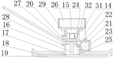
FIG. 2 is a side cross-sectional view of an intelligent pavement polisher of the present invention;
FIG. 3 is a schematic structural diagram of a connecting rod of the intelligent road surface polishing machine of the present invention;
FIG. 4 is a schematic diagram of an intelligent structure of the intelligent road surface polishing machine according to the present invention;
in the figure: l-sleeve, 2-storage battery box, 3-protective ring, 4-bearing I, 5-support rod, 6-rubber ring, 7-filter cylinder, 8-air hole, 9-rotating plate, 10-support rod, 11-grab handle, 12-switch, 13-screw hole, 14-connecting bolt, 15-motor, 16-main shaft, 17-connecting rod, 18-disc, 19-scraper, 20-rotating disc, 21-bracket, 22-bearing II, 23-fan blade, 24-roller, 25-sealing ring, 26-storage battery, 27-rotating shaft, 28-fixing pin, 29-electric switch, 30-Bluetooth bracelet, 31-Bluetooth adapter and 32-intelligent chip.
Detailed Description
In order to make the technical means, the creation characteristics, the achievement purposes and the effects of the invention easy to understand, the invention is further described with the specific embodiments.
Referring to fig. 1 to 4, the present invention provides a technical solution: an intelligent road surface polishing machine comprises a sleeve 1, a storage battery box 2 and a protection ring 3, wherein the protection ring 3 is arranged on the outer side of the sleeve 1, the storage battery box 2 is welded at the top of the sleeve 1, a bearing I4 is sleeved on the outer side of the sleeve 1, a support rod 5 is welded on the outer side of the bearing I4, a rubber ring 6 is bonded on the outer side of the protection ring 3, a filter cartridge 7 is installed on one side of the sleeve 1, an air hole 8 is formed in the outer wall of the sleeve 1, a rotating plate 9 is installed on one side of the sleeve 1, a support rod 10 is welded on one side of the rotating plate 9, a grab handle 11 is welded at the top end of the support rod 10, a switch 12 is installed on the grab handle 11 through a bolt, a screw hole 13 is formed in the storage battery box 2, a connecting bolt 14 is arranged on the inner side of the screw hole 13, a motor 15 is installed on the inner side of, the welding of the bottom of main shaft 16 has connecting rod 17, the outside side welding of connecting rod 17 has disc 18 and scraper blade 19, the welding of scraper blade 19 is in the bottom of disc 18, the welding has carousel 20 on the main shaft 16, the welding has support 21 on the inner wall of sleeve 1, the welding has two bearings 22 on the support 21, the inboard cover of two bearings 22 is equipped with flabellum 23, the gyro wheel 24 of one side bonding of flabellum 23, sealing washer 15 is installed through the bolt in the bottom of sleeve 1, the inboard card of battery box 2 has battery 26, rotor 9 installs the one side at sleeve 1 through pivot 27, rotor 9 is fixed on sleeve 1 through fixed pin 28, electric switch 29 is installed through the bolt in the bottom of battery box 2, bluetooth adapter 31 is installed through the bolt to battery box 2 opposite side, intelligent chip 32 is installed to the inboard of bluetooth adapter 31, the outside cover of grab handle 11 is equipped with bluetooth bracelet 30.
In a preferred embodiment of the present invention, the battery 26 is connected to the switch 12 through a wire, the switch 12 is connected to the bluetooth adapter 31 and the smart chip 32 through wires, the bluetooth adapter 31 is connected to the smart chip 32 through a wire, and the smart chip 32 is connected to the power switch 29 through a wire.
In a preferred embodiment of the present invention, the main shaft 16 is mounted on the output shaft of the motor 15 by bolts, and the sleeve 1 is clamped on the top of the disc 18 by a sealing ring 25.
In a preferred embodiment of the present invention, a tuyere is opened at one side of the sleeve 1, the filter cartridge 7 is installed at one side of the tuyere by bolts, and the bracket 21 is welded at the inner side of the tuyere.
In a preferred embodiment of the present invention, the roller 24 is a rubber roller, the roller 24 is clamped at the bottom of the turntable 20, and the roller 24 is matched with the turntable 20.
As a preferred embodiment of the present invention, the rotating plate 9 and the sleeve 1 are both provided with a pin hole, an inner wall of the pin hole is provided with a first internal thread, an outer wall of the fixing pin 28 is provided with a first external thread, and the first internal thread is matched with the first external thread.
In a preferred embodiment of the present invention, the number of the scrapers 19 is six, and the scrapers 19 are uniformly distributed on the bottom of the disc 18.
In a preferred embodiment of the present invention, the air holes 8 are uniformly distributed on the sleeve 1, and the air holes 8 are disposed outside the motor 15.
In a preferred embodiment of the present invention, the connection bolt 14 includes a torsion bar and a threaded sleeve, wherein the torsion bar is provided with a second external thread, the threaded sleeve is provided with a second internal thread inside, and the second external thread is matched with the second internal thread.
In a preferred embodiment of the present invention, one end of the supporting rod 5 is welded to the outer side of the bearing-bearing 4, the other end of the supporting rod 5 is welded to the inner side of the protection ring 3, and the supporting rods 5 are uniformly distributed on the inner side of the protection ring 3.
The working principle is as follows: the device provides required electric energy for all electric equipment of the device through the storage battery 26, the Bluetooth bracelet is unfastened from the grab handle and taken away from the wrist, the Bluetooth bracelet is connected with the intelligent chip through the Bluetooth adapter in a Bluetooth mode, the electric switch 29 is in a closed state, when the device is used and a certain distance exists in a work place, a road does not reach the passing standard, the connecting bolts 14 on the two devices are unscrewed from the screw holes 13, one of the two devices reversely falls on the top of the other device, the screw holes 13 on the storage battery boxes 2 on the two devices are aligned with each other, the two storage battery boxes 2 are fixed by the connecting bolts 14, the two support rods 10 are rotated by the fixing pins 28 in the same direction for 90 degrees, the rotating plate 9 is fixed with the sleeve 1 by the fixing pins 28, the two devices are transversely placed, and then the two devices are supported by the protective ring 3, the grab handle 11 is pulled, the protection ring 3 is rotated through the first bearing 4, and then the protection ring 3 can be conveyed by rolling, not only can the damage to the road caused by using a vehicle be effectively avoided, but also the physical power consumed by the carrying equipment can be effectively saved, the conveying is convenient, after the purpose is achieved, the connecting bolt is screwed off, the two devices are separated, the scraping plates 19 are placed on the ground, the grab handle 11 is held by a hand, the switch 12 is opened, the motor 15 drives the disc 18 and the scraping plates 19 to rotate through the spindle 16 and the connecting rod 17, the road surface is polished by the scraping plates 19, the spindle 16 drives the rotary table 20 to rotate, the rotary table 20 rotates the rolling wheels 24 through friction with the rolling wheels 24, and then the fan blades 23 are rotated to generate suction, dust generated during the polishing operation is sucked into the sleeve 1 through the gap between the scraping plates 19 at the bottom of the disc, by straining a effectual filtration of section of thick bamboo 7, and then avoid dust pollution environmental protection personnel healthy, simultaneously with external air through gas pocket 8 in inhaling sleeve 1, flow through straining a section of thick bamboo after 15 cooling to the motor, the effectual temperature that reduces the motor, guarantee the life of motor, in operation, in case personnel use grab handle 11 to take off the hand because of the hand is smooth or other reasons, and switch 12 can not in time be closed, lead to the rotation that equipment organism and grab handle 11 do not stop, say [ shutdown ] instruction through bluetooth bracelet 30, and then make bluetooth bracelet 30 pass through the bluetooth with this instruction transmission to intelligent chip 32 in, and then make intelligent chip 32 break off electric switch 29, and then make motor 15 close, thereby make grab handle 11 and equipment organism stall, avoid equipment out of control state, the safety of protective equipment and road surface.
While there have been shown and described what are at present considered the fundamental principles and essential features of the invention and its advantages, it will be apparent to those skilled in the art that the invention is not limited to the details of the foregoing exemplary embodiments, but is capable of other specific forms without departing from the spirit or essential characteristics thereof. The present embodiments are therefore to be considered in all respects as illustrative and not restrictive, the scope of the invention being indicated by the appended claims rather than by the foregoing description, and all changes which come within the meaning and range of equivalency of the claims are therefore intended to be embraced therein. Any reference sign in a claim should not be construed as limiting the claim concerned.
Furthermore, it should be understood that although the present description refers to embodiments, not every embodiment may contain only a single embodiment, and such description is for clarity only, and those skilled in the art should integrate the description, and the embodiments may be combined as appropriate to form other embodiments understood by those skilled in the art.
Claims (10)
1. The utility model provides an intelligence road surface burnishing machine which characterized in that: the storage battery box comprises a sleeve (1), a storage battery box (2) and a protection ring (3), wherein the protection ring (3) is arranged on the outer side of the sleeve (1), the storage battery box (2) is welded at the top of the sleeve (1), a first bearing (4) is sleeved on the outer side of the sleeve (1), a support rod (5) is welded on the outer side of the first bearing (4), a rubber ring (6) is bonded on the outer side of the protection ring (3), a filter cartridge (7) is installed on one side of the sleeve (1), an air hole (8) is formed in the outer wall of the sleeve (1), a rotating plate (9) is installed on one side of the sleeve (1), a support rod (10) is welded on one side of the rotating plate (9), a grab handle (11) is welded on the top end of the support rod (10), a switch (12) is installed on the grab handle (11) through a bolt, a screw hole (13) is formed in, the utility model discloses a battery box, including screw (13), motor (15), scraper blade (19), carousel (20), connecting rod (17), disc (18) and scraper blade (19) are welded to the outside side of connecting rod (17), the bottom of scraper blade (19) welding is in the bottom of disc (18), the welding has carousel (20) on spindle (16), the welding has support (21) on the inner wall of sleeve (1), the welding has bearing two (22) on support (21), the inboard cover of bearing two (22) is equipped with flabellum (23), the one side bonding of flabellum (23) has gyro wheel (24), sealing washer (15) are installed through the bolt in the bottom of sleeve (1), the inboard card of battery box (2) has battery (26), change board (9) and install the one side in sleeve (1) through pivot (27), change board (9) and fix on sleeve (1) through fixed pin (28), electric switch (29) are installed through the bolt in the bottom of battery box (2), bluetooth adapter (31) are installed through the bolt to battery box (2) opposite side, intelligent chip (32) are installed to the inboard of bluetooth adapter (31), the outside cover of grab handle (11) is equipped with bluetooth bracelet (30).
2. The intelligent road surface polisher of claim 1 with the following features: the storage battery (26) is connected with the switch (12) through an electric wire, the switch (12) is connected with the Bluetooth adapter (31) and the intelligent chip (32) through an electric wire, the Bluetooth adapter (31) is connected with the intelligent chip (32) through an electric wire, and the intelligent chip (32) is connected with the electric switch (29) through an electric wire.
3. The intelligent road surface polisher of claim 1 with the following features: the main shaft (16) is installed on an output shaft of the motor (15) through a bolt, and the sleeve (1) is clamped at the top of the disc (18) through a sealing ring (25).
4. The intelligent road surface polisher of claim 1 with the following features: an air opening is formed in one side of the sleeve (1), the filter cylinder (7) is installed on one side of the air opening through a bolt, and the support (21) is welded on the inner side of the air opening.
5. The intelligent road surface polisher of claim 1 with the following features: the roller (24) is a rubber roller, the roller (24) is clamped at the bottom of the turntable (20), and the roller (24) is matched with the turntable (20).
6. The intelligent road surface polisher of claim 1 with the following features: the rotating plate (9) and the sleeve (1) are provided with pin holes, the inner wall of each pin hole is provided with a first internal thread, the outer wall of the fixing pin (28) is provided with a first external thread, and the first internal thread is matched with the first external thread.
7. The intelligent road surface polisher of claim 1 with the following features: the number of the scrapers (19) is six, and the scrapers (19) are uniformly distributed at the bottom of the disc (18).
8. The intelligent road surface polisher of claim 1 with the following features: the air holes (8) are uniformly distributed on the sleeve (1), and the air holes (8) are formed in the outer side of the motor (15).
9. The intelligent road surface polisher of claim 1 with the following features: the connecting bolt (14) comprises a torsion bar and a threaded sleeve, wherein an external thread II is arranged on the torsion bar, an internal thread II is arranged on the inner side of the threaded sleeve, and the external thread II is matched with the internal thread II.
10. The intelligent road surface polisher of claim 1 with the following features: the one end welding of branch (5) is in the outside of bearing (4), the other end welding of branch (5) is in the inside of guard ring (3), branch (5) evenly distributed is in the inboard of guard ring (3).
Priority Applications (1)
| Application Number | Priority Date | Filing Date | Title |
|---|---|---|---|
| CN201911122920.XA CN110820484A (en) | 2019-11-16 | 2019-11-16 | Intelligence road surface burnishing machine |
Applications Claiming Priority (1)
| Application Number | Priority Date | Filing Date | Title |
|---|---|---|---|
| CN201911122920.XA CN110820484A (en) | 2019-11-16 | 2019-11-16 | Intelligence road surface burnishing machine |
Publications (1)
| Publication Number | Publication Date |
|---|---|
| CN110820484A true CN110820484A (en) | 2020-02-21 |
Family
ID=69555886
Family Applications (1)
| Application Number | Title | Priority Date | Filing Date |
|---|---|---|---|
| CN201911122920.XA Withdrawn CN110820484A (en) | 2019-11-16 | 2019-11-16 | Intelligence road surface burnishing machine |
Country Status (1)
| Country | Link |
|---|---|
| CN (1) | CN110820484A (en) |
Cited By (3)
| Publication number | Priority date | Publication date | Assignee | Title |
|---|---|---|---|---|
| WO2023102400A1 (en) * | 2021-12-01 | 2023-06-08 | Milwaukee Electric Tool Corporation | Anti-kickback control for battery pack powered trowels |
| US12462990B2 (en) | 2022-10-10 | 2025-11-04 | Milwaukee Electric Tool Corporation | Safety switch for a battery pack powered trowel |
| US12698636B2 (en) | 2022-05-11 | 2026-08-04 | Milwaukee Electric Tool Corporation | Battery pack powered trowel including blade pitch and speed control |
-
2019
- 2019-11-16 CN CN201911122920.XA patent/CN110820484A/en not_active Withdrawn
Cited By (3)
| Publication number | Priority date | Publication date | Assignee | Title |
|---|---|---|---|---|
| WO2023102400A1 (en) * | 2021-12-01 | 2023-06-08 | Milwaukee Electric Tool Corporation | Anti-kickback control for battery pack powered trowels |
| US12698636B2 (en) | 2022-05-11 | 2026-08-04 | Milwaukee Electric Tool Corporation | Battery pack powered trowel including blade pitch and speed control |
| US12462990B2 (en) | 2022-10-10 | 2025-11-04 | Milwaukee Electric Tool Corporation | Safety switch for a battery pack powered trowel |
Similar Documents
| Publication | Publication Date | Title |
|---|---|---|
| CN205852511U (en) | A kind of new automatic numerical control polishing for aluminium alloy wheel hub polishing | |
| CN209457970U (en) | A kind of coal mining atomizing de-dusting apparatus | |
| CN206500705U (en) | Beveler inside and outside a kind of general caliber | |
| CN211395547U (en) | Railway track sand removing device | |
| CN206748151U (en) | The belt sander that a kind of precision casting polishing uses | |
| CN206425940U (en) | A kind of efficient casting grinding device | |
| CN202763614U (en) | Grinding machine for bottom portion of spherical cylinder | |
| CN210714456U (en) | Mining and tunneling equipment | |
| CN109129101A (en) | A kind of burr processing unit of plastic products | |
| CN211239657U (en) | High-efficient linear electric motor of on-vehicle tent | |
| CN208528740U (en) | A kind of grinding apparatus of cloud carved lacquer ware | |
| CN210281773U (en) | Grinding device is used in processing of dabber | |
| CN207088223U (en) | A kind of saw blade type cutter structure and automatic plate cutting machine | |
| CN215617418U (en) | Shape following cooling mechanism of metallographic cutting machine | |
| CN221388047U (en) | Perlite processing is with high-efficient dust collector | |
| CN206475033U (en) | Jade angle lap machine | |
| CN112499101A (en) | Balance wheel driving mechanism of balance wheel sorting machine | |
| CN2033324U (en) | Dust-absorbing emery-wheel machine | |
| CN209424856U (en) | A kind of cone pulley forging that series is controllable detection prosthetic appliance | |
| CN219747589U (en) | Novel high-efficient shot-blasting machine | |
| CN219819169U (en) | A processing equipment for sheet metal components | |
| CN218136893U (en) | Edge grinding device for processing fireproof door | |
| CN108837944A (en) | A kind of iron remover | |
| CN222308313U (en) | Contact network grinding device | |
| CN223406608U (en) | A grinding device for a double-support crankshaft |
Legal Events
| Date | Code | Title | Description |
|---|---|---|---|
| PB01 | Publication | ||
| PB01 | Publication | ||
| SE01 | Entry into force of request for substantive examination | ||
| SE01 | Entry into force of request for substantive examination | ||
| WW01 | Invention patent application withdrawn after publication | ||
| WW01 | Invention patent application withdrawn after publication |
Application publication date: 20200221 |