CN110788569A - Crosshead guide sliding sleeve and machining method thereof - Google Patents
Crosshead guide sliding sleeve and machining method thereof Download PDFInfo
- Publication number
- CN110788569A CN110788569A CN201911022995.0A CN201911022995A CN110788569A CN 110788569 A CN110788569 A CN 110788569A CN 201911022995 A CN201911022995 A CN 201911022995A CN 110788569 A CN110788569 A CN 110788569A
- Authority
- CN
- China
- Prior art keywords
- sliding sleeve
- guide sliding
- crosshead guide
- cross
- crosshead
- Prior art date
- Legal status (The legal status is an assumption and is not a legal conclusion. Google has not performed a legal analysis and makes no representation as to the accuracy of the status listed.)
- Granted
Links
Images


Classifications
-
- B—PERFORMING OPERATIONS; TRANSPORTING
- B23—MACHINE TOOLS; METAL-WORKING NOT OTHERWISE PROVIDED FOR
- B23P—METAL-WORKING NOT OTHERWISE PROVIDED FOR; COMBINED OPERATIONS; UNIVERSAL MACHINE TOOLS
- B23P15/00—Making specific metal objects by operations not covered by a single other subclass or a group in this subclass
- B23P15/14—Making specific metal objects by operations not covered by a single other subclass or a group in this subclass gear parts, e.g. gear wheels
-
- F—MECHANICAL ENGINEERING; LIGHTING; HEATING; WEAPONS; BLASTING
- F04—POSITIVE - DISPLACEMENT MACHINES FOR LIQUIDS; PUMPS FOR LIQUIDS OR ELASTIC FLUIDS
- F04B—POSITIVE-DISPLACEMENT MACHINES FOR LIQUIDS; PUMPS
- F04B53/00—Component parts, details or accessories not provided for in, or of interest apart from, groups F04B1/00 - F04B23/00 or F04B39/00 - F04B47/00
Landscapes
- Engineering & Computer Science (AREA)
- Mechanical Engineering (AREA)
- General Engineering & Computer Science (AREA)
- Sliding-Contact Bearings (AREA)
- Details Of Reciprocating Pumps (AREA)
Abstract
本发明涉及柱塞泵技术领域,提供一种十字头导向滑套,包括导向滑套本体和外衬套,外衬套套设在导向滑套本体外,导向滑套的内圆和外圆均为圆弧结构,且其外圆的一端设有燕尾槽凹槽结构,其另外一端设有“L”型平凸台结构,具有工艺简单、安排合理、便于操作加工,同时提高了十字头导向滑套的加工精度和效率,可靠性高的优点。
The invention relates to the technical field of plunger pumps, and provides a cross-head guide sliding sleeve, which includes a guide sliding sleeve body and an outer bushing. Arc structure, and one end of the outer circle is provided with a dovetail groove groove structure, and the other end is provided with an "L" type flat boss structure, which has the advantages of simple process, reasonable arrangement, easy operation and processing, and at the same time, it improves the guiding sliding of the cross head. Set the advantages of machining accuracy and efficiency, and high reliability.
Description
技术领域technical field
本发明涉及柱塞泵技术领域,尤其涉及一种十字头导向滑套以及其加工方法。The invention relates to the technical field of plunger pumps, in particular to a cross-head guide sliding sleeve and a processing method thereof.
背景技术Background technique
柱塞泵是液压系统的一个重要装置,它依靠柱塞在缸体中往复运动,使密封工作容腔的容积发生变化来实现吸水、压水,柱塞泵具有额定压力高、结构紧凑、效率高和操作维修方便等优点。柱塞泵在各行各业有着广泛的应用,尤其在油气田开采领域占据着无可替代的关键作用,其中曲柄连杆机构作为柱塞泵的传动机构,通过将输入柱塞泵的旋转运动转化为柱塞的往复直线运动,将动能转化为压力能。十字头导向滑套作为动力端总成主要承载件,其外圆通过螺栓固定在动力端壳体上,内圆与十字头间隙配合,导向和支撑十字头在泵壳内的往复直线运动。为减少十字头与十字头导向滑套运动时磨损,带走摩擦热量,十字头导向滑套与十字头外圆装配时留有适当安装间隙,以便润滑油进入,冷却和润滑十字头和十字头导向滑套,带走摩擦热量。若安装间隙过大,则润滑油油压低,同时在运动时十字头与十字头导向滑套产生偏磨,加剧磨损;若安装间隙过小,则润滑油无法在十字头外圆和十字头导向滑套内圆之间形成油膜,此时十字头外圆因干摩擦快速升温、变形、扭曲,最终十字头导向滑套与十字头抱死,出现柱塞泵质量事故。因而十字头导向滑套的加工精度和装配精度是影响柱塞泵持续高效、平稳运转性能的决定性因素。The plunger pump is an important device in the hydraulic system. It relies on the reciprocating motion of the plunger in the cylinder body to change the volume of the sealed working cavity to achieve water absorption and water pressure. The plunger pump has high rated pressure, compact structure and high efficiency. High and convenient operation and maintenance. Plunger pumps are widely used in all walks of life, especially in the field of oil and gas field exploitation, which play an irreplaceable key role. The crank connecting rod mechanism, as the transmission mechanism of the plunger pump, converts the rotary motion of the input plunger pump into The reciprocating linear motion of the plunger converts kinetic energy into pressure energy. The crosshead guide sliding sleeve is the main bearing part of the power end assembly. Its outer circle is fixed on the power end housing by bolts, and the inner circle is clearance fit with the crosshead to guide and support the reciprocating linear motion of the crosshead in the pump housing. In order to reduce the wear and tear of the cross head and the cross head guide sliding sleeve during movement and take away the frictional heat, the cross head guide sliding sleeve and the cross head outer circle are assembled with a proper installation clearance, so that the lubricating oil can enter, cool and lubricate the cross head and the cross head. Guide sliding sleeve to take away frictional heat. If the installation clearance is too large, the oil pressure of the lubricating oil will be low, and at the same time, the crosshead and the guide sliding sleeve of the crosshead will produce eccentric wear during movement, which will aggravate the wear; An oil film is formed between the inner circle of the guide sliding sleeve. At this time, the outer circle of the cross head rapidly heats up, deforms and twists due to dry friction. Finally, the cross head guide sliding sleeve and the cross head are locked, resulting in a quality accident of the plunger pump. Therefore, the machining accuracy and assembly accuracy of the crosshead guide sliding sleeve are the decisive factors that affect the continuous efficient and smooth running performance of the plunger pump.
十字头导向滑套通常采用半圆筒形的合金铸铁材质,内外圆经精加工后其尺寸公差和形位公差要求十分苛刻,因而其机加工工艺直接影响着整泵的装配精度和实际使用效果。目前十字头导向滑套加工工艺普遍采用整体筒料粗加工外形----粗加工外圆----精加工外圆、燕尾槽----粗加工内圆----钻螺栓通孔和润滑油孔----锯床将导向滑套等分成4部分----上工装夹紧4片导向滑套,精加工内圆;这种加工工艺需用到工装夹具配合使用,操作繁琐、定心能力差,而且上、下单片十字头导向滑套内圆在工装上精加工,无法确保其内外圆同轴度和工装燕尾槽与实际泵壳燕尾槽完全一致,造成装配间隙不一样,精度差,影响导向滑套使用寿命和柱塞泵传动精度。The cross-head guide sliding sleeve is usually made of semi-cylindrical alloy cast iron. After finishing the inner and outer circles, the dimensional tolerance and geometric tolerance are very strict. Therefore, the machining process directly affects the assembly accuracy of the whole pump and the actual use effect. At present, the processing technology of the cross-head guide sliding sleeve generally adopts the rough machining shape of the overall cylinder material---rough machining the outer circle---finishing the outer circle and dovetail groove---roughing the inner circle---drilling the bolt through Holes and lubricating oil holes ---- the sawing machine divides the guide sleeve into 4 parts ---- the
发明内容SUMMARY OF THE INVENTION
(一)要解决的技术问题(1) Technical problems to be solved
本发明的目的是提供,用以解决现有的十字头导向滑套存在的结构复杂、制作工艺繁琐的缺点。The purpose of the present invention is to provide a solution for solving the disadvantages of complex structure and complicated manufacturing process of the existing cross-head guide sliding sleeve.
(二)发明内容(2) Content of the invention
为了解决上述技术问题,本发明提供一种十字头导向滑套,包括导向滑套本体和外衬套,外衬套套设在导向滑套本体外,导向滑套的内圆和外圆均为圆弧结构,且其外圆的一端设有燕尾槽凹槽结构,其另外一端设有“L”型平凸台结构。In order to solve the above technical problems, the present invention provides a cross-head guide sliding sleeve, which includes a guiding sliding sleeve body and an outer bushing, the outer bushing is sleeved outside the guiding sliding sleeve body, and the inner and outer circles of the guiding sliding sleeve are both circular Arc structure, and one end of the outer circle is provided with a dovetail groove groove structure, and the other end is provided with an "L"-shaped flat boss structure.
进一步的,“L”型平凸台结构上设置有螺栓定位通孔。Further, the "L"-shaped flat boss structure is provided with bolt positioning through holes.
进一步的,螺栓定位通孔设有八个,且所述八个螺栓定位通孔均匀的分布于所述“L”型平凸台结构。Further, eight bolt positioning through holes are provided, and the eight bolt positioning through holes are evenly distributed in the "L"-shaped flat boss structure.
进一步的,螺栓定位通孔旁还设有润滑油道孔。Further, a lubricating oil channel hole is also provided beside the bolt positioning through hole.
一种十字头导向滑套的加工方法,包括以下步骤:A processing method for a cross-head guide sliding sleeve, comprising the following steps:
1)毛坯下料:选取铸料筒料备用,人工筛选掉其中有气孔和夹渣的毛坯料;1) Blank blanking: select the casting cylinder material for use, and manually screen out the blanks with pores and slag inclusions;
2)粗加工:使用车床将步骤1)中的铸料筒料的端面至图纸所规定的长度,使用车床将步骤1)中的铸料筒料的加工出如权利要求1至5的“L”型平凸台结构,使用车床按照图纸的要求粗车出十字头导向滑套的内圆和外圆,并保留2mm的加工余量;2) Rough machining: use a lathe to make the end face of the casting cylinder material in step 1) to the length specified in the drawing, and use a lathe to process the casting cylinder material in step 1) into the "L" as claimed in
3)调质:将经过步骤1)至2)加工后的半成品进行调质处理,调质硬度HB190-220,调质处理完成后进行相应的检验;3) Quenching and tempering: the semi-finished products processed in steps 1) to 2) are quenched and tempered to a hardness of HB190-220, and the corresponding inspection is carried out after the quenching and tempering treatment is completed;
4)时效处理:将经过步骤1)至步骤3)处理后的半成品放置于储存室进行时效处理。4) Aging treatment: place the semi-finished product processed in steps 1) to 3) in a storage room for aging treatment.
5)半精加工:将经过步骤1)至步骤4)处理后的半成品放置于车床上,车床的三爪卡盘夹紧内圆,精加工十字头导向滑套的外圆至图纸要求的尺寸,精加工外圆上的燕尾槽至图纸要求的尺寸,精加工的十字头导向滑套的“L”型平凸台结构至图纸要求的尺寸;5) Semi-finishing: place the semi-finished product processed in steps 1) to 4) on the lathe, clamp the inner circle with the three-jaw chuck of the lathe, and finish machining the outer circle of the cross-head guide sliding sleeve to the size required by the drawing , Finish machining the dovetail groove on the outer circle to the size required by the drawing, and finish the "L" type flat boss structure of the cross head guide sliding sleeve to the size required by the drawing;
6)钻孔:按照图纸的要求加工出螺栓定位通孔和润滑油道孔;6) Drilling: According to the requirements of the drawings, the bolt positioning through holes and the lubricating oil passage holes are processed;
7)分型和去尖角毛刺:将经过步骤1)至6)处理后的十字头导向滑套等分为四个单片十字头导向滑套;7) Type and burr removal: Divide the cross-head guide sliding sleeve processed in steps 1) to 6) equally into four single-piece cross-head guide sliding sleeves;
8)连接固定:将步骤7)中的四个单片十字头导向滑套两个一组进行固定;8) Connection and fixation: fix the four single-piece cross-head guide sliding sleeves in step 7) in groups of two;
9)精加工:将十字头导向滑套固定在泵壳的相应位置,再使用镗床进行精加工;9) Finishing: fix the cross-head guide sliding sleeve at the corresponding position of the pump casing, and then use the boring machine for finishing;
10)清洗:使用气压枪多泵壳和十字头导向滑套的各个加工面进行吹洗;10) Cleaning: Use the multi-pump casing of the air pressure gun and each processing surface of the cross-head guide sliding sleeve to purge;
11)质检:检验、字头导向滑套在泵壳上的内圆尺寸、长度、表面粗糙度、形位公差,均达到图纸技术要求。11) Quality inspection: inspection, the inner circle size, length, surface roughness and shape and position tolerance of the prefix guide sliding sleeve on the pump casing all meet the technical requirements of the drawing.
一种十字头导向滑套的加工方法,在步骤2)中,使用卧式普通车床,使用其三爪卡盘夹紧十字头导向滑套的外圆一端,粗车十字头导向滑套端面至图纸要求长度尺寸,粗车外圆L型平凸台至外形尺寸要求。A processing method for a cross-head guide sliding sleeve. In step 2), a horizontal ordinary lathe is used, and its three-jaw chuck is used to clamp one end of the outer circle of the cross-head guide sliding sleeve, and the end face of the cross-head guide sliding sleeve is roughened to The drawings require the length and dimensions, and the outer circle L-shaped flat boss of the rough turning is up to the external dimension requirements.
进一步的,在步骤8)中,将两个单片十字头导向滑套安装在镗床精加工后的泵壳导向滑套支撑部位,用导向套螺栓进行固定,并穿铁丝串联,螺栓拧紧力矩为48N.m。Further, in step 8), two single-piece cross-head guide sliding sleeves are installed on the support part of the pump casing guide sliding sleeve after the boring machine finishing, fixed with guide sleeve bolts, and connected in series through iron wires, and the bolt tightening torque is: 48N.m.
(三)有益效果(3) Beneficial effects
本发明提供的一种十字头导向滑套,包括导向滑套本体和外衬套,外衬套套设在导向滑套本体外,导向滑套的内圆和外圆均为圆弧结构,且其外圆的一端设有燕尾槽凹槽结构,其另外一端设有“L”型平凸台结构,十字头导向滑套一端以燕尾槽进行定位,外圆贴死泵壳支撑连接板,另一端用两根特制高强度导向套螺栓进行固定,这样同时完成对十字头导向滑套的轴向和径向定位,安装定位牢靠,相比传统十字头导向滑套加工工艺设计精巧、工艺简单、安排合理、便于操作加工,同时提高了十字头导向滑套的加工精度和效率,可靠性高。A cross-head guide sliding sleeve provided by the present invention includes a guiding sliding sleeve body and an outer bushing, the outer bushing is sleeved outside the guiding sliding sleeve body, and the inner and outer circles of the guiding sliding sleeve are arc structures, and the One end of the outer circle is provided with a dovetail groove groove structure, and the other end is provided with an "L"-shaped flat boss structure. One end of the cross-head guide sliding sleeve is positioned with a dovetail groove. It is fixed with two special high-strength guide sleeve bolts, so that the axial and radial positioning of the cross-head guide sleeve can be completed at the same time, and the installation and positioning are firm. Compared with the traditional cross-head guide sleeve processing technology, the design is exquisite, the process is simple, and the arrangement Reasonable and easy to operate and process, meanwhile, the machining accuracy and efficiency of the cross-head guide sliding sleeve are improved, and the reliability is high.
同时提供了上述十字头导向滑套,能够快速高效的制作上述十字头导向滑套,提高了生产效率。At the same time, the above-mentioned cross-head guide sliding sleeve is provided, which can quickly and efficiently manufacture the above-mentioned cross-head guide sliding sleeve, thereby improving the production efficiency.
附图说明Description of drawings
为了更清楚地说明本发明实施例或现有技术中的技术方案,下面将对实施例或现有技术描述中所需要使用的附图做简单地介绍,显而易见地,下面描述中的附图是本发明的一些实施例,对于本领域普通技术人员来讲,在不付出创造性劳动的前提下,还可以根据这些附图获得其他的附图。In order to explain the embodiments of the present invention or the technical solutions in the prior art more clearly, the following briefly introduces the accompanying drawings that need to be used in the description of the embodiments or the prior art. Obviously, the accompanying drawings in the following description are For some embodiments of the present invention, for those of ordinary skill in the art, other drawings can also be obtained according to these drawings without creative efforts.
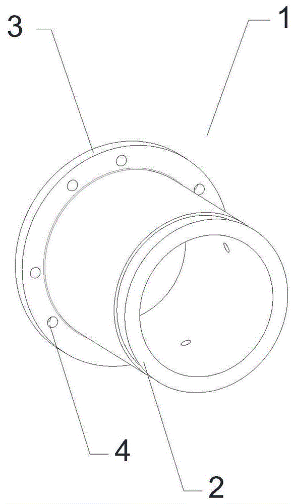
图1为本发明的一种十字头导向滑套的第一个视角的结构示意图。FIG. 1 is a schematic structural diagram of a cross-head guide sliding sleeve from a first perspective of the present invention.
图2为本发明的一种十字头导向滑套的第二个视角的结构示意图。FIG. 2 is a schematic structural diagram of a cross-head guide sliding sleeve from a second perspective of the present invention.
图3为本发明的一种十字头导向滑套的第三个视角的结构示意图。FIG. 3 is a schematic structural diagram of a cross-head guide sliding sleeve from a third angle of view of the present invention.
图4为本发明的一种十字头导向滑套与泵壳连接固定的示意图。FIG. 4 is a schematic diagram of the connection and fixation of a cross-head guide sliding sleeve and a pump casing according to the present invention.
图中附图标记说明:Description of the reference numbers in the figure:
1、导向滑套本体; 2、燕尾槽凹槽结构;1. Guide sliding sleeve body; 2. Dovetail groove groove structure;
3、”L”型平凸台结构; 4、螺栓连接通孔;3. "L" type flat boss structure; 4. Bolt connection through holes;
5、润滑油道孔; 6、泵壳。5. Lubricating oil passage hole; 6. Pump casing.
具体实施方式Detailed ways
为使本发明实施例的目的、技术方案和优点更加清楚,下面将结合本发明实施例中的附图,对本发明实施例中的技术方案进行清楚、完整地描述,显然,所描述的实施例是本发明一部分实施例,而不是全部的实施例。基于本发明中的实施例,本领域普通技术人员在没有做出创造性劳动前提下所获得的所有其他实施例,都属于本发明保护的范围。In order to make the purposes, technical solutions and advantages of the embodiments of the present invention clearer, the technical solutions in the embodiments of the present invention will be clearly and completely described below with reference to the accompanying drawings in the embodiments of the present invention. Obviously, the described embodiments These are some embodiments of the present invention, but not all embodiments. Based on the embodiments of the present invention, all other embodiments obtained by those of ordinary skill in the art without creative efforts shall fall within the protection scope of the present invention.
在本发明的描述中,需要说明的是,除非另有明确的规定和限定,术语“安装”、“相连”、“连接”应做广义理解,例如,可以是固定连接,也可以是可拆卸连接,或一体地连接;可以是机械连接,也可以是电连接;可以是直接相连,也可以通过中间媒介间接相连,可以是两个元件内部的连通。对于本领域的普通技术人员而言,可以具体情况理解上述术语在本发明中的具体含义。In the description of the present invention, it should be noted that the terms "installed", "connected" and "connected" should be understood in a broad sense, unless otherwise expressly specified and limited, for example, it may be a fixed connection or a detachable connection Connection, or integral connection; can be mechanical connection, can also be electrical connection; can be directly connected, can also be indirectly connected through an intermediate medium, can be internal communication between two elements. For those of ordinary skill in the art, the specific meanings of the above terms in the present invention can be understood in specific situations.
如图1、图2和图3所示,本发明的一种十字头导向滑套,包括导向滑套本体1和外衬套,外衬套套设在导向滑套本体1外,导向滑套的内圆和外圆均为圆弧结构,且其外圆的一端设有燕尾槽凹槽结构2,其另外一端设有”L”型平凸台结构3,”L”型平凸台结构3上设置有螺栓定位通孔,螺栓定位通孔设有八个,且所述八个螺栓定位通孔均匀的分布于所述”L”型平凸台结构3,螺栓定位通孔旁还设有润滑油道孔5。As shown in Figure 1, Figure 2 and Figure 3, a cross-head guide sliding sleeve of the present invention includes a guiding sliding
其加工方法如下:Its processing method is as follows:
1、毛坯下料:十字头导向滑套原材料为合金铸铁材质,毛坯为铸造筒料,毛坯不得有气孔、夹渣等铸造缺陷;1. Blank blanking: the raw material of the cross-head guide sliding sleeve is alloy cast iron, the blank is a casting cylinder, and the blank must not have casting defects such as pores and slag inclusions;
2、粗加工:在卧式普通车床上,三爪卡盘夹紧外圆一端,粗车十字头导向滑套端面至图纸要求长度尺寸,粗车外圆L型平凸台至外形尺寸要求,以同一基准粗车十字头导向滑套内外圆,留加工余量单边2mm;2. Rough machining: on a horizontal ordinary lathe, the three-jaw chuck clamps one end of the outer circle, the end face of the cross-head guide sliding sleeve for rough turning reaches the length and size required by the drawing, and the L-shaped flat boss on the outer circle for rough turning meets the requirements of the overall size. Rough turning the inner and outer circles of the sliding sleeve with the same reference, leaving a machining allowance of 2mm on one side;
3、调质:将粗加工后的半成品十字头导向滑套进行调质处理,调质硬度HB190-220,并检验其硬度是否达标;3. Quenching and tempering: the rough-processed semi-finished cross-head guide sliding sleeve is quenched and tempered, the hardness of which is HB190-220, and whether the hardness is up to the standard;
4、时效处理:将调质后的半成品放在自然环境下进行自然时效处理,从而消除工件的内应力,稳定组织;4. Aging treatment: put the quenched and tempered semi-finished products in the natural environment for natural aging treatment, so as to eliminate the internal stress of the workpiece and stabilize the structure;
5、半精加工:在车床上用三爪卡盘夹紧内圆,以内圆为基准,精车十字头导向滑套外圆至成品尺寸,精车外圆弧面上燕尾槽至图纸要求尺寸,精车L型平凸台平面至成品尺寸,表面粗糙度均达到Ra3.2;5. Semi-finishing: Clamp the inner circle with a three-jaw chuck on the lathe, with the inner circle as the benchmark, finish turning the cross-head guide sliding sleeve outer circle to the finished product size, and finish turning the dovetail groove on the outer arc surface to the size required by the drawing , The surface roughness of the L-shaped flat boss of the finishing machine is up to the finished product size, and the surface roughness reaches Ra3.2;
6、钻孔:按照图纸要求,在钻床上对十字头导向滑套L型平凸台上钻导向套螺栓连接通孔4,钻润滑油道孔5,攻顶丝螺纹孔和润滑油道接头连接螺纹孔;6. Drilling: According to the requirements of the drawings, on the drilling machine, drill the guide sleeve bolt connection through
7、锯开:将半精加工后的十字头导向滑套在锯床上夹紧,以中心轴线为基准,等分为4个单片十字头导向滑套;7. Sawing: Clamp the semi-finished cross-head guide sleeve on the sawing machine, and divide it into 4 single-piece cross-head guide sleeves equally based on the central axis;
8、去尖角毛刺:将单片十字头导向滑套打磨,去尖角毛刺;8. Remove sharp corner burrs: grind the single-piece cross head guide sliding sleeve to remove sharp corner burrs;
9、连接固定:取2个单片十字头导向滑套,安装在镗床精加工后的泵壳6导向滑套支撑部位,用导向套螺栓进行固定,并穿铁丝串联,螺栓拧紧力矩为48N.m;9. Connection and fixation: Take 2 single-piece cross-head guide sliding sleeves, install them on the support part of the pump casing 6 after the boring machine finishing, fix them with guide sleeve bolts, and connect them in series through iron wires. The tightening torque of the bolts is 48N. m;
10、精加工:在镗床上精加工固定在泵壳6相应位置的十字头导向滑套至成品尺寸,继续对泵壳6其余部位进行后续加工;10. Finishing: Finish the cross-head guide sliding sleeve fixed at the corresponding position of the pump casing 6 on the boring machine to the finished size, and continue to carry out subsequent processing on the rest of the pump casing 6;
11、清洗:用带压气枪对泵壳6及十字头导向滑套各加工面进行吹洗,去除表面铁削等异物;11. Cleaning: Use a pressurized air gun to purge the pump casing 6 and each processing surface of the cross-head guide sliding sleeve to remove foreign objects such as iron chips on the surface;
检验:按图检验十字头导向滑套在泵壳6上的内圆尺寸、长度、表面粗糙度、形位公差,均达到图纸技术要求,即可入库。Inspection: According to the drawing, inspect the inner circle size, length, surface roughness and shape and position tolerance of the cross-head guide sliding sleeve on the pump casing 6, all meet the technical requirements of the drawing, and it can be put into storage.
使用时,按照如图4所示的方法进行安装。具体来说,将步骤9中十字头导向滑套一端以燕尾槽进行定位,外圆贴死泵壳6支撑连接板,另一端用两根特制高强度导向套螺栓进行固定,这样同时完成对十字头导向滑套的轴向和径向定位,安装定位牢靠。When in use, install it as shown in Figure 4. Specifically, in step 9, one end of the guide sleeve of the cross head is positioned with a dovetail groove, the outer circle is attached to the pump casing 6 to support the connecting plate, and the other end is fixed with two special high-strength guide sleeve bolts. The axial and radial positioning of the head guide sliding sleeve ensures reliable installation and positioning.
本发明专利的优点如下:The advantages of the patent of the present invention are as follows:
1、本发明专利相比传统十字头导向滑套加工工艺设计精巧、工艺简单、安排合理、便于操作加工,同时提高了十字头导向滑套的加工精度和效率,可靠性高;1. Compared with the traditional cross-head guide sliding sleeve, the patent of the present invention has the advantages of exquisite design, simple process, reasonable arrangement, convenient operation and processing, and at the same time, the processing accuracy and efficiency of the cross-head guide sliding sleeve are improved, and the reliability is high;
2、本发明专利借助泵壳6安装固定对十字头导向滑套进行内圆精加工工艺,无需借助传统工装精加工,避免了工装上燕尾槽与实际泵壳6上燕尾槽不一致,提高了十字头导向滑套实际安装后内外圆同轴度和圆度。2. The patent of the present invention uses the pump casing 6 to install and fix the inner circle finishing process for the cross head guide sliding sleeve, without the need for traditional tooling finishing, which avoids the inconsistency between the dovetail groove on the tooling and the actual pump casing 6, and improves the cross The coaxiality and roundness of the inner and outer circles after the actual installation of the head guide sliding sleeve.
3、本发明专利十字头导向滑套单片精加工后无需从泵壳6上拆卸,避免了十字头导向滑套装配过程中的尺寸变形问题,同时确保十字头导向滑套与十字头之间的装配间隙,无需重复测量调整即可一次性完成装配工作,缩短了装配时间,提高了生产效率和装配精度。3. The patented crosshead guide sliding sleeve of the present invention does not need to be disassembled from the pump casing 6 after finishing the single piece, which avoids the problem of dimensional deformation during the assembly process of the crosshead guide sliding sleeve, and at the same time ensures the gap between the crosshead guide sliding sleeve and the crosshead. The assembly gap can be adjusted, and the assembly work can be completed at one time without repeated measurement and adjustment, which shortens the assembly time and improves the production efficiency and assembly accuracy.
以上所描述的装置实施例仅仅是示意性的,其中所述作为分离部件说明的单元可以是或者也可以不是物理上分开的,作为单元显示的部件可以是或者也可以不是物理单元,即可以位于一个地方,或者也可以分布到多个网络单元上。可以根据实际的需要选择其中的部分或者全部模块来实现本实施例方案的目的。本领域普通技术人员在不付出创造性的劳动的情况下,即可以理解并实施。The device embodiments described above are only illustrative, wherein the units described as separate components may or may not be physically separated, and the components shown as units may or may not be physical units, that is, they may be located in One place, or it can be distributed over multiple network elements. Some or all of the modules may be selected according to actual needs to achieve the purpose of the solution in this embodiment. Those of ordinary skill in the art can understand and implement it without creative effort.
最后应说明的是:以上实施例仅用以说明本发明的技术方案,而非对其限制;尽管参照前述实施例对本发明进行了详细的说明,本领域的普通技术人员应当理解:其依然可以对前述各实施例所记载的技术方案进行修改,或者对其中部分技术特征进行等同替换;而这些修改或者替换,并不使相应技术方案的本质脱离本发明各实施例技术方案的精神和范围。Finally, it should be noted that the above embodiments are only used to illustrate the technical solutions of the present invention, but not to limit them; although the present invention has been described in detail with reference to the foregoing embodiments, those of ordinary skill in the art should understand that it can still be The technical solutions described in the foregoing embodiments are modified, or some technical features thereof are equivalently replaced; and these modifications or replacements do not make the essence of the corresponding technical solutions deviate from the spirit and scope of the technical solutions of the embodiments of the present invention.
Claims (7)
Priority Applications (1)
| Application Number | Priority Date | Filing Date | Title |
|---|---|---|---|
| CN201911022995.0A CN110788569B (en) | 2019-10-25 | 2019-10-25 | Crosshead guide sliding sleeve and machining method thereof |
Applications Claiming Priority (1)
| Application Number | Priority Date | Filing Date | Title |
|---|---|---|---|
| CN201911022995.0A CN110788569B (en) | 2019-10-25 | 2019-10-25 | Crosshead guide sliding sleeve and machining method thereof |
Publications (2)
| Publication Number | Publication Date |
|---|---|
| CN110788569A true CN110788569A (en) | 2020-02-14 |
| CN110788569B CN110788569B (en) | 2021-05-07 |
Family
ID=69441249
Family Applications (1)
| Application Number | Title | Priority Date | Filing Date |
|---|---|---|---|
| CN201911022995.0A Active CN110788569B (en) | 2019-10-25 | 2019-10-25 | Crosshead guide sliding sleeve and machining method thereof |
Country Status (1)
| Country | Link |
|---|---|
| CN (1) | CN110788569B (en) |
Cited By (4)
| Publication number | Priority date | Publication date | Assignee | Title |
|---|---|---|---|---|
| CN111702422A (en) * | 2020-06-30 | 2020-09-25 | 重庆红江机械有限责任公司 | Machining method of crosshead sliding sleeve |
| CN111822952A (en) * | 2020-07-06 | 2020-10-27 | 姚琪 | Method for processing aluminum-based silicon carbide launching tube |
| CN112045372A (en) * | 2020-09-08 | 2020-12-08 | 重庆神箭汽车传动件有限责任公司 | Pump body machining method |
| CN112475785A (en) * | 2020-10-21 | 2021-03-12 | 湖北冶鑫汽车零部件有限公司 | Valve sleeve machining process |
Citations (6)
| Publication number | Priority date | Publication date | Assignee | Title |
|---|---|---|---|---|
| JP2002513116A (en) * | 1998-04-27 | 2002-05-08 | テーツェーゲー・ウニテック・アクチエンゲゼルシャフト | Axial piston variable machine |
| CN2746154Y (en) * | 2004-09-05 | 2005-12-14 | 范兴宽 | Lining engineering ceramic cylinder for mud pump |
| CN2900853Y (en) * | 2006-05-18 | 2007-05-16 | 四机赛瓦石油钻采设备有限公司 | Large displacement plunger pump |
| CN201372918Y (en) * | 2009-04-03 | 2009-12-30 | 中国石油集团渤海石油装备制造有限公司 | Plunger type water injection pump crosshead guide device |
| CN102328216A (en) * | 2011-09-01 | 2012-01-25 | 中国航空工业第六一八研究所 | Fixture for excircle finish turning and fixture processing method |
| CN102996665A (en) * | 2012-10-09 | 2013-03-27 | 天津天海同步科技股份有限公司 | Synchronizer sliding sleeve and machining method thereof |
-
2019
- 2019-10-25 CN CN201911022995.0A patent/CN110788569B/en active Active
Patent Citations (6)
| Publication number | Priority date | Publication date | Assignee | Title |
|---|---|---|---|---|
| JP2002513116A (en) * | 1998-04-27 | 2002-05-08 | テーツェーゲー・ウニテック・アクチエンゲゼルシャフト | Axial piston variable machine |
| CN2746154Y (en) * | 2004-09-05 | 2005-12-14 | 范兴宽 | Lining engineering ceramic cylinder for mud pump |
| CN2900853Y (en) * | 2006-05-18 | 2007-05-16 | 四机赛瓦石油钻采设备有限公司 | Large displacement plunger pump |
| CN201372918Y (en) * | 2009-04-03 | 2009-12-30 | 中国石油集团渤海石油装备制造有限公司 | Plunger type water injection pump crosshead guide device |
| CN102328216A (en) * | 2011-09-01 | 2012-01-25 | 中国航空工业第六一八研究所 | Fixture for excircle finish turning and fixture processing method |
| CN102996665A (en) * | 2012-10-09 | 2013-03-27 | 天津天海同步科技股份有限公司 | Synchronizer sliding sleeve and machining method thereof |
Cited By (5)
| Publication number | Priority date | Publication date | Assignee | Title |
|---|---|---|---|---|
| CN111702422A (en) * | 2020-06-30 | 2020-09-25 | 重庆红江机械有限责任公司 | Machining method of crosshead sliding sleeve |
| CN111822952A (en) * | 2020-07-06 | 2020-10-27 | 姚琪 | Method for processing aluminum-based silicon carbide launching tube |
| CN112045372A (en) * | 2020-09-08 | 2020-12-08 | 重庆神箭汽车传动件有限责任公司 | Pump body machining method |
| CN112045372B (en) * | 2020-09-08 | 2022-04-29 | 重庆神箭汽车传动件有限责任公司 | Pump body machining method |
| CN112475785A (en) * | 2020-10-21 | 2021-03-12 | 湖北冶鑫汽车零部件有限公司 | Valve sleeve machining process |
Also Published As
| Publication number | Publication date |
|---|---|
| CN110788569B (en) | 2021-05-07 |
Similar Documents
| Publication | Publication Date | Title |
|---|---|---|
| CN110788569B (en) | Crosshead guide sliding sleeve and machining method thereof | |
| CN103551856B (en) | Prevent the processing method that high precision large-sized titanium alloy thin wall foundry goods mounting edge is out of shape | |
| CN104723045A (en) | Machining process and tool for shaft with inner step hole with large depth-diameter ratio | |
| CN204449948U (en) | A kind of expanded hole fixture for automobile connecting bar processing | |
| CN110454380B (en) | Crosshead for plunger pump and processing and manufacturing method thereof | |
| CN111408751A (en) | Front-mounted full-stroke pneumatic chuck | |
| CN212857804U (en) | Full-stroke hollow pneumatic chuck | |
| CN204504279U (en) | A kind of Novel cylinder jacket right boring endoporus special fixture | |
| CN212384624U (en) | Front-mounted full-stroke pneumatic chuck | |
| CN201529780U (en) | Heavy caliber boring and rolling head | |
| CN115194201B (en) | Compact vibrator device for realizing low-frequency vibration auxiliary drilling | |
| CN204868389U (en) | Double -end hole grinding machine | |
| CN105729074B (en) | A kind of application method of full metal screw pump stator auxiliary machining device | |
| CN111251088A (en) | Supporting grinding device for crosshead pin and grinding method | |
| CN107511725B (en) | Precise movable center device | |
| CN115488403A (en) | A locomotive drive hollow shaft cross tooth processing device and method | |
| CN205393687U (en) | Collet chuck formula stick spool material is skinned and is processed guider | |
| CN108927687A (en) | A kind of milling machine mold being easily installed | |
| CN221967442U (en) | A fixture for machine tool processing | |
| CN208729264U (en) | A kind of milling machine mold being easily installed | |
| CN219336850U (en) | Quick fixture capable of realizing self-centering and multi-combination change | |
| CN111618594A (en) | High-efficiency precise multi-station circulating horizontal automatic machining center | |
| CN207414385U (en) | Internal cooling turning tool for supporting bearing bush boring | |
| CN207787715U (en) | Compressor main shaft truning fixture | |
| CN115519317A (en) | Machining deformation control method for large-scale copper casting thin-wall part |
Legal Events
| Date | Code | Title | Description |
|---|---|---|---|
| PB01 | Publication | ||
| PB01 | Publication | ||
| SE01 | Entry into force of request for substantive examination | ||
| SE01 | Entry into force of request for substantive examination | ||
| GR01 | Patent grant | ||
| GR01 | Patent grant | ||
| PE01 | Entry into force of the registration of the contract for pledge of patent right | ||
| PE01 | Entry into force of the registration of the contract for pledge of patent right |
Denomination of invention: A crosshead guide slide sleeve and its processing method Granted publication date: 20210507 Pledgee: Hubei Bank Co.,Ltd. Jingzhou Jingzhou District Branch Pledgor: HUBEI PETROKH MACHINE MANUFACTURING Co.,Ltd. Registration number: Y2025980016474 |