CN110729153A - Elastic piece reset anti-rotation relay - Google Patents
Elastic piece reset anti-rotation relay Download PDFInfo
- Publication number
- CN110729153A CN110729153A CN201911039250.5A CN201911039250A CN110729153A CN 110729153 A CN110729153 A CN 110729153A CN 201911039250 A CN201911039250 A CN 201911039250A CN 110729153 A CN110729153 A CN 110729153A
- Authority
- CN
- China
- Prior art keywords
- arm
- insulating
- point block
- moving point
- shell
- Prior art date
- Legal status (The legal status is an assumption and is not a legal conclusion. Google has not performed a legal analysis and makes no representation as to the accuracy of the status listed.)
- Pending
Links
Images



Classifications
-
- H—ELECTRICITY
- H01—ELECTRIC ELEMENTS
- H01H—ELECTRIC SWITCHES; RELAYS; SELECTORS; EMERGENCY PROTECTIVE DEVICES
- H01H50/00—Details of electromagnetic relays
- H01H50/02—Bases; Casings; Covers
-
- H—ELECTRICITY
- H01—ELECTRIC ELEMENTS
- H01H—ELECTRIC SWITCHES; RELAYS; SELECTORS; EMERGENCY PROTECTIVE DEVICES
- H01H3/00—Mechanisms for operating contacts
- H01H3/32—Driving mechanisms, i.e. for transmitting driving force to the contacts
- H01H3/38—Driving mechanisms, i.e. for transmitting driving force to the contacts using spring or other flexible shaft coupling
-
- H—ELECTRICITY
- H01—ELECTRIC ELEMENTS
- H01H—ELECTRIC SWITCHES; RELAYS; SELECTORS; EMERGENCY PROTECTIVE DEVICES
- H01H50/00—Details of electromagnetic relays
- H01H50/64—Driving arrangements between movable part of magnetic circuit and contact
Landscapes
- Physics & Mathematics (AREA)
- Electromagnetism (AREA)
- Electromagnets (AREA)
Abstract
本发明涉及继电器技术领域,尤其公开了一种弹片复位防转动式继电器,包括绝缘壳、设置于绝缘壳的电磁铁及两个静端子、与电磁铁活动配合的推杆组件、推杆组件设有动点块;推杆组件还包括杆体、衔铁及第一弹片,第一弹片呈V型,第一弹片具有交叉设置的第一臂部及第二臂部,第一臂部、第二臂部均设置于绝缘壳;利用第一弹片替换现有技术中用于驱动推杆组件复位的弹簧,第一弹片能够在很小的空间距离内为动点块提供合适的复位弹力,降低推杆组件的高度,进而降低整个继电器的高度,使得继电器符合小型化的规格要求。第一弹片设置于绝缘壳,防止杆体连带动点块转动所引起的导通不良,确保继电器使用性能的稳定性。
The invention relates to the technical field of relays, and in particular discloses a shrapnel reset and anti-rotation relay, comprising an insulating shell, an electromagnet and two static terminals arranged on the insulating shell, a push rod assembly movably cooperating with the electromagnet, and a push rod assembly device. There is a moving point block; the push rod assembly also includes a rod body, an armature and a first shrapnel, the first shrapnel is V-shaped, and the first shrapnel has a first arm portion and a second arm portion arranged in a cross, the first arm portion and the second arm portion. The first shrapnel is used to replace the spring used to drive the push rod assembly to reset in the prior art, and the first shrapnel can provide a suitable reset elastic force for the moving point block within a small space distance, reducing the push rod The height of the components, thereby reducing the height of the entire relay, makes the relay meet the miniaturization specification requirements. The first shrapnel is arranged on the insulating shell to prevent poor conduction caused by the rotation of the point block in conjunction with the rod body, and to ensure the stability of the relay's performance.
Description
技术领域technical field
本发明涉及继电器技术领域,尤其公开了一种弹片复位防转动式继电器。The invention relates to the technical field of relays, and particularly discloses a shrapnel reset and anti-rotation relay.
背景技术Background technique
继电器是各种电路控制中常用的自动开关,继电器的构造多种多样,现有技术中继电器常常配置有活动的推杆单元及推动推杆单元复位的弹簧,由于弹簧自身存在的缺陷,使得弹簧不能再很小的空间距离内为推杆单元提供复位弹力,如此,就需要为弹簧配置较大的空间距离,这就造成了推杆单元高度的增加,也带来了整个继电器高度的增加,致使继电器不能满足小型化的规格要求。此外,由于弹簧对推杆单元没有限位作用,推杆单元往往会因为发生转动而无法实现正常的导通,导致继电器使用不良。Relays are automatic switches commonly used in various circuit controls. The structures of relays are various. In the prior art, relays are often equipped with a movable push rod unit and a spring that pushes the push rod unit to reset. Due to the defects of the spring itself, the spring It is no longer possible to provide the reset elastic force for the push rod unit in a small space distance. In this way, it is necessary to configure a larger space distance for the spring, which causes the increase of the height of the push rod unit and the height of the entire relay. As a result, the relay cannot meet the miniaturized specification requirements. In addition, since the spring has no limiting effect on the push rod unit, the push rod unit often cannot achieve normal conduction due to rotation, resulting in poor use of the relay.
发明内容SUMMARY OF THE INVENTION
为了克服现有技术中存在的缺点和不足,本发明的目的在于提供一种弹片复位防转动式继电器,利用第一弹片替换现有技术中用于驱动推杆组件复位的弹簧,第一弹片能够在很小的空间距离内为动点块提供合适的复位弹力,使得继电器符合小型化的规格要求;第一弹片防止杆体连带动点块转动所引起的导通不良,确保继电器使用性能的稳定性。In order to overcome the shortcomings and deficiencies existing in the prior art, the purpose of the present invention is to provide an anti-rotation relay for shrapnel reset. Provide appropriate reset elastic force for the moving point block within a small space distance, so that the relay meets the miniaturization specification requirements; the first shrapnel prevents poor conduction caused by the rotation of the moving point block with the rod body, and ensures the stability of the relay performance. .
为实现上述目的,本发明的一种弹片复位防转动式继电器,包括绝缘壳、设置于绝缘壳的电磁铁及两个静端子、与电磁铁活动配合的推杆组件、推杆组件设有动点块,电磁铁用于驱动推杆组件移动,动点块用于导通两个静端子;推杆组件还包括杆体、衔铁及第一弹片,衔铁、动点块、第一弹片均设置于杆体,第一弹片具有交叉设置的第一臂部及第二臂部,第一臂部、第二臂部均设置于绝缘壳。In order to achieve the above purpose, a shrapnel reset anti-rotation relay of the present invention includes an insulating shell, an electromagnet and two static terminals arranged on the insulating shell, a push rod assembly movably cooperated with the electromagnet, and the push rod assembly is provided with a moving rod. The point block, the electromagnet is used to drive the push rod assembly to move, and the moving point block is used to conduct the two static terminals; the push rod assembly also includes a rod body, an armature and a first shrapnel, and the armature, the moving point block and the first shrapnel are all arranged in In the rod body, the first elastic piece has a first arm portion and a second arm portion which are arranged crosswise, and the first arm portion and the second arm portion are both arranged in the insulating shell.
较佳地,所述第一弹片为一体式构造,第一弹片还包括基片,第一臂部、第二臂部分别设置于基片的两端,基片设置于杆体,动点块位于基片与衔铁之间,臂部朝远离基片的方向并朝远离动点块的方向延伸设置,第一臂部、第二臂部靠近基片一端之间的距离小于第一臂部、第二臂部远离基片一端之间的距离,臂部远离基片的一端设置于绝缘壳。Preferably, the first elastic piece is of one-piece structure, the first elastic piece further includes a base piece, the first arm part and the second arm part are respectively arranged on both ends of the base piece, the base piece is arranged on the rod body, and the moving point block is located in the base piece. Between the substrate and the armature, the arm portion is extended in the direction away from the substrate and away from the moving point block, and the distance between the first arm portion and the second arm portion close to one end of the substrate is smaller than that of the first arm portion and the second arm portion. The distance between one end of the two arm parts away from the substrate, and the end of the arm part away from the substrate is arranged in the insulating shell.
较佳地,所述推杆组件还包括第二弹片,动点块滑动设置于杆体,第二弹片包括交叉设置的第三臂部、第四臂部,第三臂部、第四臂部分别作用于杆体及动点块,第二弹片用于驱动动点块复位,第一弹片、第二弹片分别位于动点块的两侧。Preferably, the push rod assembly further includes a second elastic piece, the moving point block is slidably arranged on the rod body, and the second elastic piece includes a third arm portion and a fourth arm portion that are arranged crosswise, and the third arm portion and the fourth arm portion are respectively Acting on the rod body and the moving point block, the second elastic sheet is used to drive the moving point block to reset, and the first elastic sheet and the second elastic sheet are respectively located on both sides of the moving point block.
较佳地,所述杆体设有位于衔铁与动点块之间的挡止部,第三臂部的自由端、第四臂部的自由端均设有穿孔,杆体容设在穿孔内,动点块、挡止部彼此靠近的一侧分别挡止抵触第三臂部、第四臂部。Preferably, the rod body is provided with a stop portion located between the armature and the moving point block, the free end of the third arm portion and the free end of the fourth arm portion are provided with perforations, and the rod body is accommodated in the perforations, and the movable The side of the point block and the blocking portion which are close to each other respectively blocks and interferes with the third arm portion and the fourth arm portion.
较佳地,所述推杆组件包括滑动设置于杆体外侧的绝缘体,动点块设置于绝缘体,绝缘体设有两个第一卡肋,第三臂部的自由端或第四臂部的自由端卡持在两个第一卡肋之间。Preferably, the push rod assembly includes an insulator slidably disposed on the outside of the rod body, the moving point block is disposed on the insulator, the insulator is provided with two first clamping ribs, the free end of the third arm portion or the free end of the fourth arm portion. It is clamped between the two first clamping ribs.
较佳地,所述绝缘壳设有多个第二卡肋,第一臂部的自由端、第二臂部的自由端夹持在相邻的两个第二卡肋之间。Preferably, the insulating case is provided with a plurality of second locking ribs, and the free end of the first arm portion and the free end of the second arm portion are clamped between two adjacent second locking ribs.
较佳地,所述电磁铁包括轭铁壳、设置于轭铁壳内的绝缘骨架及铁芯、绕设于绝缘骨架外侧的电磁线圈、位于绝缘骨架内的磁铁圈,绝缘壳设置于轭铁壳,绝缘骨架设有贯穿绝缘骨架的通孔,铁芯位于通孔的一端内,杆体与铁芯滑动设置,衔铁滑动容设在通孔内,磁铁圈位于通孔内,磁铁圈、电磁线圈均环绕衔铁设置,磁铁圈的磁场方向与电磁线圈通电后产生的磁场方向同向或反向。Preferably, the electromagnet includes a yoke shell, an insulating skeleton and an iron core arranged in the yoke shell, an electromagnetic coil wound on the outside of the insulating skeleton, and a magnet coil located in the insulating skeleton, and the insulating shell is arranged on the yoke. The shell, the insulating frame is provided with a through hole passing through the insulating frame, the iron core is located in one end of the through hole, the rod body and the iron core are slidably arranged, the armature is slidably accommodated in the through hole, the magnet coil is located in the through hole, the magnet coil and the electromagnetic coil are located in the through hole. All are arranged around the armature, and the direction of the magnetic field of the magnet coil is the same or opposite to the direction of the magnetic field generated after the electromagnetic coil is energized.
较佳地,所述轭铁壳包括轭铁板及与轭铁板连接的轭铁件,绝缘骨架、绝缘壳分别位于轭铁板的两侧,铁芯设置于轭铁板,轭铁板设有伸入通孔内的轭铁筒,衔铁、铁芯均位于轭铁筒内,磁铁圈套设在轭铁筒外侧。Preferably, the yoke iron shell includes a yoke iron plate and a yoke iron piece connected to the yoke iron plate, the insulating frame and the insulating shell are respectively located on both sides of the yoke iron plate, the iron core is arranged on the yoke iron plate, and the yoke iron plate is arranged on the yoke iron plate. There is a yoke iron barrel extending into the through hole, the armature and the iron core are all located in the yoke iron barrel, and the magnet ring is sleeved on the outside of the yoke iron barrel.
较佳地,所述绝缘骨架设有突伸入通孔内的挡止圈,轭铁件设有突伸入通孔的另一端内的定位筒,磁铁圈夹持在挡止圈与定位筒之间。Preferably, the insulating frame is provided with a stop ring protruding into the through hole, the yoke is provided with a positioning cylinder protruding into the other end of the through hole, and the magnet ring is clamped between the stop ring and the positioning cylinder. between.
较佳地,还包括包覆在绝缘壳及电磁铁外侧的绝缘罩,静端子的一端显露出绝缘罩,绝缘骨架设有贯穿轭铁壳的突出部,突出部设有与电磁线圈导通并显露出绝缘罩的供电端子,绝缘壳设有容置盲槽,轭铁壳遮盖容置盲槽的开口,第一弹片、动点块、第二弹片、静端子的另一端均位于容置盲槽。Preferably, it also includes an insulating cover covering the insulating shell and the outside of the electromagnet, the insulating cover is exposed at one end of the static terminal, the insulating skeleton is provided with a protruding part that penetrates the yoke shell, and the protruding part is provided with a conductive and parallel connection with the electromagnetic coil. The power supply terminal of the insulating cover is exposed. The insulating shell is provided with a blind slot for accommodating it. The yoke iron shell covers the opening of the blind slot. groove.
本发明的有益效果:利用第一弹片替换现有技术中用于驱动推杆组件复位的弹簧,第一弹片能够在很小的空间距离内为动点块提供合适的复位弹力,降低推杆组件的高度,进而降低整个继电器的高度,使得继电器符合小型化的规格要求。第一弹片设置于绝缘壳,防止杆体连带动点块转动所引起的导通不良,确保继电器使用性能的稳定性。The beneficial effects of the present invention are as follows: the first elastic piece is used to replace the spring used to drive the push rod assembly to reset in the prior art. The height of the relay reduces the height of the entire relay, so that the relay meets the miniaturization specification requirements. The first shrapnel is arranged on the insulating shell to prevent poor conduction caused by the rotation of the point block in conjunction with the rod body, and to ensure the stability of the relay's performance.
附图说明Description of drawings
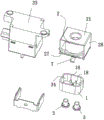
图1为本发明的立体结构示意图;Fig. 1 is the three-dimensional structure schematic diagram of the present invention;
图2为本发明的分解结构示意图;Fig. 2 is the exploded structure schematic diagram of the present invention;
图3为本发明的推杆组件的立体结构示意图;3 is a schematic three-dimensional structure diagram of the push rod assembly of the present invention;
图4为本发明的推杆组件的分解结构示意图;Fig. 4 is the exploded structure schematic diagram of the push rod assembly of the present invention;
图5为本发明的电磁铁与推杆组件的分解结构示意图;5 is a schematic diagram of an exploded structure of an electromagnet and a push rod assembly of the present invention;
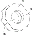
图6为本发明的绝缘骨架的立体结构示意图。FIG. 6 is a schematic three-dimensional structure diagram of the insulating skeleton of the present invention.
附图标记包括:Reference numerals include:
1—绝缘壳 2—电磁铁 3—静端子1—
4—动点块 5—杆体 6—衔铁4—moving
7—第一弹片 8—第一臂部 9—第二臂部7—First shrapnel 8—
11—基片 12—第二弹片 13—第三臂部11—
14—第四臂部 15—挡止部 16—绝缘体14—
17—第一卡肋 18—第二卡肋 19—第三卡肋17—The
21—轭铁壳 22—绝缘骨架 23—铁芯21—
24—电磁线圈 25—磁铁圈 26—通孔24—
27—轭铁板 28—轭铁件 29—轭铁筒27—yoke iron
31—挡止圈 32—定位筒 33—绝缘罩31—
34—容置盲槽。34—Accommodating blind slots.
具体实施方式Detailed ways
为了便于本领域技术人员的理解,下面结合实施例及附图对本发明作进一步的说明,实施方式提及的内容并非对本发明的限定。In order to facilitate the understanding of those skilled in the art, the present invention will be further described below with reference to the embodiments and the accompanying drawings, and the contents mentioned in the embodiments are not intended to limit the present invention.
请参阅图1至图6所示,本发明的一种弹片复位防转动式继电器,包括绝缘壳1、安装设置在绝缘壳1上的电磁铁2及两个静端子3、与电磁铁2活动配合的推杆组件、推杆组件设有动点块4,电磁铁2用于驱动推杆组件移动,动点块4用于导通两个静端子3,动点块4采用导电金属制成,动点块4大致为矩形平板。Please refer to FIG. 1 to FIG. 6 , a shrapnel reset anti-rotation relay of the present invention includes an insulating shell 1 , an
推杆组件还包括杆体5、衔铁6及第一弹片7,杆体5大致为直条状圆柱,衔铁6、动点块4、第一弹片7均安装设置在杆体5上,衔铁6、第一弹片7分别安装在杆体5的左右两端,动点块4位于衔铁6与第一弹片7之间,第一弹片7大致呈V型,第一弹片7具有交叉设置的第一臂部8及第二臂部9,第一臂部8、第二臂部9大致为矩形平板,第一臂部8的自由端、第二臂部9的自由端均设置在绝缘壳1上。The push rod assembly also includes a
利用第一弹片7替换现有技术中用于驱动推杆组件复位的弹簧,第一弹片7能够在很小的空间距离内为动点块4提供合适的复位弹力,降低推杆组件的高度,进而降低整个继电器的高度,使得继电器符合小型化的规格要求。第一弹片7的臂部安装设置在绝缘壳1上,利用绝缘壳1限位住第一弹片7,防止杆体5连带动点块4转动所引起的导通不良,确保继电器使用性能的稳定性。The first
所述第一弹片7为一体式构造,第一弹片7采用金属材料冲切、弯折而成,第一弹片7还包括基片11,第一臂部8、第二臂部9分别设置在基片11的左右两端,基片11安装固定在杆体5上,动点块4位于基片11与衔铁6之间,臂部朝远离基片11的方向并朝远离动点块4的方向延伸设置,第一臂部8、第二臂部9靠近基片11一端之间的距离小于第一臂部8、第二臂部9远离基片11一端之间的距离,臂部远离基片11的一端设置在绝缘壳1上。The first
电磁铁2得电后产生磁性力,磁性力吸引衔铁6使得衔铁6带动杆体5移动,移动的杆体5连带动点块4一起移动,从而使得动点块4导通两个静端子3。在杆体5移动的过程中,杆体5挤压第一弹片7使得第一弹片7发生弹性形变而具有弹性势能,当电磁铁2失电后,电磁铁2失去磁性力,第一弹片7在自身弹性回复力作用下驱动推杆组件恢复原位。After the
所述推杆组件还包括第二弹片12,动点块4滑动设置在杆体5上,杆体5贯穿动点块4,第二弹片12大致呈V型,第二弹片12包括交叉设置的第三臂部13、第四臂部14,第三臂部13、第四臂部14分别作用在杆体5上及动点块4上,第二弹片12用于驱动动点块4复位,第一弹片7、第二弹片12分别位于动点块4的左右两侧。第二弹片12同样为一体式构造,第二弹片12采用金属材料冲切、弯折而成,第三臂部13的一端与第四臂部14的一端直接连接。The push rod assembly further includes a second
当电磁铁2的磁性力驱动衔铁6使得动点块4导通两个静端子3时,使得动点块4相对杆体5滑动,相对杆体5滑动的动点块4挤压第二弹片12使得第二弹片12发生弹性变形而具有弹性势能,第二弹片12的弹性回复力驱动动点块4稳固压持抵触在静端子3上,避免继电器受到震动而导致动点块4与静端子3分离。当电磁铁2的磁性力消失后,第二弹片12在弹性力作用下驱动动点块4恢复原位。When the magnetic force of the
利用第二弹片12替换现有技术中用于驱动动点块4复位的弹簧,相较于现有技术中驱动动点块4复位的弹簧,第二弹片12能够在很小的空间距离内为动点块4提供合适的复位弹力,进一步降低推杆组件的高度,从而辅助降低整个继电器的高度,使得继电器符合小型化的规格要求。The second
所述杆体5上设置有位于衔铁6与动点块4之间的挡止部15,挡止部15环绕杆体5的中心轴线设置,第三臂部13的自由端、第四臂部14的自由端均设有穿孔,穿孔贯穿第三臂部13、第四臂部14,杆体5容设在穿孔内,动点块4、挡止部15彼此靠近的一侧分别挡止抵触在第三臂部13上、第四臂部14上。The
在第二弹片12与杆体5的装配过程中,无需第三臂部13与杆体5固定连接,同时也无需第四臂部14与杆体5(或动点块4)固定连接,大大提升第二弹片12与杆体5之间的拆装效率。During the assembly process of the second
所述推杆组件包括滑动设置在杆体5外侧的绝缘体16,绝缘体16采用绝缘塑料制成,动点块4安装设置在绝缘体16上,优选地,动点块4与绝缘体16镶埋成型在一起,确保绝缘体16与动点块4稳固连接在一起,避免动点块4与绝缘体16之间发生相对移动而影响继电器的使用性能。绝缘体16上设置有两个第一卡肋17,两个第一卡肋17彼此间隔且平行设置,第三臂部13的自由端或第四臂部14的自由端卡持在两个第一卡肋17之间。利用两个第一卡肋17挡止限位第三臂部13或第四臂部14,进而防止第二弹片12相对杆体5转动。The push rod assembly includes an
所述绝缘壳1上设置有多个第二卡肋18,第一臂部8的自由端、第二臂部9的自由端夹持在相邻的两个第二卡肋18之间。本实施例中,第二卡肋18的数量为四个,第一臂部8的自由端夹持在两个第二卡肋18之间,第二臂部9的自由端夹持在另外两个第二卡肋18之间。利用相邻的两个第二卡肋18挡止限位第一臂部8及第二臂部9,防止第一弹片7相对绝缘壳1转动,从而防止杆体5相对绝缘壳1转动。The insulating shell 1 is provided with a plurality of
绝缘体16设有两个第三卡肋19,第一卡肋17、第三卡肋19分别位于绝缘体16彼此远离的两侧上,基片11夹持在两个第三卡肋19之间,利用两个第三卡肋19挡止限位基片11,从而保证绝缘体16不会相对杆体5转动。The
所述电磁铁2包括轭铁壳21、安装设置在轭铁壳21内的绝缘骨架22及铁芯23、绕设在绝缘骨架22外侧的电磁线圈24、位于绝缘骨架22内的磁铁圈25,绝缘壳1设置在轭铁壳21的外侧,绝缘骨架22设置有贯穿绝缘骨架22的通孔26,铁芯23位于通孔26的一端内,杆体5与铁芯23滑动设置,杆体5远离第一弹片7的一端贯穿铁芯23,衔铁6、挡止部15分别位于铁芯23的左右两侧,衔铁6滑动容设在通孔26内,磁铁圈25位于通孔26内,磁铁圈25采用永磁铁制成,磁铁圈25大致呈圆环形,磁铁圈25、电磁线圈24均环绕衔铁6设置,磁铁圈25的磁场方向与电磁线圈24通电后产生的磁场方向同向或反向。The
在继电器的使用过程中,向电磁线圈24通正向电流,磁铁圈25的磁场与电磁线圈24通电后产生的磁场叠加,提高线圈吸合能力,使得铁芯23具有大的磁性力驱动衔铁6移动,相较于单独使用电磁线圈24,降低电磁线圈24的功率,避免电磁线圈24因大功率发热而烧坏;小功率的电磁线圈24缩小线圈的体积,使得电磁铁2的体积缩小,进而缩小整个继电器的体积,使得继电器符合小型化的规格需求。向电磁线圈24通反向电流,磁铁圈25的磁场与电磁线圈24通电后产生的磁场抵消,第一弹片7即可轻松驱动推杆组件复位,避免磁铁圈25的磁性干扰推杆组件的正常复位。During the use of the relay, a forward current is passed to the
所述轭铁壳21包括轭铁板27及与轭铁板27连接的轭铁件28,轭铁板27大致为矩形平板,轭铁件28呈U型,绝缘骨架22、绝缘壳1分别位于轭铁板27的左右两侧,铁芯23安装设置在轭铁板27上,轭铁板27设有伸入通孔26内的轭铁筒29,轭铁筒29大致为中空的圆柱,衔铁6、铁芯23均位于轭铁筒29内,磁铁圈25套设在轭铁筒29外侧。利用轭铁筒29对磁铁圈25的位置进行限位,防止磁铁圈25沿通孔26的径向方向移动而导致使用不良。The
所述绝缘骨架22设有突伸入通孔26内的挡止圈31,挡止圈31自通孔26的内孔壁突设而成,轭铁件28安装有突伸入通孔26的另一端内的定位筒32,定位筒32大致呈中空圆柱状,定位筒32套设在轭铁筒29的外侧,磁铁圈25夹持在挡止圈31与定位筒32之间。利用定位筒32与挡止圈31的配合,避免磁铁圈25沿通孔26的轴向方向移动,避免磁铁圈25发生位置变化而导致使用不良。The insulating
还包括包覆在绝缘壳1及电磁铁2外侧的绝缘罩33,绝缘罩33采用绝缘塑料制成,静端子3的一端显露出绝缘罩33,绝缘骨架22上设置有贯穿轭铁壳21的突出部,突出部上安装有与电磁线圈24导通并显露出绝缘罩33的供电端子,外界的电源经由供电端子对电磁线圈24供电。It also includes an insulating
绝缘壳1采用陶瓷材料制成,绝缘壳1上设置有容置盲槽34,轭铁壳21用于遮盖住容置盲槽34的开口,第一弹片7、动点块4、第二弹片12、静端子3的另一端均位于容置盲槽34,利用绝缘壳1防护第一弹片7、动点块4、第二弹片12、静端子3,避免外界的物件干扰推杆组件与静端子3的正常使用。The insulating shell 1 is made of ceramic material. The insulating shell 1 is provided with an accommodating
以上内容仅为本发明的较佳实施例,对于本领域的普通技术人员,依据本发明的思想,在具体实施方式及应用范围上均会有改变之处,本说明书内容不应理解为对本发明的限制。The above contents are only preferred embodiments of the present invention. For those of ordinary skill in the art, according to the idea of the present invention, there will be changes in the specific embodiments and application scope. limits.
Claims (10)
Priority Applications (1)
| Application Number | Priority Date | Filing Date | Title |
|---|---|---|---|
| CN201911039250.5A CN110729153A (en) | 2019-10-29 | 2019-10-29 | Elastic piece reset anti-rotation relay |
Applications Claiming Priority (1)
| Application Number | Priority Date | Filing Date | Title |
|---|---|---|---|
| CN201911039250.5A CN110729153A (en) | 2019-10-29 | 2019-10-29 | Elastic piece reset anti-rotation relay |
Publications (1)
| Publication Number | Publication Date |
|---|---|
| CN110729153A true CN110729153A (en) | 2020-01-24 |
Family
ID=69222496
Family Applications (1)
| Application Number | Title | Priority Date | Filing Date |
|---|---|---|---|
| CN201911039250.5A Pending CN110729153A (en) | 2019-10-29 | 2019-10-29 | Elastic piece reset anti-rotation relay |
Country Status (1)
| Country | Link |
|---|---|
| CN (1) | CN110729153A (en) |
Cited By (3)
| Publication number | Priority date | Publication date | Assignee | Title |
|---|---|---|---|---|
| CN112786375A (en) * | 2021-02-07 | 2021-05-11 | 三友联众集团股份有限公司 | Electromagnetic relay with improved shell structure |
| WO2025247336A1 (en) * | 2024-05-30 | 2025-12-04 | 厦门宏发电力电器有限公司 | Relay |
| WO2025247347A1 (en) * | 2024-05-30 | 2025-12-04 | 厦门宏发电力电器有限公司 | Relay |
Citations (6)
| Publication number | Priority date | Publication date | Assignee | Title |
|---|---|---|---|---|
| CN102543574A (en) * | 2012-02-08 | 2012-07-04 | 上海航天科工电器研究院有限公司 | Manual reset temperature control relay |
| US20160035502A1 (en) * | 2013-03-29 | 2016-02-04 | Xiamen Hongfa Electric Power Controls Co., Ltd. | Magnetic latching relay having asymmetrical solenoid structure |
| CN105957772A (en) * | 2016-06-01 | 2016-09-21 | 温州市明达电器有限公司 | Relay |
| CN207302991U (en) * | 2017-10-17 | 2018-05-01 | 三友联众集团股份有限公司 | A kind of push rod Improvement type relay |
| CN208460677U (en) * | 2018-07-05 | 2019-02-01 | 申乐股份有限公司 | A kind of double-contact relay of anti-release electric arc |
| CN210984631U (en) * | 2019-10-29 | 2020-07-10 | 三友联众集团股份有限公司 | Elastic piece reset anti-rotation relay |
-
2019
- 2019-10-29 CN CN201911039250.5A patent/CN110729153A/en active Pending
Patent Citations (6)
| Publication number | Priority date | Publication date | Assignee | Title |
|---|---|---|---|---|
| CN102543574A (en) * | 2012-02-08 | 2012-07-04 | 上海航天科工电器研究院有限公司 | Manual reset temperature control relay |
| US20160035502A1 (en) * | 2013-03-29 | 2016-02-04 | Xiamen Hongfa Electric Power Controls Co., Ltd. | Magnetic latching relay having asymmetrical solenoid structure |
| CN105957772A (en) * | 2016-06-01 | 2016-09-21 | 温州市明达电器有限公司 | Relay |
| CN207302991U (en) * | 2017-10-17 | 2018-05-01 | 三友联众集团股份有限公司 | A kind of push rod Improvement type relay |
| CN208460677U (en) * | 2018-07-05 | 2019-02-01 | 申乐股份有限公司 | A kind of double-contact relay of anti-release electric arc |
| CN210984631U (en) * | 2019-10-29 | 2020-07-10 | 三友联众集团股份有限公司 | Elastic piece reset anti-rotation relay |
Cited By (3)
| Publication number | Priority date | Publication date | Assignee | Title |
|---|---|---|---|---|
| CN112786375A (en) * | 2021-02-07 | 2021-05-11 | 三友联众集团股份有限公司 | Electromagnetic relay with improved shell structure |
| WO2025247336A1 (en) * | 2024-05-30 | 2025-12-04 | 厦门宏发电力电器有限公司 | Relay |
| WO2025247347A1 (en) * | 2024-05-30 | 2025-12-04 | 厦门宏发电力电器有限公司 | Relay |
Similar Documents
| Publication | Publication Date | Title |
|---|---|---|
| US8773226B2 (en) | Driving device and relay | |
| YU15400A (en) | Electromagnetic actuator | |
| KR20220079674A (en) | Bistable Mechanical Latch with Positioning Sphere | |
| WO2017054744A1 (en) | Electromagnetic trip device | |
| CN206422008U (en) | An improved push rod relay | |
| CN107437481B (en) | A magnetic circuit system for magnetic latching relay | |
| JP2011108452A (en) | Electromagnetic relay | |
| CN206422007U (en) | A push rod relay | |
| CN210984637U (en) | A magnetic circuit improved telescopic push rod relay | |
| CN210984631U (en) | Elastic piece reset anti-rotation relay | |
| CN110970266A (en) | Electromagnetic relay | |
| JP7374173B2 (en) | Solenoid assembly with reduced release time | |
| CN216288029U (en) | Brake equipment and electric operating mechanism | |
| CN103515050A (en) | Groove step surface self-returning type electromagnet | |
| CN214152801U (en) | Magnetic latching relay capable of automatically cutting off self-driven power supply | |
| CN205264620U (en) | Armature positioning structure | |
| CN211173644U (en) | Door magnetic switch for household electrical appliance | |
| CN109887804B (en) | Silencing relay | |
| CN109216117B (en) | Improved contact assembly of contactor | |
| WO2018189778A1 (en) | Air circuit breaker | |
| CN114093621A (en) | Double-coil electromagnet | |
| CN205354963U (en) | Totally closed electromagnetism operating mechanism of single coil | |
| CN206628422U (en) | Small-sized energy-saving electromagnetic relay | |
| WO2022047336A1 (en) | Systems and methods for a self-shorting bi-stable solenoid | |
| CN107706056B (en) | Contact protection type relay |
Legal Events
| Date | Code | Title | Description |
|---|---|---|---|
| PB01 | Publication | ||
| PB01 | Publication | ||
| SE01 | Entry into force of request for substantive examination | ||
| SE01 | Entry into force of request for substantive examination | ||
| RJ01 | Rejection of invention patent application after publication |
Application publication date: 20200124 |
|
| RJ01 | Rejection of invention patent application after publication |