CN110712476A - Agricultural machinery walking wheel that can cushion - Google Patents
Agricultural machinery walking wheel that can cushion Download PDFInfo
- Publication number
- CN110712476A CN110712476A CN201910966671.6A CN201910966671A CN110712476A CN 110712476 A CN110712476 A CN 110712476A CN 201910966671 A CN201910966671 A CN 201910966671A CN 110712476 A CN110712476 A CN 110712476A
- Authority
- CN
- China
- Prior art keywords
- agricultural machinery
- bolt holes
- elastic rubber
- shaft hole
- rubber body
- Prior art date
- Legal status (The legal status is an assumption and is not a legal conclusion. Google has not performed a legal analysis and makes no representation as to the accuracy of the status listed.)
- Pending
Links
- XEEYBQQBJWHFJM-UHFFFAOYSA-N Iron Chemical compound [Fe] XEEYBQQBJWHFJM-UHFFFAOYSA-N 0.000 claims abstract description 42
- 229910052742 iron Inorganic materials 0.000 claims abstract description 21
- 230000003139 buffering effect Effects 0.000 claims abstract description 10
- 238000003466 welding Methods 0.000 abstract description 3
- 238000010586 diagram Methods 0.000 description 2
- 238000009313 farming Methods 0.000 description 2
- 238000000034 method Methods 0.000 description 1
Images


Classifications
-
- B—PERFORMING OPERATIONS; TRANSPORTING
- B60—VEHICLES IN GENERAL
- B60B—VEHICLE WHEELS; CASTORS; AXLES FOR WHEELS OR CASTORS; INCREASING WHEEL ADHESION
- B60B35/00—Axle units; Parts thereof ; Arrangements for lubrication of axles
- B60B35/12—Torque-transmitting axles
Landscapes
- Engineering & Computer Science (AREA)
- Mechanical Engineering (AREA)
- Tires In General (AREA)
- Soil Working Implements (AREA)
Abstract
本发明属于农业机械,尤其是一种能缓冲的农机行走轮,包括增加磨擦力的V形叶片、环形轮圈、辐条、内六角轴孔带螺栓孔的法兰、弹性橡胶体、圆柱形轴孔并且带螺栓孔的轮毂。其特征在于,由增加磨擦力的V形叶片、环形轮圈、辐条、圆柱形轴孔并且带螺栓孔的轮毂通过焊接组成铁轮;弹性橡胶体通过螺栓与铁轮连接;内六角轴孔带螺栓孔的法兰通过螺栓与弹性橡胶体连接;由增加磨擦力的V形叶片、环形轮圈、辐条、内六角轴孔带螺栓孔的法兰、弹性橡胶体、圆柱形轴孔并且带螺栓孔的轮毂组合成的农机行走轮能经常性瞬间正反转并且起到缓冲的作用。
The invention belongs to agricultural machinery, in particular to a buffered agricultural machinery traveling wheel, comprising a V-shaped blade for increasing friction, an annular rim, a spoke, a flange with a hexagonal inner hexagonal shaft hole and a bolt hole, an elastic rubber body, and a cylindrical shaft. Holes and hubs with bolt holes. It is characterized in that an iron wheel is formed by welding a V-shaped blade that increases friction, an annular rim, spokes, a cylindrical shaft hole and a hub with bolt holes; the elastic rubber body is connected with the iron wheel by bolts; The flange of the bolt hole is connected with the elastic rubber body by bolts; it consists of V-shaped blades that increase friction, annular rim, spokes, hexagon socket flange with bolt holes, elastic rubber body, cylindrical shaft hole with bolts The agricultural machinery walking wheel formed by the combination of the hole and the hub can frequently rotate forward and reverse instantly and play a buffering role.
Description
技术领域:Technical field:
本发明属于农业机械,尤其是一种能瞬间正反转起到缓冲作用的农机行走轮。The invention belongs to agricultural machinery, in particular to a walking wheel of agricultural machinery which can be instantly reversed and reversed to play a buffering role.
背景技术:Background technique:
现有的农机的行走轮,不能在瞬间正反转的情况下使用。现有的农机的行走轮,只有前进方向的增加磨擦力的板状叶片,农机后退时即农机行走轮反转时农机行走轮对地的磨擦力比农机前进时小,不适合经常性反转。The running wheels of the existing agricultural machinery cannot be used in the case of instantaneous forward and reverse rotation. The existing walking wheels of agricultural machinery only have plate-shaped blades that increase the friction in the forward direction. When the agricultural machinery retreats, that is, when the agricultural machinery is reversed, the frictional force of the agricultural machinery on the ground is smaller than that when the agricultural machinery moves forward, so it is not suitable for frequent reversal. .
发明内容:Invention content:
本发明的目的,在于提供一种能瞬间正反转缓冲的农机行走轮,实现农机行走轮经常性瞬间正反转来实现农机转向、前进、后退,实现农机高机动性、通过性好、增加耕作效率。The purpose of the present invention is to provide a kind of agricultural machinery traveling wheel that can be buffered in an instant forward and reverse rotation, so as to realize the frequent instant forward and reverse rotation of the agricultural machinery traveling wheel to realize the steering, advance and retreat of the agricultural machinery, and realize the high mobility, good passability, and increase of the agricultural machinery. farming efficiency.
本发明的技术解决方案是这样的:一种能缓冲的农机行走轮,包括增加磨擦力的V形叶片、环形轮圈、辐条、内六角轴孔带螺栓孔的法兰、弹性橡胶体、圆柱形轴孔并且带螺栓孔的轮毂。其特征在于,由增加磨擦力的V形叶片、环形轮圈、辐条、圆柱形轴孔并且带螺栓孔的轮毂通过焊接组成铁轮;弹性橡胶体通过螺栓与铁轮连接;内六角轴孔带螺栓孔的法兰通过螺栓与弹性橡胶体连接;由增加磨擦力的V形叶片、环形轮圈、辐条、内六角轴孔带螺栓孔的法兰、弹性橡胶体、圆柱形轴孔并且带螺栓孔的轮毂组合成的农机行走轮能经常性瞬间正反转。The technical solution of the present invention is as follows: a buffered agricultural machinery traveling wheel, including a V-shaped blade for increasing friction, an annular rim, a spoke, a flange with a hexagonal inner hexagonal shaft hole and a bolt hole, an elastic rubber body, a cylindrical Axle hole and hub with bolt holes. It is characterized in that an iron wheel is formed by welding a V-shaped blade that increases friction, an annular rim, spokes, a cylindrical shaft hole and a wheel hub with bolt holes; the elastic rubber body is connected with the iron wheel through bolts; The flange of the bolt hole is connected with the elastic rubber body by bolts; it consists of V-shaped blades that increase friction, annular rim, spokes, hexagon socket flange with bolt holes, elastic rubber body, cylindrical shaft hole with bolts The agricultural machinery walking wheel formed by the combination of the hole and the hub can be frequently reversed in an instant.
本发明与现有技术相比,实现农机高机动性、通过性好、增加耕作效率。Compared with the prior art, the invention realizes high mobility of agricultural machinery, good passability, and increases farming efficiency.
附图说明:Description of drawings:
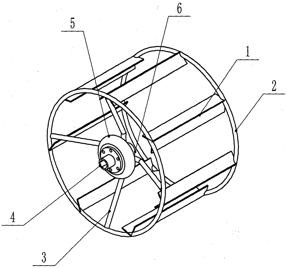
图1为本发明整体结构立体图。FIG. 1 is a perspective view of the overall structure of the present invention.
图2为本发明的主视图。FIG. 2 is a front view of the present invention.
图3为图2的A-A剖视图。FIG. 3 is a cross-sectional view taken along line A-A of FIG. 2 .
图4为图2的左视图。FIG. 4 is a left side view of FIG. 2 .
图5为本发明工作原理图。Fig. 5 is a working principle diagram of the present invention.
图6为本发明的铁轮图。Figure 6 is a diagram of the iron wheel of the present invention.
图7为本发明零件分解图。Figure 7 is an exploded view of the parts of the present invention.
在图1~图7中,增加磨擦力的V形叶片(1)、环形轮圈(2)、辐条(3)、内六角轴孔带螺栓孔的法兰(4)、弹性橡胶体(5)、圆柱形轴孔并且带螺栓孔的轮毂(6)、驱动轴(7)、铁轮(8)。In Figures 1 to 7, the friction-increasing V-shaped blade (1), the annular rim (2), the spokes (3), the hexagon socket flange with bolt holes (4), the elastic rubber body (5) ), cylindrical shaft hole and hub (6) with bolt holes, drive shaft (7), iron wheel (8).
具体实施方式:Detailed ways:
本发明的最佳实施例是这样的,参照图1至图7所示,一种能缓冲的农机行走轮,包括增加磨擦力的V形叶片1、环形轮圈2、辐条3、内六角轴孔带螺栓孔的法兰4、弹性橡胶体5、圆柱形轴孔并且带螺栓孔的轮毂6。由增加磨擦力的V形叶片1、环形轮圈2、辐条3、圆柱形轴孔并且带螺栓孔的轮毂6通过焊接组成铁轮8;弹性橡胶体5通过螺栓与铁轮8连接;内六角轴孔带螺栓孔的法兰4通过螺栓与弹性橡胶体5连接;由增加磨擦力的V形叶片1、环形轮圈2、辐条3、内六角轴孔带螺栓孔的法兰4、弹性橡胶体5、圆柱形轴孔并且带螺栓孔的轮毂6组合成的农机行走轮能经常性瞬间正反转。铁轮8只是农机行走轮其中的一种,铁轮8可由圆柱形轴孔并且带螺栓孔的轮毂6组合成其它的农机行走轮所代替。The preferred embodiment of the present invention is as follows. Referring to FIGS. 1 to 7 , a buffered agricultural machinery traveling wheel includes a V-
工作原理:一种能缓冲的农机行走轮,驱动轴7穿过内六角轴孔带螺栓孔的法兰4、弹性橡胶体5;驱动轴7啮合内六角轴孔带螺栓孔的法兰4;驱动轴7与圆柱形轴孔并且带螺栓孔的轮毂6间隙配合并且起到支承农机的作用,驱动轴7在圆柱形轴孔并且带螺栓孔的轮毂6的轴孔内相对旋转转动。如图5,正转动力B从驱动轴7输入驱动内六角轴孔带螺栓孔的法兰4,内六角轴孔带螺栓孔的法兰4驱动弹性橡胶体5,弹性橡胶体5驱动铁轮8正转;反转动力C从驱动轴7输入驱动内六角轴孔带螺栓孔的法兰4,内六角轴孔带螺栓孔的法兰4驱动弹性橡胶体5,弹性橡胶体5驱动铁轮8反转。在正转动力B和反转动力C的分别驱动下,驱动轴7通过弹性橡胶体5间接驱动铁轮8,由于弹性橡胶体5存在弹性,实现使铁轮8的从动滞后于正转动力B和反转动力C,起到缓冲的作用。当正转动力B驱动铁轮8正在进行正转动时,瞬间从正转动力B切换到反转动力C驱动铁轮8,这时弹性橡胶体5起到缓冲的作用,达到农机行走轮能瞬间正反转、保护好农机和农机行走轮不被破坏。Working principle: a kind of agricultural machinery walking wheel that can buffer, the
Claims (7)
Priority Applications (1)
| Application Number | Priority Date | Filing Date | Title |
|---|---|---|---|
| CN201910966671.6A CN110712476A (en) | 2019-09-30 | 2019-09-30 | Agricultural machinery walking wheel that can cushion |
Applications Claiming Priority (1)
| Application Number | Priority Date | Filing Date | Title |
|---|---|---|---|
| CN201910966671.6A CN110712476A (en) | 2019-09-30 | 2019-09-30 | Agricultural machinery walking wheel that can cushion |
Publications (1)
| Publication Number | Publication Date |
|---|---|
| CN110712476A true CN110712476A (en) | 2020-01-21 |
Family
ID=69212519
Family Applications (1)
| Application Number | Title | Priority Date | Filing Date |
|---|---|---|---|
| CN201910966671.6A Pending CN110712476A (en) | 2019-09-30 | 2019-09-30 | Agricultural machinery walking wheel that can cushion |
Country Status (1)
| Country | Link |
|---|---|
| CN (1) | CN110712476A (en) |
Citations (7)
| Publication number | Priority date | Publication date | Assignee | Title |
|---|---|---|---|---|
| GB350918A (en) * | 1929-12-17 | 1931-06-17 | Frederick William Baker | Improvements in or relating to wheels |
| CH155653A (en) * | 1931-09-29 | 1932-06-30 | Wettstein Oscar | Drive device for motor vehicles. |
| US5451001A (en) * | 1993-02-01 | 1995-09-19 | Kumm; Glen | Irrigation system tower support wheel |
| CN101746210A (en) * | 2010-01-21 | 2010-06-23 | 黎明恒 | Traveling wheel of farm machine |
| CN205238993U (en) * | 2015-12-03 | 2016-05-18 | 重庆华世丹机械制造有限公司 | Ferris wheel |
| CN208446148U (en) * | 2018-06-26 | 2019-02-01 | 魏红霞 | Plant seedlings trimmer for a kind of field |
| CN211869076U (en) * | 2019-09-30 | 2020-11-06 | 广西容县铁牛农机技术开发有限公司 | Agricultural machinery walking wheel that can cushion |
-
2019
- 2019-09-30 CN CN201910966671.6A patent/CN110712476A/en active Pending
Patent Citations (7)
| Publication number | Priority date | Publication date | Assignee | Title |
|---|---|---|---|---|
| GB350918A (en) * | 1929-12-17 | 1931-06-17 | Frederick William Baker | Improvements in or relating to wheels |
| CH155653A (en) * | 1931-09-29 | 1932-06-30 | Wettstein Oscar | Drive device for motor vehicles. |
| US5451001A (en) * | 1993-02-01 | 1995-09-19 | Kumm; Glen | Irrigation system tower support wheel |
| CN101746210A (en) * | 2010-01-21 | 2010-06-23 | 黎明恒 | Traveling wheel of farm machine |
| CN205238993U (en) * | 2015-12-03 | 2016-05-18 | 重庆华世丹机械制造有限公司 | Ferris wheel |
| CN208446148U (en) * | 2018-06-26 | 2019-02-01 | 魏红霞 | Plant seedlings trimmer for a kind of field |
| CN211869076U (en) * | 2019-09-30 | 2020-11-06 | 广西容县铁牛农机技术开发有限公司 | Agricultural machinery walking wheel that can cushion |
Similar Documents
| Publication | Publication Date | Title |
|---|---|---|
| CN211869076U (en) | Agricultural machinery walking wheel that can cushion | |
| FI3946998T3 (en) | Axle, in particular of a universal carrier frame | |
| CN202716956U (en) | Omnidirectional mobile crawler | |
| US2310735A (en) | Excavator | |
| KR101355287B1 (en) | axle assembly for a driving wheel of vehicle | |
| AR066187A1 (en) | OPERATING PROVISION TO PROMOTE AN IMPLEMENT IN A GROWING MACHINE | |
| CN211982706U (en) | Chassis combination structure of miniature harvester | |
| RU2430510C1 (en) | Multi-support sprinkler propulsor wheel | |
| CN202117984U (en) | Transmission structure of impeller and centrifugal compressor and air conditioner with transmission structure | |
| US10730586B2 (en) | Energy recovery system and method of power transmission | |
| US2809705A (en) | Propelling mechanism for lawn mowers | |
| CN204774377U (en) | Noiseless flower -drum | |
| CN204875744U (en) | Gyration trash cleaning machine drive chain | |
| CN209632755U (en) | Grinder walking mechanism | |
| CN204399311U (en) | A kind of two-wheeled vehicle crawler type walking mechanism | |
| CN217217456U (en) | Detachable and maintainable stalk chopper and ear-stalk harvesting corn harvester | |
| CN224161022U (en) | A snowplow | |
| CN204875739U (en) | Gyration trash cleaning machine tine harrow and drive chain's connection structure | |
| CN103947384A (en) | Grass raking device | |
| CN209634169U (en) | Agricultural push-pull cart and the traveling wheels used therefor | |
| CN206884600U (en) | A hub with a magnetic mechanical clutch tooth structure | |
| US619166A (en) | Crank | |
| US2007811A (en) | Adjustable tractor wheel | |
| US1128988A (en) | Tractor-wheel. | |
| JP3973093B2 (en) | Tread change device for traveling work machine |
Legal Events
| Date | Code | Title | Description |
|---|---|---|---|
| PB01 | Publication | ||
| PB01 | Publication | ||
| SE01 | Entry into force of request for substantive examination | ||
| SE01 | Entry into force of request for substantive examination | ||
| WD01 | Invention patent application deemed withdrawn after publication | ||
| WD01 | Invention patent application deemed withdrawn after publication |
Application publication date: 20200121 |