CN110712459A - Financial pen container - Google Patents
Financial pen container Download PDFInfo
- Publication number
- CN110712459A CN110712459A CN201810756099.6A CN201810756099A CN110712459A CN 110712459 A CN110712459 A CN 110712459A CN 201810756099 A CN201810756099 A CN 201810756099A CN 110712459 A CN110712459 A CN 110712459A
- Authority
- CN
- China
- Prior art keywords
- pen container
- face
- positioning column
- wall
- step face
- Prior art date
- Legal status (The legal status is an assumption and is not a legal conclusion. Google has not performed a legal analysis and makes no representation as to the accuracy of the status listed.)
- Pending
Links
- 238000007789 sealing Methods 0.000 claims description 6
- 238000001179 sorption measurement Methods 0.000 claims 1
- 239000003292 glue Substances 0.000 description 4
- 239000002184 metal Substances 0.000 description 4
- 230000000694 effects Effects 0.000 description 3
- 230000005484 gravity Effects 0.000 description 3
- 238000000034 method Methods 0.000 description 3
- 238000003466 welding Methods 0.000 description 3
- VYPSYNLAJGMNEJ-UHFFFAOYSA-N Silicium dioxide Chemical compound O=[Si]=O VYPSYNLAJGMNEJ-UHFFFAOYSA-N 0.000 description 2
- 230000009471 action Effects 0.000 description 2
- 230000008859 change Effects 0.000 description 2
- 238000003825 pressing Methods 0.000 description 2
- 230000008569 process Effects 0.000 description 2
- 239000000741 silica gel Substances 0.000 description 2
- 229910002027 silica gel Inorganic materials 0.000 description 2
- 238000010521 absorption reaction Methods 0.000 description 1
- 235000019994 cava Nutrition 0.000 description 1
- 230000007547 defect Effects 0.000 description 1
- 238000009434 installation Methods 0.000 description 1
- 238000004519 manufacturing process Methods 0.000 description 1
- 238000012986 modification Methods 0.000 description 1
- 230000004048 modification Effects 0.000 description 1
Images


Classifications
-
- B—PERFORMING OPERATIONS; TRANSPORTING
- B43—WRITING OR DRAWING IMPLEMENTS; BUREAU ACCESSORIES
- B43M—BUREAU ACCESSORIES NOT OTHERWISE PROVIDED FOR
- B43M99/00—Subject matter not provided for in other groups of this subclass
- B43M99/008—Desk-receptacles for holding writing appliances
Landscapes
- Details Of Rigid Or Semi-Rigid Containers (AREA)
Abstract
The invention discloses a financial pen container, wherein the lower end face of a container body is of a closed structure, a container cavity is arranged in the container body, the container cavity is opened on the upper end face of the container body, an annular primary step face and an annular secondary step face are sequentially arranged on the upper end face from inside to outside, the height of the primary step face is smaller than that of the upper end face, the height of the secondary step face is smaller than that of the primary step face, and pen inserting holes are respectively formed in the upper end face, the primary step face and the secondary step face; the bottom of the barrel is connected with a cylindrical bottom pillar, the lower end of the bottom pillar extends into the bottom tube, a transverse n-shaped adjusting groove is formed in the side wall of the bottom tube, a cylindrical positioning column is arranged on the outer wall of the lower portion of the bottom pillar, the central axis of the positioning column is perpendicular to the central axis of the bottom pillar, and the positioning column is arranged in the adjusting groove; the lower end of the bottom tube is connected with the upper surface of the bottom plate, the top plate positioned in the bottom tube is arranged below the bottom column, the spring is connected between the top plate and the upper surface of the bottom plate, the height of the pen container can be changed, and articles can be sorted in layers.
Description
Technical Field
The invention relates to the technical field of financial products, in particular to a pen container for finance.
Background
Finance broadly refers to financial activities and financial relationships. The former refers to the activity of enterprises involving funds in the production process and shows the form characteristics of finance, and the latter refers to the economic relationship between enterprises and all aspects in the financial activity and reveals the content essence of finance. Therefore, in summary, corporate finance is the movement of funds in the process of enterprise reproduction, and represents the economic relationship between enterprises and all aspects.
At present, along with the development of financial industry, people are also higher and higher to the requirement of the articles for use in the financial affairs work, the pen container that financial affairs were used commonly among the prior art, mostly be ordinary barrel structure, when articles such as pen in this pen container need be used to financial staff, if place when a lot of other debris blocked the pen container around the pen container, need the financial staff mostly with the hard mentioning of pen container in order to take its inside article, there is the loaded down with trivial details degree that increases financial staff's work, and this pen container also drops more easily taking up the in-process of putting down, lead to the unrestrained problem of its inside article.
Disclosure of Invention
According to the defects, the invention provides a pen container for finance, which is used for solving the problems that in the prior art, when a large number of objects are on a desktop, a finance worker needs to lift the pen container from the desktop to take the objects in the pen container, so that the work complexity of the finance worker is increased, and the pen container is easy to drop in the process of taking up and putting down, so that the objects in the pen container are scattered.
In order to achieve the purpose, the invention provides a financial pen container which comprises a container body, wherein the lower end face of the container body is of a closed structure, a container cavity is arranged in the container body, the container cavity is opened on the upper end face of the container body, an annular primary step face and an annular secondary step face are sequentially arranged on the upper end face from inside to outside, the height of the primary step face is smaller than that of the upper end face, the height of the secondary step face is smaller than that of the primary step face, and pen inserting holes are respectively formed in the upper end face, the primary step face and the secondary step face; the bottom of the barrel is connected with a cylindrical bottom pillar, the lower end of the bottom pillar extends into the bottom tube, a transverse n-shaped adjusting groove is formed in the side wall of the bottom tube, a cylindrical positioning column is arranged on the outer wall of the lower portion of the bottom pillar, the central axis of the positioning column is perpendicular to the central axis of the bottom pillar, and the positioning column is arranged in the adjusting groove; the lower end of the bottom tube is connected with the upper surface of the bottom plate, a top plate located in the bottom tube is arranged below the bottom column, and a spring is connected between the top plate and the upper surface of the bottom plate.
The pen container for finance disclosed by the invention can be used for comprising the following steps: when other objects on the desktop do not shield the pen container or do not need to use the objects in the pen container, the positioning column is arranged in the transverse part below the transverse n-shaped adjusting groove; when other objects on the desktop shield the pen container and the objects in the pen container need to be used, a financial staff holds the container body and rotates the container body, so that the positioning column moves into the longitudinal part of the transverse n-shaped adjusting groove from the transverse part below the transverse n-shaped adjusting groove, then the top plate pushes the bottom column upwards under the pushing action of the spring, the bottom column drives the container body to move upwards to raise the height, and then the financial staff rotates the container body reversely, so that the positioning column moves into the transverse part above the transverse n-shaped adjusting groove from the longitudinal part of the transverse n-shaped adjusting groove.
After the financial staff take the objects in the pen container, the barrel body can be rotated reversely again, so that the positioning column moves into the transverse part below the positioning column from the transverse part above the transverse n-shaped adjusting groove, the height of the pen container is reduced, the gravity center of the pen container is ensured to be at a lower position, the stability of the pen container during placement is improved, and the situation that the placement and taking of other objects on a desktop are influenced due to the overhigh height of the pen container is avoided.
The advantages of the invention are as follows:
according to the pen container for finance, the height of the pen container can be reduced when the objects in the pen container do not need to be taken at ordinary times, so that the gravity center of the pen container is kept stable, the situation that the pen container blocks the placement and the taking of other objects on a desktop is avoided, when the objects in the pen container need to be taken, the pen container does not need to be taken up or a finance person does not need to stand up, the finance person can rotate the pen container by stretching the hand to enable the height of the pen container to be increased, then the objects in the pen container can be taken, the working strength of the finance person can be reduced, the convenience and the comfort performance of use are improved, the accidents that the pen container falls off and the objects in the pen container fall off due to the fact that the pen container is taken for multiple times are avoided, and the use safety. Be provided with the cascaded high step face of multilayer on its up end to and be provided with the pen inserting hole of co-altitude not on the step face of difference, can make things convenient for financial staff to arrange in an order, place and take financial products by levels.
Drawings
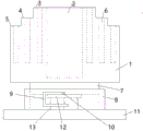
Fig. 1 is a front view of a fiscal pen container according to embodiment 1 of the present invention.
Fig. 2 is a top view of a fiscal pen container according to embodiment 1 of the present invention.
Fig. 3 is a front view of a fiscal pen container according to embodiment 2 of the present invention.
Description of reference numerals:
the pen holder is characterized in that the pen holder is a barrel body 1, a barrel cavity 2, an upper end face 3, a primary step face 4, a secondary step face 5, a pen inserting hole 6, a bottom column 7, a bottom tube 8, an adjusting groove 9, a positioning column 10, a bottom plate 11, a top plate 12, a spring 13, an opening and closing door 14, a hinge 15 and a handle 16.
Detailed Description
The following description of the embodiments of the present invention refers to the accompanying drawings and examples:
example 1:
a pen container for finance is disclosed, and is shown in figure 1, and comprises a container body 1, wherein the lower end face of the container body 1 is of a closed structure, a container cavity 2 is arranged in the container body 1, the container cavity 2 is opened on an upper end face 3 of the container body 1, an annular primary step face 4 and an annular secondary step face 5 are sequentially arranged on the upper end face 3 from inside to outside, the height of the primary step face 4 is smaller than that of the upper end face 3, the height of the secondary step face 5 is smaller than that of the primary step face 4, and referring to figure 2, pen inserting holes 6 are respectively formed in the upper end face 3, the primary step face 4 and the secondary step face 5; the bottom of the barrel body 1 is connected with a cylindrical bottom pillar 7, the lower end of the bottom pillar 7 extends into the bottom tube 8, a transverse n-shaped adjusting groove 9 is formed in the side wall of the bottom tube 8, a cylindrical positioning column 10 is arranged on the outer wall of the lower portion of the bottom pillar 7, the central axis of the positioning column 10 is perpendicular to the central axis of the bottom pillar 7, and the positioning column 10 is arranged in the adjusting groove 9; the lower end of the bottom tube 8 is connected with the upper surface of the bottom plate 11, a top plate 12 positioned in the bottom tube 8 is arranged below the bottom column 7, and a spring 13 is connected between the top plate 12 and the upper surface of the bottom plate 11.
The pen container for finance disclosed by the invention can be used for comprising the following steps: when other objects on the desktop do not shield the pen container or do not need to use the objects in the pen container, the positioning column 10 is arranged in the transverse part below the transverse n-shaped adjusting groove 9; when other objects on the desktop shield the pen container and the objects in the pen container need to be used, a financial staff holds the pen container 1 by hand and rotates the pen container 1, so that the positioning column 10 moves from the transverse part below the transverse n-shaped adjusting groove 9 to the longitudinal part of the transverse n-shaped adjusting groove 9, then the top plate 12 pushes the bottom column 7 upwards under the pushing action of the spring 13, so that the bottom column 7 drives the pen container 1 to move upwards to raise the height, and then the financial staff rotates the pen container 1 reversely, so that the positioning column 10 moves from the longitudinal part above the transverse n-shaped adjusting groove 9 to the transverse part above the transverse n-shaped adjusting groove.
After the financial staff take the articles in the pen container 1, the barrel body 1 can be rotated reversely again, so that the positioning column 10 moves from the transverse part above the transverse n-shaped adjusting groove 9 to the transverse part below the transverse n-shaped adjusting groove, the height of the pen container is reduced, the gravity center of the pen container is ensured to be at a lower position, the stability of the pen container in placement is improved, and the situation that the high height of the pen container affects the placement and taking of other articles on a desktop is avoided.
According to the financial pen container, the bottoms of the barrel cavity 2 and the pen inserting holes 6 can be set to be arc-shaped surfaces which are sunken downwards, the bottoms of the barrel cavity 2 and the pen inserting holes 6 can be provided with the protection pads, the protection pads can play a role in protecting pen points, the protection pads can be spongy pads, and the protection pads can be connected with the bottoms of the barrel cavity 2 and the pen inserting holes 6 through glue layers. The cylinder body 1 can be a cylinder or a square cylinder. The outer wall of the barrel body 1 can be provided with a rotary hand-holding ring, and the hand-holding ring can conveniently grip and rotate the barrel body 1. The gripping ring may be provided at the edge of the secondary step surface 5. The outer of the hand grasping ring can be sleeved with a hand grasping sleeve, and the hand grasping sleeve can improve the comfort when the hand grasping ring is grasped. The handheld sleeve can be provided with an opening seam, the handheld ring is escaped into the handheld sleeve through the opening seam, the handheld sleeve can be provided with a zipper or a snap fastener structure at the opening seam, the handheld sleeve can form an annular sleeve-shaped structure through the zipper or the snap fastener combination structure after the handheld ring is escaped into the handheld sleeve through the opening seam, and the handheld sleeve is sleeved outside the handheld ring. The upper end surface 3, the primary step surface 4 and the secondary step surface 5 can be arranged to be arc surfaces protruding upwards. The bottom column 7 can be of an integrated structure with the cylinder body 1, and the bottom column 7 can also be a metal piece connected with the cylinder body 1 through a welding structure. The bottom tube 8 and the bottom plate 11 can be of an integrated structure, and the bottom tube 8 and the bottom plate 11 can also be metal pieces connected through a welding structure. When installing the bottom pillar 7 in the bottom tube 8 and installing the positioning column 10 on the bottom pillar 7, can stretch into the bottom tube 8 with the bottom pillar 7 earlier, then weld the positioning column 10 on the outer wall of bottom pillar 7 in the horizontal "n" font adjustment tank 9, also can be provided with the internal thread hole on the bottom pillar 7, and set up the external screw thread that matches in this internal thread hole in the tip of positioning column 10, then stretch into the bottom tube 8 with the bottom pillar 7 in the back, rotate this internal thread hole of bottom pillar 7 to horizontal "n" font adjustment tank 9 department, then with the external screw thread of positioning column 10 and this internal thread hole cooperation, rotate positioning column 10 to this internal thread downthehole in order to be connected with the bottom pillar 7. Alternatively, the top plate 12, the spring 13 and the bottom plate 11 may be provided as metal pieces, and then the spring 13 may be connected to the top plate 12 and the bottom plate 11 by a welding structure before the bottom pillar 7 is inserted into the bottom pipe 8.
Example 2:
a financial pen container is similar to the financial pen container in the embodiment 1, except that referring to fig. 3, a through hole type door hole is formed in the side wall, located in a container cavity 2, of a container body 1, an opening and closing door 14 is arranged in the door hole, the opening and closing door 14 is connected with the side wall of the container body 1 through a hinge 15, and a handle 16 is arranged on the opening and closing door 14. Therefore, when the article taking device is used, when the article such as a rubber and the like positioned at the bottom of the barrel cavity 2 needs to be taken, the rest of the article at the upper part in the barrel cavity 2 does not need to be taken out firstly, and the article positioned at the bottom of the barrel cavity 2 can be taken out only by opening the opening and closing door 14, so that the use efficiency is improved. The handle 16 and the opening and closing door 14 may be provided as metal pieces connected by a welded structure.
Still further, the barrel 1 is a cylinder, and the opening and closing door 14 is an arc-shaped plate structure. This facilitates the installation of the opening and closing door 14.
It is still further possible that the edge of the opening and closing door 14 is provided with a rubber sealing strip. This improves the sealing property when the opening/closing door 14 is closed. The rubber sealing strip can be replaced by a silica gel strip. The rubber sealing strip and the silica gel strip can be connected with the edge of the opening and closing door 14 through the glue layer.
It is also possible that the edge of the door opening and closing 14 and the door hole are provided with magnetic strips which are mutually connected in an absorption manner. This improves the sealing property when the opening/closing door 14 is closed. The magnetic strip may be connected to the opening and closing door 14 and the edge of the door opening by a glue layer. Alternatively, the opening and closing door 14 and the edge of the door hole may be respectively provided with an embedded groove, and the magnetic strip may be disposed in the embedded groove. Meanwhile, the magnetic stripe can also be connected with the groove surface of the embedded groove through the glue layer.
Still further, the outer wall of the positioning column 10 is set as a magnetic surface, and the end groove surfaces of the transverse parts above and below the transverse n-shaped adjusting groove 9 are set as magnetic surfaces. Therefore, when the positioning column 10 rotates, the groove surfaces at the end parts of the transverse parts above and below the other transverse n-shaped adjusting grooves 9 can be adsorbed and fixed conveniently, and the stability of the pen container during height change is improved.
It should be noted that, no matter whether the outer wall of the positioning column 10 and the end groove surfaces of the transverse parts above and below the transverse n-shaped adjusting groove 9 are set as magnetic surfaces, when the financial staff rotates the pen container to change the height thereof, the left end or the right end of the transverse part of the upper surface and the lower surface of the transverse n-shaped adjusting groove 9 can be judged by the sense that the barrel 1 can not be rotated continuously, and the left end or the right end of the transverse part of the transverse n-shaped adjusting groove 9 can be judged by matching with the memory or observation of the opening direction of the transverse n-shaped adjusting groove 9, or the trial of pressing the cylinder 1 up and down can judge whether the positioning column 10 is positioned in the longitudinal part of the horizontal n-shaped adjusting groove 9, namely, whether the height of the pen container can be changed by lifting or pressing the barrel body 1 downwards can be judged, and the next rotation positioning operation is carried out.
Still further, a magnetic surface of the outer wall of the positioning column 10 is provided with a tubular magnetic sleeve, and the magnetic sleeve is sleeved outside the positioning column 10. This facilitates the mounting of the magnetic sleeve and the positioning post 10.
Still further, be provided with the internal thread on the inner wall of magnetic sleeve, be provided with on the outer wall of reference column 10 with the external screw thread that the internal thread matches, the magnetic sleeve passes through the internal thread with the external screw thread is connected with reference column 10. This facilitates the mounting of the magnetic sleeve and the positioning post 10.
It can be further that be provided with on the inner wall of magnetic force cover to the bellied draw runner of inboard, be provided with on the outer wall of reference column 10 with the spout that the draw runner matches, the magnetic force cover passes through the draw runner slides in be connected with reference column 10 in the spout. This facilitates the mounting of the magnetic sleeve and the positioning post 10.
Note that, the sliding groove is opened at the end of the positioning post 10, so that the slide bar can smoothly slide into the sliding groove.
It can be further that, be provided with the spout that caves in to the outside on the inner wall of magnetic sleeve, be provided with on the outer wall of reference column 10 with the draw runner that the spout matches, reference column 10 passes through the draw runner slides in the spout with the magnetic sleeve is connected. This facilitates the mounting of the magnetic sleeve and the positioning post 10.
It should be noted that, the sliding groove is opened at the end of the magnetic sleeve, so that the sliding strip can slide into the sliding groove smoothly.
In addition, the number of the pen inserting holes 6 can be multiple and is evenly distributed. The top plate 12 is in contact with the bottom surface of the bottom pillar 7, and the top plate 12 may be disposed in a concentric configuration with the bottom surface of the bottom pillar 7.
Although the preferred embodiments of the present invention have been described in detail with reference to the accompanying drawings, the present invention is not limited to the above embodiments, and various changes can be made within the knowledge of those skilled in the art without departing from the spirit of the present invention.
Many other changes and modifications can be made without departing from the spirit and scope of the invention. It is to be understood that the invention is not to be limited to the specific embodiments, but only by the scope of the appended claims.
Claims (10)
1. A financial pen container comprises a container body (1), the lower end face of the container body (1) is of a closed structure, a container cavity (2) is arranged in the container body (1), the container cavity (2) is opened on the upper end face (3) of the container body (1), the financial pen container is characterized in that an annular primary step face (4) and a secondary step face (5) are sequentially arranged on the upper end face (3) from inside to outside, the height of the primary step face (4) is smaller than that of the upper end face (3), the height of the secondary step face (5) is smaller than that of the primary step face (4), and pen inserting holes (6) are respectively formed in the upper end face (3), the primary step face (4) and the secondary step face (5); the bottom of the barrel body (1) is connected with a cylindrical bottom column (7), the lower end of the bottom column (7) extends into the bottom tube (8), the side wall of the bottom tube (8) is provided with a transverse n-shaped adjusting groove (9), the outer wall of the lower part of the bottom column (7) is provided with a cylindrical positioning column (10), the central axis of the positioning column (10) is vertical to the central axis of the bottom column (7), and the positioning column (10) is arranged in the adjusting groove (9); the lower end of the bottom pipe (8) is connected with the upper surface of the bottom plate (11), a top plate (12) positioned in the bottom pipe (8) is arranged below the bottom column (7), and a spring (13) is connected between the top plate (12) and the upper surface of the bottom plate (11).
2. The financial pen container according to claim 1, wherein a through hole type door hole is formed in the side wall, located in the container cavity (2), of the container body (1), an opening and closing door (14) is arranged in the door hole, the opening and closing door (14) is connected with the side wall of the container body (1) through a hinge (15), and a handle (16) is arranged on the opening and closing door (14).
3. The financial pen container according to claim 2, wherein the container body (1) is a cylinder, and the opening and closing door (14) is of an arc-shaped plate structure.
4. The financial pen container according to claim 2, wherein a rubber sealing strip is arranged at the edge of the opening and closing door (14).
5. The financial pen container according to claim 2, wherein the edges of the opening and closing door (14) and the door hole are provided with magnetic stripes which are mutually connected in an adsorption manner.
6. The fiscal pen container according to claim 1, characterized in that the outer wall of the positioning post (10) is provided with a magnetic surface, and the end groove surfaces of the transverse parts above and below the transverse n-shaped adjusting groove (9) are provided with magnetic surfaces.
7. The financial pen container according to claim 6, wherein the magnetic surface of the outer wall of the positioning column (10) is provided with a tubular magnetic sleeve, and the magnetic sleeve is arranged outside the positioning column (10).
8. The financial pen container as claimed in claim 7, wherein an inner thread is arranged on the inner wall of the magnetic sleeve, an outer thread matched with the inner thread is arranged on the outer wall of the positioning column (10), and the magnetic sleeve is connected with the positioning column (10) through the inner thread and the outer thread.
9. The financial pen container according to claim 7, wherein a slide bar protruding towards the inside is arranged on the inner wall of the magnetic sleeve, a sliding groove matched with the slide bar is arranged on the outer wall of the positioning column (10), and the magnetic sleeve slides into the sliding groove through the slide bar and is connected with the positioning column (10).
10. The financial pen container according to claim 7, wherein the inner wall of the magnetic sleeve is provided with a sliding groove which is recessed towards the outside, the outer wall of the positioning column (10) is provided with a sliding strip which is matched with the sliding groove, and the positioning column (10) slides into the sliding groove through the sliding strip and is connected with the magnetic sleeve.
Priority Applications (1)
| Application Number | Priority Date | Filing Date | Title |
|---|---|---|---|
| CN201810756099.6A CN110712459A (en) | 2018-07-11 | 2018-07-11 | Financial pen container |
Applications Claiming Priority (1)
| Application Number | Priority Date | Filing Date | Title |
|---|---|---|---|
| CN201810756099.6A CN110712459A (en) | 2018-07-11 | 2018-07-11 | Financial pen container |
Publications (1)
| Publication Number | Publication Date |
|---|---|
| CN110712459A true CN110712459A (en) | 2020-01-21 |
Family
ID=69208902
Family Applications (1)
| Application Number | Title | Priority Date | Filing Date |
|---|---|---|---|
| CN201810756099.6A Pending CN110712459A (en) | 2018-07-11 | 2018-07-11 | Financial pen container |
Country Status (1)
| Country | Link |
|---|---|
| CN (1) | CN110712459A (en) |
Citations (17)
| Publication number | Priority date | Publication date | Assignee | Title |
|---|---|---|---|---|
| CN201833798U (en) * | 2010-09-26 | 2011-05-18 | 山东科技大学 | Pen container with adjustable height |
| CN201900920U (en) * | 2010-12-17 | 2011-07-20 | 杭州市余杭区塘栖第二中学 | Lifting pen holder |
| CN201931898U (en) * | 2011-01-04 | 2011-08-17 | 谢雯雯 | Telescopic pen container |
| CN202703058U (en) * | 2012-07-04 | 2013-01-30 | 王思远 | Improved pen container |
| CN203093568U (en) * | 2013-01-24 | 2013-07-31 | 田云慧 | Pen holder with adjustable height |
| CN103287177A (en) * | 2013-03-26 | 2013-09-11 | 蔡洪平 | Pen container |
| CN104691191A (en) * | 2013-12-08 | 2015-06-10 | 西安凯倍耐特智能工程有限公司 | Novel pen container |
| CN204488342U (en) * | 2014-12-30 | 2015-07-22 | 钟子岚 | Adjustable pen container |
| CN204978000U (en) * | 2015-06-26 | 2016-01-20 | 景宁山凤皇工艺制品有限公司 | Can be as pen container of desk lamp |
| CN205344270U (en) * | 2015-12-24 | 2016-06-29 | 沈璐涵 | Pen container that bobbin base can go up and down fast |
| CN205661222U (en) * | 2016-04-06 | 2016-10-26 | 郑贝贝 | Pen holder |
| CN106240209A (en) * | 2016-08-31 | 2016-12-21 | 田玉 | A kind of pen container with protection nib function |
| CN206049167U (en) * | 2016-08-25 | 2017-03-29 | 崔子今 | A kind of scalable pen container |
| CN206336036U (en) * | 2016-08-19 | 2017-07-18 | 战怡红 | It is layered pen container |
| CN206614978U (en) * | 2017-02-25 | 2017-11-07 | 国佳丽 | Fine arts paintbrush stores device |
| CN108068517A (en) * | 2016-11-14 | 2018-05-25 | 刘中昊 | A kind of pen container |
| CN108081839A (en) * | 2018-01-23 | 2018-05-29 | 温州市乐西科技有限公司 | A kind of novel student pen container |
-
2018
- 2018-07-11 CN CN201810756099.6A patent/CN110712459A/en active Pending
Patent Citations (17)
| Publication number | Priority date | Publication date | Assignee | Title |
|---|---|---|---|---|
| CN201833798U (en) * | 2010-09-26 | 2011-05-18 | 山东科技大学 | Pen container with adjustable height |
| CN201900920U (en) * | 2010-12-17 | 2011-07-20 | 杭州市余杭区塘栖第二中学 | Lifting pen holder |
| CN201931898U (en) * | 2011-01-04 | 2011-08-17 | 谢雯雯 | Telescopic pen container |
| CN202703058U (en) * | 2012-07-04 | 2013-01-30 | 王思远 | Improved pen container |
| CN203093568U (en) * | 2013-01-24 | 2013-07-31 | 田云慧 | Pen holder with adjustable height |
| CN103287177A (en) * | 2013-03-26 | 2013-09-11 | 蔡洪平 | Pen container |
| CN104691191A (en) * | 2013-12-08 | 2015-06-10 | 西安凯倍耐特智能工程有限公司 | Novel pen container |
| CN204488342U (en) * | 2014-12-30 | 2015-07-22 | 钟子岚 | Adjustable pen container |
| CN204978000U (en) * | 2015-06-26 | 2016-01-20 | 景宁山凤皇工艺制品有限公司 | Can be as pen container of desk lamp |
| CN205344270U (en) * | 2015-12-24 | 2016-06-29 | 沈璐涵 | Pen container that bobbin base can go up and down fast |
| CN205661222U (en) * | 2016-04-06 | 2016-10-26 | 郑贝贝 | Pen holder |
| CN206336036U (en) * | 2016-08-19 | 2017-07-18 | 战怡红 | It is layered pen container |
| CN206049167U (en) * | 2016-08-25 | 2017-03-29 | 崔子今 | A kind of scalable pen container |
| CN106240209A (en) * | 2016-08-31 | 2016-12-21 | 田玉 | A kind of pen container with protection nib function |
| CN108068517A (en) * | 2016-11-14 | 2018-05-25 | 刘中昊 | A kind of pen container |
| CN206614978U (en) * | 2017-02-25 | 2017-11-07 | 国佳丽 | Fine arts paintbrush stores device |
| CN108081839A (en) * | 2018-01-23 | 2018-05-29 | 温州市乐西科技有限公司 | A kind of novel student pen container |
Similar Documents
| Publication | Publication Date | Title |
|---|---|---|
| CN210311484U (en) | Kit convenient to deposit | |
| CN210388818U (en) | Polishing clamp for cover plate | |
| KR101414167B1 (en) | Dent restoration device | |
| CN203679701U (en) | Valve rod assembly screwing device | |
| CN211008080U (en) | Spring bolt for baby bed | |
| CN211732139U (en) | Novel beverage storage box | |
| CN211021408U (en) | Intelligent liftable office furniture | |
| CN210604231U (en) | An integrated Mohs hardness pen | |
| CN201031870Y (en) | Improved structure of suction cup | |
| CN205147726U (en) | Stable buffering righting device | |
| CN210672378U (en) | Resistance to compression suitcase with article classification places | |
| CN208842092U (en) | A kind of drawing tool of urban and rural planning design | |
| US2277945A (en) | Wrench | |
| CN206598265U (en) | A kind of novel wagon tool container | |
| CN213104293U (en) | Double-lug supporting plate assembly riveting tool | |
| CN212146337U (en) | Workpiece placing device | |
| CN222062527U (en) | Packing box unpacking device | |
| CN204610458U (en) | Fixing device | |
| CN207461660U (en) | Lift cosmetic pencil | |
| CN206137532U (en) | Multifunctional painting desk | |
| CN206656022U (en) | A kind of ball valve | |
| CN211673655U (en) | A multifunctional portable toolbox | |
| CN215271649U (en) | Intelligent bed with turnover bed board | |
| CN205034772U (en) | Handheld extracting device that hangs of rotation cell type mechanism | |
| CN115782447B (en) | Credit rating device for enterprises |
Legal Events
| Date | Code | Title | Description |
|---|---|---|---|
| PB01 | Publication | ||
| PB01 | Publication | ||
| SE01 | Entry into force of request for substantive examination | ||
| SE01 | Entry into force of request for substantive examination | ||
| RJ01 | Rejection of invention patent application after publication |
Application publication date: 20200121 |
|
| RJ01 | Rejection of invention patent application after publication |