CN110696956A - a steering mechanism - Google Patents
a steering mechanism Download PDFInfo
- Publication number
- CN110696956A CN110696956A CN201911087352.4A CN201911087352A CN110696956A CN 110696956 A CN110696956 A CN 110696956A CN 201911087352 A CN201911087352 A CN 201911087352A CN 110696956 A CN110696956 A CN 110696956A
- Authority
- CN
- China
- Prior art keywords
- front fork
- linkage
- friction surface
- piece
- steering
- Prior art date
- Legal status (The legal status is an assumption and is not a legal conclusion. Google has not performed a legal analysis and makes no representation as to the accuracy of the status listed.)
- Granted
Links
Images



Classifications
-
- B—PERFORMING OPERATIONS; TRANSPORTING
- B62—LAND VEHICLES FOR TRAVELLING OTHERWISE THAN ON RAILS
- B62K—CYCLES; CYCLE FRAMES; CYCLE STEERING DEVICES; RIDER-OPERATED TERMINAL CONTROLS SPECIALLY ADAPTED FOR CYCLES; CYCLE AXLE SUSPENSIONS; CYCLE SIDECARS, FORECARS, OR THE LIKE
- B62K21/00—Steering devices
-
- B—PERFORMING OPERATIONS; TRANSPORTING
- B62—LAND VEHICLES FOR TRAVELLING OTHERWISE THAN ON RAILS
- B62K—CYCLES; CYCLE FRAMES; CYCLE STEERING DEVICES; RIDER-OPERATED TERMINAL CONTROLS SPECIALLY ADAPTED FOR CYCLES; CYCLE AXLE SUSPENSIONS; CYCLE SIDECARS, FORECARS, OR THE LIKE
- B62K21/00—Steering devices
- B62K21/02—Front wheel forks or equivalent, e.g. single tine
Landscapes
- Engineering & Computer Science (AREA)
- Mechanical Engineering (AREA)
- Steering Devices For Bicycles And Motorcycles (AREA)
Abstract
本发明公开了一种转向机构,包括:车架、转向杆、前叉、联动件及锁紧机构,所述前叉与转向杆固定连接,所述前叉与车架之间形成可相对转动连接,所述联动件活动安装于前叉或转向杆或车架上,所述车架、前叉及转向杆三者之一与联动件设有相互配合的摩擦面,转向杆不转动时,联动件的摩擦面在锁紧机构的作用下与车架或前叉或转向杆上的摩擦面相抵接,转向杆需要转动时,拨动锁紧机构,使联动件的摩擦面与车架或前叉或转向杆上的摩擦面相松开的同时,转向杆带动前叉转动,从而大大提高了骑行的安全性能。

The invention discloses a steering mechanism, comprising: a vehicle frame, a steering rod, a front fork, a linkage and a locking mechanism. The front fork is fixedly connected with the steering rod, and the front fork and the vehicle frame are formed to be relatively rotatable. The linkage is movably installed on the front fork, the steering rod or the frame, and one of the frame, the front fork and the steering rod and the linkage are provided with friction surfaces that cooperate with each other. When the steering rod does not rotate, The friction surface of the linkage is in contact with the friction surface of the frame or front fork or steering rod under the action of the locking mechanism. When the steering rod needs to be rotated, the locking mechanism is toggled to make the friction surface of the linkage and the frame or When the friction surfaces on the front fork or the steering rod are loosened, the steering rod drives the front fork to rotate, thereby greatly improving the safety performance of riding.
Description
【技术领域】【Technical field】
本发明涉及自行车领域,尤其涉及一种转向机构。The invention relates to the field of bicycles, in particular to a steering mechanism.
【背景技术】【Background technique】
自行车一般包括车架、转向机构、踩踏机构、前叉、后叉、前轮及后轮,现有技术中的自行车有前驱自行车跟后驱自行车,所谓前驱自行车即踩踏机构直接驱动前轮,后轮跟转,所谓后驱自行车即踩踏机构直接驱动后轮,前轮跟转,众所周知,自行车的转向机构一般设置于前叉的上方,如果是后驱自行车的话,由于转向机构在前,踩踏机构在后,因此在后的踩踏机构在踩踏时仅对前面的转向机构造成较小的干扰,如果是前驱自行车的话,由于转向机构跟踩踏机构同时位于自行车的前方,因此踩踏机构在踩踏时会有一个力作用于转向机构上,使转向机构左右晃动,而转向机构设置的初衷不仅仅是在需要转向时起到转向作用,在车辆正常骑行时还需要转向机构不受踩踏机构的干扰,从而避免转向机构在车辆正常骑行时左右晃动,给骑行带来安全隐患。A bicycle generally includes a frame, a steering mechanism, a pedaling mechanism, a front fork, a rear fork, a front wheel and a rear wheel. The bicycles in the prior art include a front-drive bicycle and a rear-drive bicycle. The so-called front-drive bicycle means that the pedaling mechanism directly drives the front wheel, and the rear The so-called rear-drive bicycle means that the pedaling mechanism directly drives the rear wheel, and the front wheel rotates with it. As we all know, the steering mechanism of the bicycle is generally set above the front fork. In the rear, the pedaling mechanism at the rear only causes less interference to the steering mechanism in front when pedaling. If it is a front-wheel drive bicycle, since the steering mechanism and the pedaling mechanism are located in the front of the bicycle at the same time, the pedaling mechanism will have some problems when pedaling. A force acts on the steering mechanism, causing the steering mechanism to sway left and right. The original intention of the steering mechanism is not only to play a steering role when steering is required, but also to prevent the steering mechanism from being disturbed by the pedaling mechanism when the vehicle is riding normally. Avoid the steering mechanism from shaking left and right when the vehicle is riding normally, which will bring safety hazards to riding.
因此,有必要提供一种解决上述技术问题的转向机构。Therefore, it is necessary to provide a steering mechanism that solves the above technical problems.
【发明内容】[Content of the invention]
为解决上述技术问题,本发明的目的在于提供一种结构简单、安装方便的转向机构。In order to solve the above technical problems, the purpose of the present invention is to provide a steering mechanism with simple structure and convenient installation.
本发明所采用的技术方案为:一种转向机构,包括:车架、转向杆、前叉、联动件及锁紧机构,所述前叉与转向杆固定连接,所述前叉与车架之间形成可相对转动连接,所述联动件活动安装于前叉或转向杆或车架上,所述车架、前叉及转向杆三者之一与联动件设有相互配合的摩擦面,转向杆不转动时,联动件的摩擦面在锁紧机构的作用下与车架或前叉或转向杆上的摩擦面相抵接,转向杆需要转动时,拨动锁紧机构,使联动件的摩擦面与车架或前叉或转向杆上的摩擦面相松开的同时,转向杆带动前叉转动。The technical scheme adopted in the present invention is: a steering mechanism, comprising: a frame, a steering rod, a front fork, a linkage and a locking mechanism, the front fork and the steering rod are fixedly connected, and the front fork and the frame are connected A relatively rotatable connection is formed between them, the linkage is movably installed on the front fork, the steering rod or the frame, and one of the frame, the front fork and the steering rod is provided with a friction surface that cooperates with the linkage, and the steering When the rod does not rotate, the friction surface of the linkage is in contact with the friction surface of the frame, front fork or steering rod under the action of the locking mechanism. When the steering rod needs to be rotated, the locking mechanism is toggled to make the friction of the linkage. When the friction surface is released from the frame or front fork or steering rod, the steering rod drives the front fork to rotate.
优选地,本发明中的一种转向机构进一步设置为:所述前叉包括前叉主体部及与前叉主体部固定连接的前叉竖轴,所述车架包括车架主体部及与车架主体部固定连接的安装座。Preferably, a steering mechanism in the present invention is further configured as follows: the front fork comprises a front fork main body part and a front fork vertical shaft fixedly connected with the front fork main body part; The mounting seat fixedly connected to the main body of the frame.
优选地,本发明中的一种转向机构进一步设置为:所述前叉竖轴安装于安装座内,所述安装座沿径向向外凸设有凸台,所述凸台内设有用于收容联动件的收容腔,所述车架的摩擦面设置于所述凸台的收容腔的腔壁上,所述前叉竖轴上设有与联动件相配合的孔,所述联动件活动安装于所述孔内,所述联动件的摩擦面设置于联动件的外侧面上或者设置于联动件的上、下表面上。Preferably, a steering mechanism in the present invention is further configured as follows: the front fork vertical shaft is installed in a mounting seat, the mounting seat is radially outwardly provided with a boss, and the boss is provided with a The accommodating cavity for accommodating the linkage, the friction surface of the frame is arranged on the cavity wall of the accommodating cavity of the boss, the vertical shaft of the front fork is provided with a hole for matching with the linkage, and the linkage moves Installed in the hole, the friction surface of the linkage member is arranged on the outer side surface of the linkage member or on the upper and lower surfaces of the linkage member.
优选地,本发明中的一种转向机构进一步设置为:所述联动件上的摩擦面包括设置于联动件上表面上的第一摩擦面及设置于联动件下表面上的第二摩擦面,所述凸台的收容腔的腔壁上的摩擦面包括第三摩擦面及第四摩擦面,所述第一摩擦面与第三摩擦面相配合从而形成第一组配合面,所述第二摩擦面与第四摩擦面相配合从而形成第二组配合面,所述第一组配合面与第二组配合面两者中,至少一组配合面为圆锥面配合。Preferably, a steering mechanism in the present invention is further configured as follows: the friction surface on the linkage member includes a first friction surface disposed on the upper surface of the linkage member and a second friction surface disposed on the lower surface of the linkage member, The friction surface on the cavity wall of the receiving cavity of the boss includes a third friction surface and a fourth friction surface. The first friction surface cooperates with the third friction surface to form a first set of matching surfaces, and the second friction surface cooperates with the third friction surface. The surface cooperates with the fourth friction surface to form a second set of matching surfaces, and among the first set of matching surfaces and the second set of matching surfaces, at least one set of matching surfaces is conical.
优选地,本发明中的一种转向机构进一步设置为:所述前叉竖轴上设有连接件,所述联动件设置于安装座的外侧,所述联动件的摩擦面设置于联动件的内侧壁上,所述车架上的摩擦面设置于安装座的外侧壁上,所述联动件的一端与连接件活动连接,所述联动件的另一端与锁紧机构相连接。Preferably, a steering mechanism in the present invention is further configured as follows: a connecting piece is arranged on the vertical shaft of the front fork, the linking piece is arranged on the outer side of the mounting seat, and the friction surface of the linking piece is arranged on the outer side of the linking piece. On the inner side wall, the friction surface on the frame is arranged on the outer side wall of the mounting seat, one end of the linking piece is movably connected with the connecting piece, and the other end of the linking piece is connected with the locking mechanism.
优选地,本发明中的一种转向机构进一步设置为:所述安装座上设有连接件,所述联动件设置于前叉竖轴的外侧,所述联动件的摩擦面设置于联动件的内侧壁上,所述前叉上的摩擦面设置于前叉竖轴的外侧壁上,所述联动件的一端与连接件活动连接,所述联动件的另一端与锁紧机构相连接。Preferably, a steering mechanism in the present invention is further configured as follows: a connecting piece is arranged on the mounting seat, the linking piece is arranged on the outer side of the vertical shaft of the front fork, and the friction surface of the linking piece is arranged on the side of the linking piece. On the inner side wall, the friction surface on the front fork is arranged on the outer side wall of the vertical shaft of the front fork, one end of the linking piece is movably connected with the connecting piece, and the other end of the linking piece is connected with the locking mechanism.
优选地,本发明中的一种转向机构进一步设置为:所述锁紧机构包括与联动件相配合的锁紧头、弹簧、解锁件及弹簧挡件,所述解锁件为拉杆或拉绳,所述锁紧头的一端与解锁件固定连接,所述锁紧头的另一端与联动件相配合,所述弹簧的一端与锁紧头相抵接,所述弹簧的另一端与弹簧挡件相抵接。Preferably, a steering mechanism in the present invention is further configured as follows: the locking mechanism includes a locking head, a spring, an unlocking member and a spring stopper matched with the linkage member, and the unlocking member is a pull rod or a pull rope, One end of the locking head is fixedly connected with the unlocking piece, the other end of the locking head is matched with the linkage piece, one end of the spring is abutted with the locking head, and the other end of the spring is abutted against the spring stopper catch.
优选地,本发明中的一种转向机构进一步设置为:所述锁紧机构包括压簧及解锁件,所述联动件的数量为两个,所述压簧的一端与其中一个联动件相抵接,所述压簧的另一端与另一个联动件相抵接,所述解锁件包括:拉丝、套设于拉丝上的软性套管及设置于软性套管两端的金属件。Preferably, a steering mechanism in the present invention is further configured as follows: the locking mechanism includes a compression spring and an unlocking member, the number of the linkage members is two, and one end of the compression spring abuts against one of the linkage members , the other end of the compression spring is in contact with another linkage piece, and the unlocking piece includes: a drawing wire, a soft sleeve sleeved on the drawing wire, and a metal piece arranged at both ends of the soft sleeve.
优选地,本发明中的一种转向机构进一步设置为:所述锁紧机构包括弹簧、解锁件及弹簧挡件,所述联动件的数量为一个,所述解锁件为拉杆或拉绳,所述弹簧的一端与联动件相抵接,所述弹簧的另一端与弹簧挡件相抵接。Preferably, a steering mechanism in the present invention is further configured as follows: the locking mechanism includes a spring, an unlocking member and a spring stopper, the number of the linking member is one, and the unlocking member is a pull rod or a pull rope, so One end of the spring is in contact with the linkage member, and the other end of the spring is in contact with the spring stopper.
优选地,本发明中的一种转向机构进一步设置为:所述转向杆上设有转向把手。Preferably, a steering mechanism in the present invention is further configured as follows: a steering handle is provided on the steering rod.
与现有技术相比,本发明具有如下有益效果:本发明通过一系列的结构设计使得转向机构实现:当前轮不需要转向时,前叉、转向杆与车架相固持,当前轮需要转向时,前叉、转向杆与车架相松开,从而可避免车辆在正常行驶时踩踏机构对转向机构造成干扰,大大提高了骑行的安全性能。Compared with the prior art, the present invention has the following beneficial effects: the present invention enables the steering mechanism to be realized through a series of structural designs: when the front wheel does not need to be turned, the front fork, the steering rod and the frame are held together, and when the front wheel needs to be turned , the front fork, the steering rod and the frame are released, so as to avoid the interference of the pedaling mechanism to the steering mechanism when the vehicle is running normally, and greatly improve the safety performance of riding.
【附图说明】【Description of drawings】
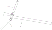
图1是本发明实施例1中转向机构的立体结构示意图。FIG. 1 is a schematic three-dimensional structure diagram of a steering mechanism in
图2是本发明实施例1中转向机构的分解结构示意图。FIG. 2 is a schematic diagram of an exploded structure of the steering mechanism in
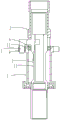
图3是本发明实施例1中转向机构的剖视结构示意图。3 is a schematic cross-sectional structural diagram of the steering mechanism in
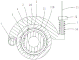
图4是本发明实施例2中转向机构的剖视结构示意图。4 is a schematic cross-sectional structural diagram of the steering mechanism in
图5是本发明实施例2中锁紧机构与联动件的安装结构示意图。FIG. 5 is a schematic diagram of the installation structure of the locking mechanism and the linkage in
图6是本发明实施例3中锁紧机构与联动件的安装结构示意图。FIG. 6 is a schematic diagram of the installation structure of the locking mechanism and the linkage in Embodiment 3 of the present invention.
图1至图3中:1、车架,10、车架主体部,11、安装座,110、凸台,111、收容腔,1110、第三摩擦面,1111、第四摩擦面,2、转向杆,20、车把手,3、前叉,30、前叉主体部,31、前叉竖轴,310、孔,4、联动件,40、第一摩擦面,41、第二摩擦面,5、锁紧机构,50、锁紧头,51、弹簧,52、解锁件,53、弹簧挡件,6、轴承。In Figures 1 to 3: 1. Frame, 10, Frame body, 11, Mounting seat, 110, Boss, 111, Receiving cavity, 1110, Third friction surface, 1111, Fourth friction surface, 2, Steering rod, 20, handlebar, 3, front fork, 30, front fork body, 31, front fork vertical shaft, 310, hole, 4, linkage, 40, first friction surface, 41, second friction surface, 5, locking mechanism, 50, locking head, 51, spring, 52, unlocking piece, 53, spring stopper, 6, bearing.
图4至图5中:1、车架,11、安装座,110、第二摩擦面,2、转向杆,3、前叉,31、前叉竖轴,4、联动件,40、第一摩擦面,5、锁紧机构,50、压簧,51、解锁件,510、拉丝,511、软性套管,512、金属件,6、轴承,7、L型连接件。In Figures 4 to 5: 1. Frame, 11, Mounting seat, 110, Second friction surface, 2. Steering rod, 3, Front fork, 31, Front fork vertical shaft, 4. Linkage, 40, First Friction surface, 5, locking mechanism, 50, compression spring, 51, unlocking piece, 510, wire drawing, 511, soft sleeve, 512, metal piece, 6, bearing, 7, L-shaped connector.
图6中:1、车架,11、安装座,110、第二摩擦面,2、转向杆,3、前叉,4、联动件,40、第一摩擦面,5、锁紧机构,50、弹簧、51、解锁件,52、弹簧挡件,7、L型连接件。In Figure 6: 1. Frame, 11. Mounting seat, 110, Second friction surface, 2. Steering rod, 3. Front fork, 4. Linkage, 40, First friction surface, 5. Locking mechanism, 50 , Spring, 51, unlocking piece, 52, spring stopper, 7, L-shaped connecting piece.
【具体实施方式】【Detailed ways】
下面通过具体实施方式对本发明所述的一种转向机构作进一步的详细描述。The steering mechanism of the present invention will be further described in detail below through specific embodiments.
实施例1Example 1
请参阅图1至图3,一种转向机构,包括:车架1、转向杆2、前叉3、两个联动件4及锁紧机构5,所述前叉3与转向杆2固定连接,所述前叉3与车架1之间形成可相对转动连接。Please refer to FIG. 1 to FIG. 3 , a steering mechanism includes: a
所述车架1包括车架主体部10及与车架主体部10固定连接的安装座11,所述前叉3包括前叉主体部30及与前叉主体部30 固定连接的前叉竖轴31,所述转向杆2的上方设有车把手20,所述转向杆2及前叉竖轴31安装在车架1的安装座11内,所述前叉竖轴31与安装座11之间设有轴承6,所述前叉竖轴31可相对于安装座11作相对转动,在本实施方式中,所述转向杆2的下方套设于前叉竖轴31的上方,即在径向上转向杆2在外,前叉竖轴 31在内,所述前叉竖轴31为空心管轴,所述前叉竖轴31与转向杆2通过螺栓或销实现固定连接,当然在其他的实施方式中,在径向上所述转向杆2也可设置在内,前叉竖轴31设置在外,同样可以实现本发明。The
所述联动件4活动安装于前叉竖轴31或转向杆2上,所述前叉竖轴31上设有与联动件4相配合的孔310,所述车架1的安装座11沿径向向外凸设有凸台110,所述凸台110内设有用于收容联动件4的收容腔111,所述联动件4的上表面设有第一摩擦面 40,所述联动件4的下表面设有第二摩擦面41,所述车架1的凸台110的收容腔111的腔壁上设有与第一摩擦面40相配合的第三摩擦面1110及与第二摩擦面41相配合的第四摩擦面1111,所述第一摩擦面40与第三摩擦面1110相配合从而形成第一组配合面,所述第二摩擦面41与第四摩擦面1111相配合从而形成第二组配合面,所述第一组配合面与第二组配合面两者中,至少一组配合面为圆锥面配合,在本实施方式中,两组配合面均为圆锥面配合。当然在其他的实施方式中,所述联动件4的摩擦面也可不设置于联动件4的上、下表面上,而是设置于联动件4的外侧上,同样可以实现本发明。The linkage 4 is movably mounted on the
所述锁紧机构5设置于转向杆2内,所述锁紧机构5包括与联动件4相配合的锁紧头50、弹簧51、解锁件52及弹簧挡件53,所述弹簧挡件53为固定件,所述解锁件52为拉杆或拉绳,所述锁紧头50的一端与解锁件52固定连接,所述锁紧头50的另一端与联动件4相配合,所述弹簧51的一端与锁紧头50相抵接,所述弹簧51的另一端与弹簧挡件53相抵接。The
本实施例中转向机构的工作原理为:转向杆2不转动时,在弹簧51弹力的作用下锁紧头50抵住联动件4,从而使联动件4 的第一摩擦面40与车架1的第三摩擦面1110相抵接,使联动件 4的第二摩擦面41与车架1的第四摩擦面1111相抵接,即前叉3、转向杆2与车架1相固持,联动件4与车架1之间产生一定的摩擦力,使转向杆2、前叉3与车架1始终保持固定不转动状态,因此转向杆2及前叉3不会因为踩踏机构的干扰而发生转动,从而保障了正常行驶时车辆的安全性,当需要转向时,通过操作拉杆或拉绳使锁紧头50提起,从而使联动件4的第一摩擦面40与车架1的第三摩擦面1110相松开,使联动件4的第二摩擦面41 与车架1的第四摩擦面1111相松开,即前叉3、转向杆2与车架 1相松开,然后操作转向杆2上方的车把手20,前叉3及转向杆 2完成转向动作。The working principle of the steering mechanism in this embodiment is as follows: when the
实施例2Example 2
请参阅图4及图5所示,一种转向机构,包括:车架1、转向杆2、前叉3、两个联动件4及锁紧机构5,所述转向杆2的上方设有车把手(未图示),所述前叉3包括前叉主体部(未图示) 及与前叉主体部固定连接的前叉竖轴31,安装时,所述车架1的安装座11、转向杆2及前叉竖轴31同轴安装。前叉竖轴31设置于安装座11内,所述前叉竖轴31与安装座11之间设有轴承6,所述前叉竖轴31可相对于安装座11作相对转动,在本实施方式中,所述转向杆2的下方套设于前叉竖轴31的上方且通过螺栓或销实现固定连接,即在径向上转向杆2在外,前叉竖轴31在内,当然在其他的实施方式中,在径向上所述转向杆2也可设置在内,前叉竖轴31设置在外,同样可以实现本发明。Please refer to FIG. 4 and FIG. 5 , a steering mechanism includes: a
在本实施方式中,所述前叉竖轴31向外凸设有一L型连接件7,所述联动件4呈弧形设置,所述联动件4设置于安装座11 的外侧,两个联动件4的一端分别套设于L型连接件7上并可相对于L型连接件7作相对转动,两个联动件4的另一端通过锁紧机构5相连接,所述联动件4的内侧壁上设有第一摩擦面40,所述安装座11的外侧壁上设有与第一摩擦面40相配合的第二摩擦面110。当然在其他实施方式中,所述L型连接件7设置于车架 1的安装座11上,所述联动件4活动安装于L型连接件7上,且联动件4设置于前叉竖轴31的外侧,所述联动件4的内侧壁上设有第一摩擦面40,所述前叉竖轴31的外侧壁上设有与第一摩擦面40相配合的第二摩擦面110,同样可以实现本发明。所述锁紧机构5包括:压簧50及解锁件51,所述解锁件51包括:拉丝510、套设于拉丝510上的软性套管511及设置于软性套管511两端的金属件512,所述拉丝510同时穿过两个联动件4并与其中一个联动件4固定连接,所述压簧50套设于两个联动件4之间的拉丝段上,所述压簧50的一端与其中一个联动件4相抵接,所述压簧 50的另一端与另一个联动件4相抵接,所述软性套管511及金属件512设置于两个联动件4之外的拉丝段上。In this embodiment, the front fork
本实施例中转向机构的工作原理为:转向杆2不转动时,联动件4的第一摩擦面40在压簧50的弹力作用下与安装座11的第二摩擦面110相抵接,也就是转向杆2、前叉3与车架1始终保持固定不转动状态,因此转向杆2及前叉3不会因为踩踏机构的干扰而发生转动,从而保障了正常行驶时车辆的安全性,当需要转向时,拉动拉丝,压簧50被压缩的同时,联动件4的第一摩擦面40与安装座11的第二摩擦面110相松开,即联动件4以L型连接件7为旋转中心向外转,操作转向杆2上方的车把手(未图示)使转向杆2及前叉3发生转动。The working principle of the steering mechanism in this embodiment is as follows: when the
实施例3Example 3
请参阅图6,本实施例中的其余结构均与实施例2相同,不同之处在于:联动件4的数量及锁紧机构5的结构,本实施方式中联动件4的数量为一个,所述锁紧机构5包括:弹簧50、解锁件51及弹簧挡件52,所述解锁件51为拉杆或拉绳,所述弹簧50 的一端与联动件4相抵接,所述弹簧50的另一端与弹簧挡件52 相抵接,所述弹簧挡件52为固定件。Please refer to FIG. 6 , the rest of the structures in this embodiment are the same as those in
本实施例中锁紧机构5的工作原理为:当需要转向时,拉动拉杆或拉绳,弹簧50被压缩的同时,联动件4以L型连接件7 为旋转中心向外转动,从而使联动件4的第一摩擦面40与车架1 安装座11外侧壁上的第二摩擦面110相松开,操作转向杆2上方的车把手(未图示)使转向杆2及前叉3发生转动。The working principle of the
综上所述,本发明通过一系列的结构设计使得转向机构实现:当前轮不需要转向时,前叉、转向杆与车架相固持,当前轮需要转向时,前叉、转向杆与车架相松开,从而可避免车辆在正常行驶时踩踏机构对转向机构造成干扰,大大提高了骑行的安全性能。In summary, the present invention realizes the steering mechanism through a series of structural designs: when the front wheel does not need to be turned, the front fork, the steering rod and the frame are fixed, and when the front wheel needs to be turned, the front fork, the steering rod and the frame are Therefore, the pedaling mechanism of the vehicle can be prevented from interfering with the steering mechanism when the vehicle is running normally, and the safety performance of riding is greatly improved.
上述的实施例仅例示性说明本发明创造的原理及其功效,以及部分运用的实施例,而非用于限制本发明;应当指出,对于本领域的普通技术人员来说,在不脱离本发明创造构思的前提下,还可以做出若干变形和改进,这些都属于本发明的保护范围。The above-mentioned embodiments are only illustrative of the principles and effects of the present invention, as well as some applied embodiments, but are not intended to limit the present invention; it should be pointed out that for those of ordinary skill in the art, without departing from the present invention Under the premise of creating ideas, several modifications and improvements can be made, which all belong to the protection scope of the present invention.
Claims (10)
Priority Applications (1)
| Application Number | Priority Date | Filing Date | Title |
|---|---|---|---|
| CN201911087352.4A CN110696956B (en) | 2019-11-08 | 2019-11-08 | Steering mechanism |
Applications Claiming Priority (1)
| Application Number | Priority Date | Filing Date | Title |
|---|---|---|---|
| CN201911087352.4A CN110696956B (en) | 2019-11-08 | 2019-11-08 | Steering mechanism |
Publications (2)
| Publication Number | Publication Date |
|---|---|
| CN110696956A true CN110696956A (en) | 2020-01-17 |
| CN110696956B CN110696956B (en) | 2024-09-13 |
Family
ID=69204704
Family Applications (1)
| Application Number | Title | Priority Date | Filing Date |
|---|---|---|---|
| CN201911087352.4A Active CN110696956B (en) | 2019-11-08 | 2019-11-08 | Steering mechanism |
Country Status (1)
| Country | Link |
|---|---|
| CN (1) | CN110696956B (en) |
Citations (5)
| Publication number | Priority date | Publication date | Assignee | Title |
|---|---|---|---|---|
| EP1616779A1 (en) * | 2004-07-15 | 2006-01-18 | Biria AG | Blockable steering |
| CN101011990A (en) * | 2006-01-25 | 2007-08-08 | 好孩子儿童用品有限公司 | Balance-bicycle and balance-support |
| US20090095115A1 (en) * | 2007-10-13 | 2009-04-16 | Rocky Jenlon Lee | Steering Mechanism for a Push and Pull Vehicle |
| CN110316303A (en) * | 2019-08-08 | 2019-10-11 | 张家港川梭车业有限公司 | A kind of steering mechanism of bicycle |
| CN210707774U (en) * | 2019-11-08 | 2020-06-09 | 张家港川梭车业有限公司 | Steering mechanism |
-
2019
- 2019-11-08 CN CN201911087352.4A patent/CN110696956B/en active Active
Patent Citations (5)
| Publication number | Priority date | Publication date | Assignee | Title |
|---|---|---|---|---|
| EP1616779A1 (en) * | 2004-07-15 | 2006-01-18 | Biria AG | Blockable steering |
| CN101011990A (en) * | 2006-01-25 | 2007-08-08 | 好孩子儿童用品有限公司 | Balance-bicycle and balance-support |
| US20090095115A1 (en) * | 2007-10-13 | 2009-04-16 | Rocky Jenlon Lee | Steering Mechanism for a Push and Pull Vehicle |
| CN110316303A (en) * | 2019-08-08 | 2019-10-11 | 张家港川梭车业有限公司 | A kind of steering mechanism of bicycle |
| CN210707774U (en) * | 2019-11-08 | 2020-06-09 | 张家港川梭车业有限公司 | Steering mechanism |
Also Published As
| Publication number | Publication date |
|---|---|
| CN110696956B (en) | 2024-09-13 |
Similar Documents
| Publication | Publication Date | Title |
|---|---|---|
| CN1188312C (en) | Device for stop locking tricycle | |
| CN113730122B (en) | Locking mechanism of foldable wheelchair | |
| CN210707774U (en) | Steering mechanism | |
| KR20100052876A (en) | Active geometry controlled suspension | |
| CN113799909B (en) | Shaft-driven tricycle capable of swinging | |
| CN103395467A (en) | Linkage brake device of two-wheel vehicle and two-wheel vehicle with front wheel and rear wheel carrying out brake in linkage mode | |
| CN102398661B (en) | Brake structure and wheelchair comprising same | |
| CN215244148U (en) | Caster with brake | |
| CN211139544U (en) | A front wheel steering mechanism | |
| CN110696956B (en) | Steering mechanism | |
| CN102442391B (en) | Parking structure of electric tricycle | |
| CN104260613B (en) | The two-way swing arm suspension fork mechanism of band that pastoral transportation management machine provided back axle is special | |
| CN106515978B (en) | Motorcycle linking brake system and motorcycle | |
| CN110626451B (en) | Front wheel steering mechanism | |
| CN103395414A (en) | Linkage brake balancing structure of two-wheel vehicle | |
| TWI380923B (en) | Construction of electric tricycle | |
| CN113955002A (en) | Balance mechanism and electric three-wheel drift vehicle | |
| CN101716977B (en) | Rear braking pedal for motorcycle | |
| CN105035214A (en) | Rotary supporting rod type bicycle capable of preventing forward turnover | |
| CN222538967U (en) | A self-locking anti-heel-turn assembly for electric bicycle pedals | |
| CN111376718A (en) | Two-way return mechanism of accelerator pedal | |
| CN103043158B (en) | motorcycle | |
| CN208134526U (en) | A kind of rear-axle steering positioning device | |
| CN108556996B (en) | A New Type of Motorcycle Steering Hub System | |
| CN216546540U (en) | Brake structure and swing car of swing car |
Legal Events
| Date | Code | Title | Description |
|---|---|---|---|
| PB01 | Publication | ||
| PB01 | Publication | ||
| SE01 | Entry into force of request for substantive examination | ||
| SE01 | Entry into force of request for substantive examination | ||
| GR01 | Patent grant | ||
| GR01 | Patent grant | ||
| PE01 | Entry into force of the registration of the contract for pledge of patent right |
Denomination of invention: Steering mechanism Granted publication date: 20240913 Pledgee: China Construction Bank Zhangjiagang branch Pledgor: ZHANGJIAGANG CHUANSUO VEHICLE INDUSTRY Co.,Ltd. Registration number: Y2025980038020 |
|
| PE01 | Entry into force of the registration of the contract for pledge of patent right |