CN110692401B - Ecological environmental protection green house irrigation system - Google Patents
Ecological environmental protection green house irrigation system Download PDFInfo
- Publication number
- CN110692401B CN110692401B CN201911071042.3A CN201911071042A CN110692401B CN 110692401 B CN110692401 B CN 110692401B CN 201911071042 A CN201911071042 A CN 201911071042A CN 110692401 B CN110692401 B CN 110692401B
- Authority
- CN
- China
- Prior art keywords
- water
- storage tank
- wall
- side wall
- water storage
- Prior art date
- Legal status (The legal status is an assumption and is not a legal conclusion. Google has not performed a legal analysis and makes no representation as to the accuracy of the status listed.)
- Active
Links
Images


Classifications
-
- A—HUMAN NECESSITIES
- A01—AGRICULTURE; FORESTRY; ANIMAL HUSBANDRY; HUNTING; TRAPPING; FISHING
- A01G—HORTICULTURE; CULTIVATION OF VEGETABLES, FLOWERS, RICE, FRUIT, VINES, HOPS OR SEAWEED; FORESTRY; WATERING
- A01G9/00—Cultivation in receptacles, forcing-frames or greenhouses; Edging for beds, lawn or the like
- A01G9/24—Devices or systems for heating, ventilating, regulating temperature, illuminating, or watering, in greenhouses, forcing-frames, or the like
- A01G9/247—Watering arrangements
-
- Y—GENERAL TAGGING OF NEW TECHNOLOGICAL DEVELOPMENTS; GENERAL TAGGING OF CROSS-SECTIONAL TECHNOLOGIES SPANNING OVER SEVERAL SECTIONS OF THE IPC; TECHNICAL SUBJECTS COVERED BY FORMER USPC CROSS-REFERENCE ART COLLECTIONS [XRACs] AND DIGESTS
- Y02—TECHNOLOGIES OR APPLICATIONS FOR MITIGATION OR ADAPTATION AGAINST CLIMATE CHANGE
- Y02A—TECHNOLOGIES FOR ADAPTATION TO CLIMATE CHANGE
- Y02A40/00—Adaptation technologies in agriculture, forestry, livestock or agroalimentary production
- Y02A40/10—Adaptation technologies in agriculture, forestry, livestock or agroalimentary production in agriculture
- Y02A40/25—Greenhouse technology, e.g. cooling systems therefor
Abstract
The invention discloses an ecological environment-friendly agricultural greenhouse irrigation system which comprises a greenhouse body, wherein a reticular steel bar framework is arranged on the inner wall of the greenhouse body close to the upper end of the greenhouse body, a water storage tank is arranged at the upper end of the reticular steel bar framework and is positioned in the middle of the reticular steel bar framework, an observation window is arranged on the side wall of the water storage tank, water outlets are formed in the two side walls of the water storage tank, the upper side wall and the lower side wall of each water outlet are cambered surfaces, the water storage tank is communicated with a header pipe through the water outlets, a plurality of branch pipes are communicated with the side wall of the header pipe, the vertical parts of the branch pipes are hoses made of rubber, water spraying mechanisms are arranged at the lower ends of the plurality of branch pipes, two water supply mechanisms are arranged inside the water storage tank, and each water supply mechanism comprises a placing box which is arranged on the water storage tank close to the inner wall of the upper end. The device can save a great amount of time and energy for farmers, does not waste excessive water resources, and can prevent crops in a certain area from being killed due to drought caused by no irrigation.
Description
Technical Field
The invention relates to the technical field of ecological environment-friendly agricultural greenhouses, in particular to an irrigation system of an ecological environment-friendly agricultural greenhouse.
Background
With the rapid development of agriculture, the planting scale of the agricultural greenhouse in China is also rapidly enlarged, and farmers can earn some economy by planting some crops in the agricultural greenhouse, so that the life of people is improved.
However, in hot weather, the crops in the greenhouse need to be irrigated at intervals, people generally irrigate the greenhouse through a water pipe manually, but the irrigation mode needs to consume a lot of time and energy, the working efficiency is low, the water pipe is used manually to irrigate the plants in some areas, so that some parts of the plants are not irrigated to cause drought and death, a lot of water is needed to be used for irrigation, and the waste of water resources is easily caused, so that an ecological environment-friendly agricultural greenhouse irrigation system needs to be designed.
Disclosure of Invention
The invention aims to solve the defects in the prior art and provides an ecological environment-friendly agricultural greenhouse irrigation system.
In order to achieve the purpose, the invention adopts the following technical scheme:
an ecological environment-friendly agricultural greenhouse irrigation system comprises a greenhouse body, wherein a reticular steel bar framework is arranged on the inner wall of the greenhouse body close to the upper end, a water storage tank is arranged on the upper end of the reticular steel bar framework and is positioned in the middle of the reticular steel bar framework, an observation window is arranged on the side wall of the water storage tank, water outlets are arranged on the two side walls of the water storage tank, the upper side wall and the lower side wall of each water outlet are cambered surfaces, a header pipe is arranged on the water storage tank through the water outlets, a plurality of branch pipes are communicated with the side wall of the header pipe, the vertical parts of the branch pipes are hoses made of rubber, a water spraying mechanism is arranged at the lower ends of the plurality of branch pipes, two water supply mechanisms are arranged in the water storage tank, each water supply mechanism comprises a placing box arranged on the inner wall of the water storage tank close to the upper end, a lifting plate is arranged on the inner wall of the placing box, the upper wall of the lifting plate is elastically connected with the upper wall of the placing box through springs, the space of the placing box above the lifting plate is filled with expansion and contraction media, the improved water storage tank is characterized in that a fixing rod is fixedly connected to the lower wall of the lifting plate and penetrates through the lower wall of the storage box, a rotary table is connected to the side wall of the water outlet in a rotating mode through a rotary rod, a baffle is fixedly connected to the side wall of the rotary table, the upper side wall and the lower side wall of the baffle are cambered surfaces, a thin rod is arranged on the side wall, close to the edge, of the rotary table and located in the water storage tank, and the fixing rod is connected with the thin rod in a rotating mode through a connecting rod.
Preferably, the water spray mechanism includes the sleeve pipe, the intraductal wall of sleeve passes through the bearing and is connected with the branch pipe lateral wall rotation, the intraductal wall of sleeve is equipped with the spiral plate, the intraductal wall of sleeve fixedly connected with rotates the leaf, and rotates the leaf and be located the spiral plate lower extreme, sleeve pipe lateral wall symmetry is equipped with the flabellum that two length are different, sleeve pipe lower extreme intercommunication is equipped with the gondola water faucet.
Preferably, the rotating rod fixedly penetrates through the rotating disc and the side wall of the baffle plate, and the rotating rod is rotatably inserted into the two side walls of the water outlet.
Preferably, the two ends of the connecting rod are respectively and rotatably connected with the fixing rod and the thin rod through rotating shafts.
The invention has the following beneficial effects:
1. compared with a manual water pipe irrigation mode, the device is provided with a water supply mechanism, the baffle on the side wall of the rotary table can be driven to rotate by expansion with heat and contraction with cold medium expansion at high temperature, so that water in the water storage tank automatically flows out of the shower head and is sprayed on the surface of crops to irrigate the crops, the higher the temperature is, the larger the rotation angle of the baffle is, the higher the water outflow speed is, and in general, the device can control the water outflow speed according to the change of the temperature, automatically irrigate the crops without manual operation, save a large amount of time and energy for farmers, and avoid excessive waste of water resources;
2. the device is equipped with water spray mechanism, and the flabellum that drives the sleeve pipe outer wall through water at the spiral heliciform of spiral plate department is downflow rotates, because the centrifugal force that two flabellums produced is different, makes the swing that the sleeve pipe can be free, makes the hydroenergy in the gondola water faucet can spray the surface of crops everywhere, can not appear a certain regional crops owing to not receiving the condition that the drought is died of watering.
Drawings
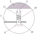
FIG. 1 is a schematic view of an irrigation system of an ecological and environmental-friendly agricultural greenhouse according to the present invention;
FIG. 2 is an enlarged view of the structure at the position A of the irrigation system of the ecological and environment-friendly agricultural greenhouse provided by the invention;
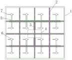
FIG. 3 is a sectional view taken along line B-B of FIG. 1;
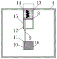
FIG. 4 is a schematic structural view of a water supply mechanism of an irrigation system of an ecological and environment-friendly agricultural greenhouse according to the present invention;
FIG. 5 is a cross-sectional view taken along line C-C of FIG. 4;
FIG. 6 is an assembly view of the baffle and the turntable of the irrigation system of the ecological and environmental-friendly green house according to the present invention;
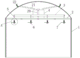
FIG. 7 is a schematic structural view of an irrigation system of an eco-friendly agricultural greenhouse according to embodiment 2 of the present invention;
fig. 8 is a side view of an irrigation system of an eco-friendly agricultural greenhouse according to embodiment 2 of the present invention.
In the figure: the greenhouse comprises a greenhouse body 1, a reticular steel reinforcement framework 2, a main pipe 3, a water storage tank 4, branch pipes 5, a shower head 6, fan blades 7, lifting plates 8, connecting rods 9, a rotary table 10, thin rods 11, fixing rods 12, expansion medium 13, a spring 14, a placing box 15, a baffle 16, a sleeve 17, a rotating blade 18, a spiral plate 19, an observation window 20, a water inlet pipe 21 and an arc plate 22.
Detailed Description
The technical solutions in the embodiments of the present invention will be clearly and completely described below with reference to the drawings in the embodiments of the present invention, and it is obvious that the described embodiments are only a part of the embodiments of the present invention, and not all of the embodiments.
Example 1
Referring to fig. 1-6, an ecological environment-friendly agricultural greenhouse irrigation system comprises a greenhouse body 1, wherein a reticular steel reinforcement framework 2 is arranged on the inner wall of the greenhouse body 1 close to the upper end, a water storage tank 4 is arranged at the upper end of the reticular steel reinforcement framework 2, the water storage tank 4 is positioned in the middle of the reticular steel reinforcement framework 2, the side wall of the water storage tank 4 is provided with an observation window 20, the observation window 20 is made of glass, the water level in the water storage tank 4 can be observed conveniently, the upper wall of the water storage tank 4 is provided with a water inlet, a worker can connect a water pipe at the water inlet, and extends downwards along the side wall of the shed body 1 to supply water to the water storage tank 4, water outlets are arranged on both side walls of the water storage tank 4, the upper and lower side walls of the water outlet are cambered surfaces, the water storage tank 4 is communicated with a header pipe 3 through the water outlet, the side wall of the header pipe 3 is communicated with a plurality of branch pipes 5, the branch pipes 5 are L-shaped, and the vertical portion of the branch pipe 5 is a hose made of rubber and the lateral portion of the branch pipe 5 is a water pipe made of plastic.
The lower extreme of a plurality of branch pipes 5 all is equipped with water spray mechanism, water spray mechanism includes sleeve pipe 17, the sleeve pipe 17 inner wall passes through the bearing and is connected with 5 lateral walls of branch pipe rotation, the outer lane and the sleeve pipe 17 inner wall fixed connection of bearing, inner circle and the outer wall fixed connection of branch pipe 5, the sleeve pipe 17 inner wall is equipped with spiral plate 19, it is decurrent to make water be the heliciform, sleeve pipe 17 inner wall fixed connection has rotating vane 18, and rotating vane 18 is located the 19 lower extremes of spiral plate, sleeve pipe 17 lateral wall symmetry is equipped with the flabellum 7 that two length are different, the intercommunication of sleeve pipe 17 lower extreme is equipped with gondola water faucet 6.
Two water supply mechanisms are arranged inside the water storage tank 4, each water supply mechanism comprises a placing box 15 which is arranged on the water storage tank 4 and close to the inner wall of the upper end, a lifting plate 8 is arranged on the inner wall of the placing box 15, the upper wall of the lifting plate 8 is elastically connected with the upper wall of the placing box 15 through a spring 14, the space of the placing box 15 above the lifting plate 8 is filled with expansion and contraction media 13, such as kerosene and the like, the lower wall of the lifting plate 8 is fixedly connected with a fixed rod 12, the fixed rod 12 penetrates through the lower wall of the placing box 15, a sealing ring is arranged at the penetrating position to prevent water in the water storage tank 4 from entering the placing box 15, the side wall of the water outlet is connected with a rotary table 10 through the rotation of the rotary table, the rotary table 10 fixedly penetrates through the side walls of the rotary table 10 and a baffle 16, the rotary table is rotatably inserted into the two side walls of the water outlet, the side walls of the rotary table 10 are fixedly connected with the baffle 16, the upper side wall and the lower side wall of the baffle 16 are cambered surfaces, the baffle 16 can be convenient to rotate at the water outlet, the side wall of the rotary table 10 close to the edge, a thin rod 11, and the thin rod 11 is positioned in the water storage tank 4, the fixed rod 12 is rotatably connected with the thin rod 11 through the connecting rod 9, and two ends of the connecting rod 9 are rotatably connected with the fixed rod 12 and the thin rod 11 through rotating shafts respectively.
In the invention, under normal temperature, the expansion and contraction medium 13 can not expand, the lifting plate 8 is positioned in the middle of the placing box 15 under the pulling force of the spring 14, at this time, the thin rod 11 is positioned at the upper part of the rotating disc 10, the baffle 16 is in a vertical state, water can not flow out of the water storage tank 4, when the temperature rises, the expansion and contraction medium 13 expands under heat, thereby extruding the lifting plate 8 downwards, the lifting plate 8 drives the fixing rod 12 to move downwards, the fixing rod 12 drives the rotating disc 10 to rotate towards the direction in the water storage tank 4 through the connecting rod 9, thereby driving the baffle 16 to rotate, water can flow out of the water storage tank 4, the higher the temperature is, the larger the expansion degree of the expansion and contraction medium 13 is, the larger the moving distance of the lifting plate 8 is, when the lifting plate 8 moves to the lowest end, the baffle 16 is just in a horizontal state, the water flows out faster until the temperature is reduced, and the expansion and contraction medium 13 recovers the original state, the lifting plate 8 is pulled by the spring 14 to return to the middle of the placing box 15, the baffle plate 16 is rotated to the vertical state, and the water supply is stopped.
Water flows to behind the 5 lower extremes of branch pipe from house steward 3, can get into sleeve pipe 17, receive the effect of spiral plate 19, water can be the heliciform and flow down, and drive the rotation leaf 18 and rotate, thereby it rotates to drive sleeve pipe 17, the flabellum 7 of sleeve pipe 17 lateral wall also rotates thereupon, because the length of two flabellums 7 is different, the centrifugal force that receives is also different, make sleeve pipe 17 can freely swing, water in the sleeve pipe 17 sprays crops through gondola water faucet 6 on, water for crops, when having not rivers in the sleeve pipe 17, sleeve pipe 17 stops the swing gradually.
Example 2
Referring to fig. 2-8, different from embodiment 1, the outer wall of the canopy body 1 of this embodiment near the top is provided with two arc-shaped plates 22, two sides of each arc-shaped plate 22 are high and the middle is low, the two sides of the canopy body 1 located at the lower side walls of the arc-shaped plates 22 are both communicated with a water inlet pipe 21, and one end of the water inlet pipe 21 far away from the arc-shaped plates 22 is communicated with the upper wall of the water storage tank 4.
Compare with embodiment 1, this embodiment can collect the rainwater at the rainy day, and the rainwater flows the lower position of arc 22 along the top of the canopy body 1, and the rethread inlet tube 21 can be to rainwater make full use of, has practiced thrift the water resource in flowing into storage water tank 4.
The above description is only for the preferred embodiment of the present invention, but the scope of the present invention is not limited thereto, and any person skilled in the art should be considered to be within the technical scope of the present invention, and the technical solutions and the inventive concepts thereof according to the present invention should be equivalent or changed within the scope of the present invention.
Claims (1)
1. The utility model provides an ecological environmental protection green house irrigation system, includes the canopy body (1), its characterized in that: the greenhouse is characterized in that a reticular steel bar framework (2) is arranged on the inner wall of the greenhouse body (1) close to the upper end, a water storage tank (4) is arranged on the upper end of the reticular steel bar framework (2), the water storage tank (4) is positioned in the middle of the reticular steel bar framework (2), an observation window (20) is arranged on the side wall of the water storage tank (4), both side walls of the water storage tank (4) are provided with water outlets, the upper side wall and the lower side wall of each water outlet are arc surfaces, the water storage tank (4) is provided with a header pipe (3) through the water outlets, the side wall of the header pipe (3) is provided with a plurality of branch pipes (5), the vertical parts of the branch pipes (5) are hoses made of rubber, the lower ends of the plurality of the branch pipes (5) are provided with water spraying mechanisms, two water supply mechanisms are arranged inside the water storage tank (4), each water supply mechanism comprises a placing box (15) close to the inner wall of the upper end of the water storage tank (4), and a lifting plate (8) is arranged on the inner wall of the placing box (15), the water storage tank is characterized in that the upper wall of the lifting plate (8) is elastically connected with the upper wall of the placing box (15) through a spring (14), the space, located above the lifting plate (8), of the placing box (15) is filled with a thermal expansion and cold contraction medium (13), the lower wall of the lifting plate (8) is fixedly connected with a fixing rod (12), the fixing rod (12) penetrates through the lower wall of the placing box (15), the side wall of the water outlet is rotatably connected with a rotary table (10) through a rotary rod, the side wall of the rotary table (10) is fixedly connected with a baffle (16), the upper side wall and the lower side wall of the baffle (16) are cambered surfaces, a thin rod (11) is arranged on the side wall, close to the edge, of the rotary table (10), the thin rod (11) is located in the water storage tank (4), and the fixing rod (12) is rotatably connected with the thin rod (11) through a connecting rod (9);
the water spraying mechanism comprises a sleeve (17), the inner wall of the sleeve (17) is rotatably connected with the side wall of the branch pipe (5) through a bearing, a spiral plate (19) is arranged on the inner wall of the sleeve (17), a rotating blade (18) is fixedly connected to the inner wall of the sleeve (17), the rotating blade (18) is positioned at the lower end of the spiral plate (19), two fan blades (7) with different lengths are symmetrically arranged on the outer side wall of the sleeve (17), and a shower head (6) is communicated with the lower end of the sleeve (17);
the rotating rod fixedly penetrates through the side walls of the turntable (10) and the baffle (16), and the rotating rod is rotatably inserted into the two side walls of the water outlet;
two ends of the connecting rod (9) are respectively and rotatably connected with the fixed rod (12) and the thin rod (11) through rotating shafts;
during the use, under normal temperature, expend with heat and contract with cold medium (13) can not expand, lifter plate (8) receive the pulling force of spring (14) to be located places box (15) middle part, this moment, slender pole (11) are located carousel (10) upper portion, baffle (16) are vertical state, water can not flow out from storage water tank (4), when the temperature risees, expend with heat and contract with cold medium (13) is heated and expanded, thereby extrude lifter plate (8) downwards, lifter plate (8) drive dead lever (12) move down, dead lever (12) drive carousel (10) through connecting rod (9) and rotate to the direction in storage water tank (4), thereby drive baffle (16) and rotate, hydroenergy flows out from storage water tank (4), the higher the temperature, expend with heat and contract with cold medium (13) the expanded degree is big, the larger the moving distance of the lifting plate (8), when the lifting plate (8) moves to the lowest end, the baffle (16) is just in a horizontal state, the faster the water flows out, until the temperature is reduced, and when the thermal expansion and cold contraction medium (13) is restored to the original state, the lifting plate (8) returns to the middle part of the placing box (15) under the tension of the spring (14), and the baffle (16) rotates back to a vertical state to stop supplying water;
water flows to branch pipe (5) lower extreme from house steward (3) after, can get into sleeve pipe (17), receive the effect of spiral plate (19), water can be the heliciform and flow down, and drive rotating vane (18) and rotate, thereby drive sleeve pipe (17) and rotate, flabellum (7) of sleeve pipe (17) lateral wall also rotate along with it, because the length of two flabellums (7) is different, the centrifugal force that receives is also different, make sleeve pipe (17) can freely swing, water in sleeve pipe (17) sprays crops through gondola water faucet (6) on, water for crops, when not having rivers in sleeve pipe (17), sleeve pipe (17) stop the swing gradually.
Priority Applications (1)
| Application Number | Priority Date | Filing Date | Title |
|---|---|---|---|
| CN201911071042.3A CN110692401B (en) | 2019-11-05 | 2019-11-05 | Ecological environmental protection green house irrigation system |
Applications Claiming Priority (1)
| Application Number | Priority Date | Filing Date | Title |
|---|---|---|---|
| CN201911071042.3A CN110692401B (en) | 2019-11-05 | 2019-11-05 | Ecological environmental protection green house irrigation system |
Publications (2)
| Publication Number | Publication Date |
|---|---|
| CN110692401A CN110692401A (en) | 2020-01-17 |
| CN110692401B true CN110692401B (en) | 2021-12-14 |
Family
ID=69204342
Family Applications (1)
| Application Number | Title | Priority Date | Filing Date |
|---|---|---|---|
| CN201911071042.3A Active CN110692401B (en) | 2019-11-05 | 2019-11-05 | Ecological environmental protection green house irrigation system |
Country Status (1)
| Country | Link |
|---|---|
| CN (1) | CN110692401B (en) |
Families Citing this family (1)
| Publication number | Priority date | Publication date | Assignee | Title |
|---|---|---|---|---|
| CN112790566B (en) * | 2020-12-30 | 2022-06-07 | 重庆水利电力职业技术学院 | Indoor design's artistic pergola |
Citations (12)
| Publication number | Priority date | Publication date | Assignee | Title |
|---|---|---|---|---|
| CN202262301U (en) * | 2011-09-21 | 2012-06-06 | 张意立 | Cylindrical tank using piston to regulate water discharge in proportion to sunlight intensity |
| CN102494181A (en) * | 2011-12-13 | 2012-06-13 | 北京林业大学 | Water-saving valve for irrigation |
| CN202890111U (en) * | 2012-09-27 | 2013-04-24 | 天津市誉农农作物种植专业合作社 | Water-saving pipe irrigation system |
| WO2015104852A1 (en) * | 2014-01-08 | 2015-07-16 | 株式会社テックコーポレーション | Thermosensitive valve and sprinkler system using same |
| CN204796385U (en) * | 2015-07-09 | 2015-11-25 | 杨旗 | A rotatory nozzle for multi -functional irrigation system |
| CN205102041U (en) * | 2015-11-02 | 2016-03-23 | 杭州富阳高博信息技术服务有限公司 | Landscape thermal louver of area sprinkling irrigation function |
| CN105532311A (en) * | 2016-02-04 | 2016-05-04 | 成都贝瑞生态农业开发有限公司 | Environment-friendly ecological agricultural greenhouse |
| CN106358840A (en) * | 2016-08-27 | 2017-02-01 | 滁州菲扬农业科技有限公司 | Agricultural greenhouse |
| CN206611880U (en) * | 2017-03-11 | 2017-11-07 | 王义溥 | A kind of environmentally friendly agricultural planting greenhouse |
| CN207383156U (en) * | 2017-10-30 | 2018-05-22 | 杨欢 | A kind of irrigation and water conservancy irrigation rig |
| CN207744457U (en) * | 2017-12-01 | 2018-08-21 | 魏志秋 | A kind of irrigation rig of gross area covering |
| CN109287443A (en) * | 2018-11-16 | 2019-02-01 | 郝诗敏 | A kind of park automatic water system |
Family Cites Families (1)
| Publication number | Priority date | Publication date | Assignee | Title |
|---|---|---|---|---|
| US10595474B2 (en) * | 2017-05-31 | 2020-03-24 | Insectergy, Llc | Cannabis farming systems and methods |
-
2019
- 2019-11-05 CN CN201911071042.3A patent/CN110692401B/en active Active
Patent Citations (12)
| Publication number | Priority date | Publication date | Assignee | Title |
|---|---|---|---|---|
| CN202262301U (en) * | 2011-09-21 | 2012-06-06 | 张意立 | Cylindrical tank using piston to regulate water discharge in proportion to sunlight intensity |
| CN102494181A (en) * | 2011-12-13 | 2012-06-13 | 北京林业大学 | Water-saving valve for irrigation |
| CN202890111U (en) * | 2012-09-27 | 2013-04-24 | 天津市誉农农作物种植专业合作社 | Water-saving pipe irrigation system |
| WO2015104852A1 (en) * | 2014-01-08 | 2015-07-16 | 株式会社テックコーポレーション | Thermosensitive valve and sprinkler system using same |
| CN204796385U (en) * | 2015-07-09 | 2015-11-25 | 杨旗 | A rotatory nozzle for multi -functional irrigation system |
| CN205102041U (en) * | 2015-11-02 | 2016-03-23 | 杭州富阳高博信息技术服务有限公司 | Landscape thermal louver of area sprinkling irrigation function |
| CN105532311A (en) * | 2016-02-04 | 2016-05-04 | 成都贝瑞生态农业开发有限公司 | Environment-friendly ecological agricultural greenhouse |
| CN106358840A (en) * | 2016-08-27 | 2017-02-01 | 滁州菲扬农业科技有限公司 | Agricultural greenhouse |
| CN206611880U (en) * | 2017-03-11 | 2017-11-07 | 王义溥 | A kind of environmentally friendly agricultural planting greenhouse |
| CN207383156U (en) * | 2017-10-30 | 2018-05-22 | 杨欢 | A kind of irrigation and water conservancy irrigation rig |
| CN207744457U (en) * | 2017-12-01 | 2018-08-21 | 魏志秋 | A kind of irrigation rig of gross area covering |
| CN109287443A (en) * | 2018-11-16 | 2019-02-01 | 郝诗敏 | A kind of park automatic water system |
Also Published As
| Publication number | Publication date |
|---|---|
| CN110692401A (en) | 2020-01-17 |
Similar Documents
| Publication | Publication Date | Title |
|---|---|---|
| CN204482816U (en) | A kind of landscape sprinkler device | |
| CN107567884B (en) | Automatic sprinkling irrigation cultivation greenhouse | |
| CN109042263B (en) | Gardens of driping irrigation are cultivated and are used device of driping irrigation according to potted landscape gravity open | |
| CN110692401B (en) | Ecological environmental protection green house irrigation system | |
| CN110604038B (en) | Ecological slope protection greening water supply system | |
| CN207519326U (en) | A kind of greenhouse water-saving irrigation nozzle | |
| CN112544396A (en) | Sponge urban road green space system of greenbelt | |
| CN205902521U (en) | Greenhouse irrigation system | |
| CN213204723U (en) | Green roof of commercial complex | |
| CN211129275U (en) | Drip irrigation zone monitoring device | |
| CN202697367U (en) | Solar collection type roof sunlight greenhouse | |
| CN220768635U (en) | Green building energy-saving roof for building construction | |
| CN111406617A (en) | Gardens irrigation equipment convenient to water conservation | |
| CN213368960U (en) | Sunshade with irrigation cooling function | |
| CN116575628B (en) | Green building roof structure | |
| CN212876923U (en) | Solar greenhouse with heating function | |
| CN203684325U (en) | Fully-automatic cleaning type efficient external-force-free water storage tank | |
| CN217680079U (en) | Roof structure of green energy-saving building | |
| CN114145215B (en) | Rainwater collection and irrigation device capable of preventing water from freezing for municipal road greening | |
| CN220255196U (en) | Multifunctional flower bed | |
| CN210202664U (en) | Winter greenhouse | |
| CN214784751U (en) | Steel structure supporting structure of green building | |
| CN214229263U (en) | Agricultural intelligent water-saving facility | |
| CN217038254U (en) | Agricultural economy water conservation sprinkling irrigation system | |
| CN214430799U (en) | Water-saving irrigation device for rice planting |
Legal Events
| Date | Code | Title | Description |
|---|---|---|---|
| PB01 | Publication | ||
| PB01 | Publication | ||
| SE01 | Entry into force of request for substantive examination | ||
| SE01 | Entry into force of request for substantive examination | ||
| TA01 | Transfer of patent application right |
Effective date of registration: 20211125 Address after: No.2, F-type factory building, No.18, Yunlong Road, Longhu high tech Zone, Huaibei Economic Development Zone, Anhui Province Applicant after: Huaibei hehuoren Technology Co.,Ltd. Address before: 201306 No. 833 Huangsha, Xingwang village, Nicheng Town, Pudong New Area, Shanghai Applicant before: Lin Jinguo |
|
| TA01 | Transfer of patent application right | ||
| GR01 | Patent grant | ||
| GR01 | Patent grant |